
May, 1999
General Information
This technical service bulletin discusses the set-up of thermocompression bonding equipment to be used with 3M Z-Axis Bonding Film in the interconnection of flexible circuits to printed circuit boards (PCB), ITO/glass LCD circuits or other flexible circuits. This document should be used in conjunction with the Bonding Sequence Technical Bulletin and the Data Page for the particular 3M Z-Axis Bonding Film product of interest.
Summary
Obtaining consistent, low resistance electrical interconnections with 3M Z-Axis Bonding Films requires optimization of the bonding technique. Specific bonding profiles for each particular 3M film product may be found in their respective data pages. Proper set-up of the thermocompression bonder also plays a pivotal role:
- Choice of thermocompression bonder type
- Flatness of the bonding thermode
- Applying the proper force and temperature profile to the bond line
- Use of appropriate conformal silicone rubber materials
Choice of Thermocompression Bonder Type
There are two general categories of bonders: constant-temperature thermode bonders (hot bar) and processor-controlled bonders (pulsed heated). It is important to understand the differences between the bonder types, as their characteristics affect the exact bonding conditions.
The constant-temperature bonder has its thermode held at a constant temperature (usually set above the adhesive cure temperature in the bond line temperature). Upon application of the thermode to the assembly to be bonded, the temperature profile in the bond line takes on the appearance shown in Figure 1. During the cure cycle the temperature rises and this may be important when bonding temperature sensitive flexible substrates such as PET/silver ink flexible circuits. Constant-temperature hot bar bonders are relatively inexpensive.
A processor-controlled bonder can apply power to the thermode in the form of electric current pulses to rapidly increase the bar temperature. Upon application of the thermode to the assembly to be bonded, the temperature profile in the bond line takes on the appearance shown in Figure 2. The pulse bonder can be programmed to rapidly reach the desired bonding temperature and hold the temperature at the desired level. Temperature sensitive substrates can easily be protected against overheating. Processor-controlled bonders are typically more expensive than constant-heat bonders.
Thermode Alignment
The thermode must be flat and square with the stage and the parts to be assembled in order to apply uniform pressure on the bond line. Alignment can be verified by checking the uniformity of pressure between the thermode and the bonder stage and assembly using prescale film. Prescale film turns colors under pressure (darker color = higher pressure).
With the thermode at room temperature the prescale film is placed below the thermode onto the bonding stage and the thermode is brought down. The imprint of the thermode onto the film should be visible and unifom1 in color. Any nonuniformity indicates adjustment of the thermode is required (see Figure 3). After making any adjustments angle or flatness this verification step must be repeated.
Once thermode flatness and alignment with the bonding stage has been assured, the pressure uniformity of the thermode onto the assembly to be bonded may be checked. Using a dummy layup of the assembly (with no 3M Z-Axis Adhesive Film present) put prescale film on top of the flex circuit. Rather than a uniform imprint of the the1mode as was seen above, you should see the imprint of the underlaying circuit lines. All visible circuit trace imprints should be of the same color intensity (the same pressure). If non-uniform images of the circuit lines are seen the assembly and thermode are not aligned properly and the user should adjust the fixturing of the assembly or re-adjust the thermode. Repeat this procedure until the circuit lines show uniformity in pressure. The imprint will also reveal the con-ect value for contact area of the thermode on the assembly for use in force determination (see section below).
Use of Compliant Layer
Superior bond results (consistent, low resistance) may be obtained when a compliant layer is used between the thennode and the top of the assembly to be bonded. Thermally conductive silicone rubber is the recommended materialC2′. The compliant layer serves to even out the pressure and applied heat to the individual circuit lines. Compliant silicone rubber may become brittle after several bonding cycles, particularly when mounted into a T slot thermode, and should be replaced periodically
Note: Using a compliant sheet of excessive thickness may result in excessive adhesive flow and an increased risk of short circuits between circuit lines. Compliant layer thickness recommendations are provided in the Bonding Sequence Technical Bulletin for the particular 3M ZAF product.
Force Determination
To properly set the force on the thermode the contact area between the thermode and the flex circuit must be determined. The length of Z-Axis Adhesive Film to use should be at least as long as the width of the flex circuit to be bonded. Once the area of the bond line is determined, the force to apply to the bond line is determined by:
Desired force = desired pressure x contact area
The desired pressure will be given in the Data Sheet for the specific 3M Z-Axis Adhesive Film product under consideration. The contact area is best determined using an imprint on the prescale film as described at the end of the “Thermode Alignment” section above.
Once the desired force is known, the instrument pressure setting must be determined. With most bonders the instrument pressure gauge reading is not the actual force applied, but rather the air pressure pushing on a cylinder which transfers the force to the thermode. To determine the proper pressure setting:
Instrument pressure setting = desired force / bonder cylinder bore area
The bonder manufacturer should provide the bonder cylinder bore area and/or a conversion factor between the gauge reading and the delivered force. Be aware that in some cases this conversion factor assumes the entire area of the thermode has been applied to the bond line, which is not the case when the thermode is wider than the flex circuit.
Temperature Set-Up
To determine the proper thermode setting (constant-temperature bonder) or programmed profile (processor-controlled bonder) the user must perform a series of trial bonds to measure the actual temperature in the bond line of the assembly. The thermode temperature will necessarily have to be set to a higher setpoint than the desired temperature in order to compensate for the thermal resistance of the flex circuit and compliant layer, plus the heat losses into the other parts of the assembly and the bonder stage.
Measurement of the bond line temperature is achieved by placing a thin thermocouple<3l in a dummy assembly of the flex circuit and the other substrate (without the presence of the 3M Z-Axis Bonding Film, but including the compliant layer), see Figure 4. Whenever possible the thermocouple should be placed between any circuit lines (in particular with PET/silver ink flex circuit bonding) to prevent erroneous reading of the temperature. The thermocouple must be connected to a digital thermometer with a sufficiently rapid response time to detect the rapid temperature rise during the first few seconds of the bonding cycle.
Check the specific Data Page of the 3M Z-Axis Adhesive Film to obtain the desired heat rise time, final bond line temperature and total bonding cycle time. The user then must make adjustments to the thermode temperature or programmed profile to achieve the desired bonding cycle. This process of temperature cycle optimization must be repeated for each new assembly to be bonded as thermal chai·acteristics and therefore bond line temperatures may change even with minor alterations in the assembly (e.g. the circuit pattern).
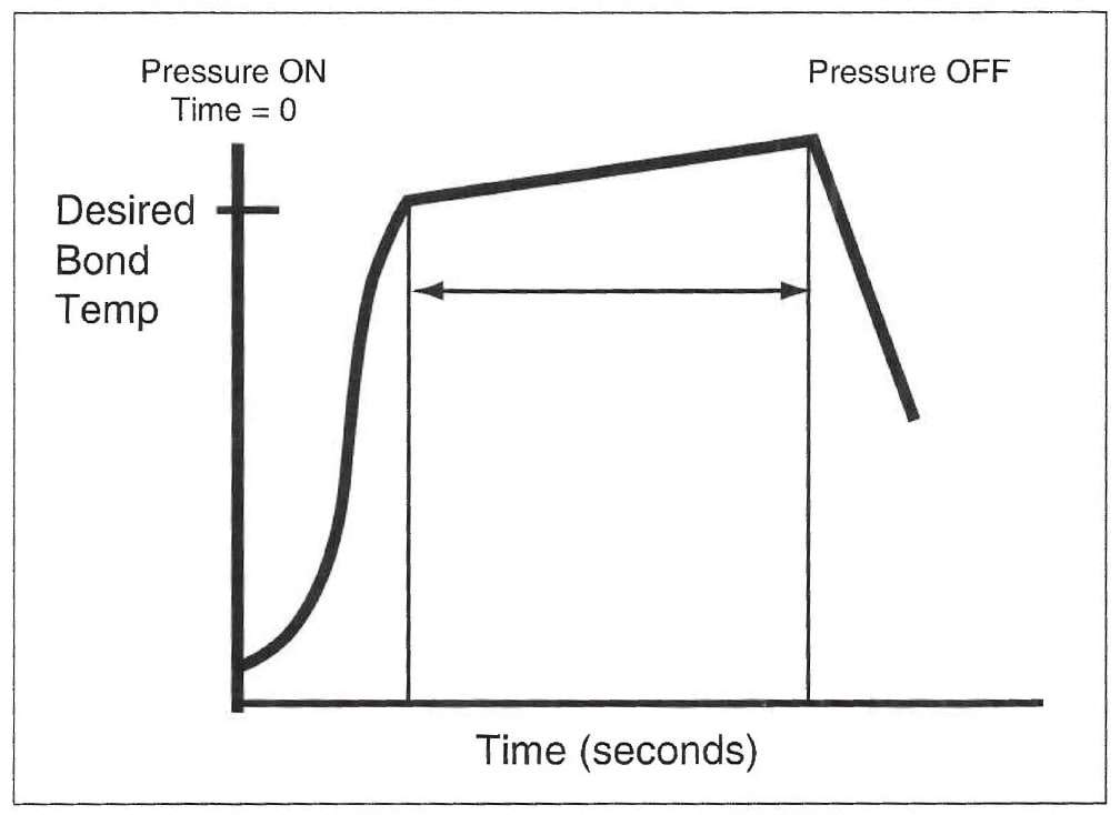
Figure 1. Idealized bond line temperature profile from a constant-temperature bonder. Notice the “overshoot” of the desired temperature inherent in this type of bonder.
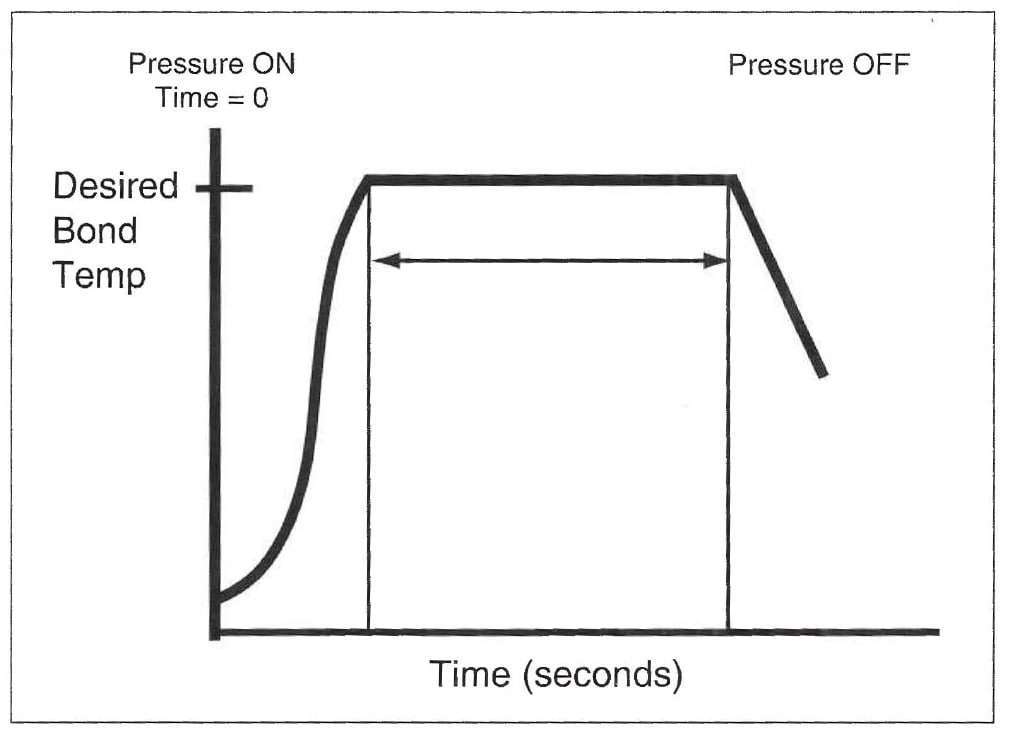
Figure 2. Idealized bond line temperature profile from a processor-controlled bonder. Notice the more constant temperature control during the bond cycle that is possible with this type of bonder.
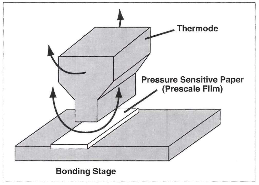
Figure 3. Lay-Up of Thermode and prescale film to measure pressure uniformity. Arrow represent axes through which the thermode alignment can be adjusted to generate uniform pressure over the bond line.
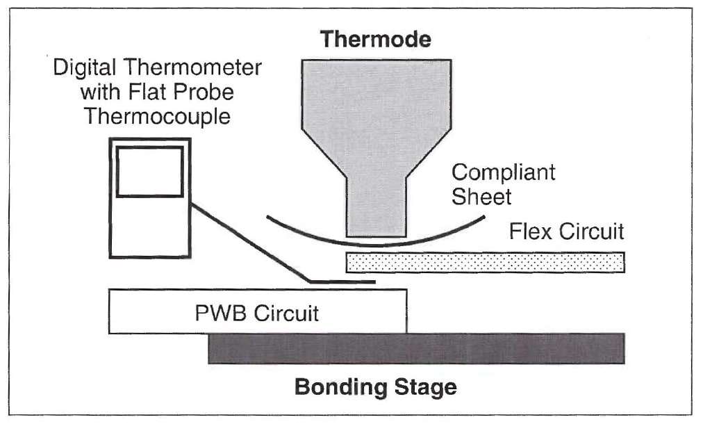
Figure 4. Lay-Up of dummy circuits to determine the Thermode temperature setting.
For Additional Information
To request additional product information or to arrange for sales assistance, call toll free 1-800-362-3550. Address correspondence to: 3M Bonding Systems Division, 3M Center, Building 220-7E-01, St. Paul, MN 55144-1000. Our fax number is 651-733-9175. In Canada, phone: 1-800-364-3577. In Puerto Rico, phone: 1-809-750-3000. In Mexico, phone: 5-728-2180.
Important Notice
3M MAKES NO WARRANTIES, EXPRESS OR IMPLIED, INCLUDING, BUT NOT LIMITED TO, ANY IMPLIED WARRANTY OF MERCHANTABILITY OR FITNESS FOR A PARTICULAR PURPOSE. User is responsible for determining whether the 3M product is fit for a particular purpose and suitable for user’s method of application. Please remember that many factors can affect the use and performance of a 3M product in a particular application. The materials to be bonded with the product, the surface preparation of those materials, the product selected for use, the conditions in which the product is used, and the time and environmental conditions in which the product is expected to perform are among the many factors that can affect the use and performance of a 3M product. Given the variety of factors that can affect the use and performance of a 3M product, some of which are uniquely within the user’s knowledge and control, it is essential that the user evaluate the 3M product to determine whether it is fit for a particular purpose and suitable for the user’s method of application.
Limitation of Remedies and Liability
If the 3M product is proved to be defective, THE EXCLUSIVE REMEDY, AT 3M’S OPTION, SHALL BE TO REFUND THE PURCHASE PRICE OF OR TO REPAIR OR REPLACE THE DEFECTIVE 3M PRODUCT. 3M shall not otherwise be liable for loss or damages, whether direct, indirect, special, incidental, or consequential, regardless of the legal theory asserted, including negligence, warranty, or strict liability.