

Article
Related Links
Sung-Jae Kim, Yong-Min Chun, Sung-Hwan Kim, Hong-Kyo Moon, and Jae-Won Jang
Department of Orthopaedic Surgery, Arthroscopy and Joint Research Institute, Yonsei University College of Medicine, Seoul, Korea.
Purpose
The purpose of this study was to compare four graft-tunnel angles (GTA), the femoral GTA formed by three different femoral tunneling techniques (the outside-in, a modified inside-out technique in the posterior sag position with knee hyperflexion, and the conventional inside-out technique) and the tibia GTA in 3-dimensional (3D) knee flexion models, as well as to examine the influence of femoral tunneling techniques on the contact pressure between the intra-articular aperture of the femoral tunnel and the graft. Materials and Methods: Twelve cadaveric knees were tested. Computed tomography scans were performed at different knee flexion angles (0°, 45°, 90°, and 120°). Femoral and tibial GTAs were measured at different knee flexion angles on the 3D knee models. Using pressure sensitive films, stress on the graft of the angulation of the femoral tunnel aperture was measured in posterior cruciate ligament reconstructed cadaveric knees. Results: Between 45° and 120° of knee flexion, there were no significant differences between the outside-in and modified inside-out techniques. However, the femoral GTA for the conventional inside-out technique was significantly less than that for the other two techniques (p < 0.001). In cadaveric experiments using pressure-sensitive film, the maximum contact pressure for the modified inside-out and outside-in technique was significantly lower than that for the conventional inside-out technique (p=0.024 and p=0.017). Conclusion: The conventional inside-out technique results in a significantly lesser GTA and higher stress at the intra-articular aperture of the femoral tunnel than the outside-in technique. However, the results for the modified inside-out technique are similar to those for the outside-in technique.
Keywords: Posterior cruciate ligament, reconstruction, graft-tunnel angle, 3-dimensional
Introduction
The clinical outcomes of posterior cruciate ligament (PCL) reconstruction are less satisfactory and less predictable than those of anterior cruciate ligament (ACL) reconstruction.1,2 A variety of surgical techniques and graft materials have been used for PCL reconstruction,1 but the procedure remains challenging. Several authors have reported that the grafted substances can become stretched due to the concentration of stress caused by the acute angle between the graft and the intra-articular apertures of the tunnels.2-7 In arthroscopic PCL reconstruction, femoral tunnels can be created with either the outside-in (two-incision) or inside-out (one-incision) techniques. The inside-out technique makes the femoral socket through the anterolateral portal.8,9 Although the inside-out technique minimizes potential injury to the vastus medialis obliquus, several researchers have suggested that it sharpens the femoral graft-tunnel angle formed between the graft and the intra-articular aperture of the femoral tunnel, causing increased attritional stress.5-7 However, most studies for the femoral graft-tunnel angle have been performed in the context of two dimensions rather than three dimensions, and no studies have determined whether the results vary in relation to the flexion angle of the knee. In addition, consideration has rarely been given in regards to modification of the conventional inside-out technique.10,11 During formation of the femoral tunnel with the inside-out technique, hyperflexion of the knee increased the femoral graft tunnel angle in the sagittal plane, and pushing back the proximal tibia back while creating the femoral tunnel through the far anterolateral portal increased the femoral graft tunnel angle in the axial plane.7,10,11
Therefore, the objectives of this study were two-fold: 1) To compare the four different graft-tunnel angles, the femoral graft-tunnel angle formed by the three different femoral tunnel techniques (the outside-in; the modified inside-out, the inside-out technique in posterior sag position with knee hyperflexion; and the conventional inside-out technique) and the tibia graft-tunnel angle, as measured on three-dimensional (3D) knee flexion model; and 2) to examine the influence of different femoral tunneling techniques on the contact pressure between the intra-articular aperture of the femoral tunnel and the graft. We hypothesized that the modified inside-out technique would create less of an acute femoral graft-tunnel angle and lower stress at the intra-articular aperture of the femoral tunnel compared to the conventional inside-out technique and that the above values would be similar to the outside-in technique.
Materials and Methods
Three-dimensional angle measurement
This study was approved by our institutional review board. A prospective power analysis was performed using power calculation tool for paired t-test in PASS software (version 2008, NCSS statistical software, Kaysville, UT, USA). Based on previous literature,4,6,7 means of difference and standard deviations (SDs) of difference in graft-tunnel angle were defined as 17.9° and 16.7°, respectively. A sample size analysis with a power of 80% and an alpha of 0.008 (after adjustment for six pair-wise comparison using Bonferroni method) showed that 12 subjects were required.
Twelve fresh frozen cadaveric knees (age range, 45-77) were used; they had no evidence of previous surgery or deformity. Examination with anteroposterior and lateral plain X-rays as well as clinical examination revealed no pathologic findings. Each specimen was thawed for 24 hours at room temperature before imaging and testing. The femurs and tibias were cut approximately 25 cm from the joint line. First, in order to construct the 3D knee flexion models, each specimen was scanned with a slice interval of 0.625 mm using a 16-channel CT scanner (GE Healthcare, Buckinghamshire, UK) at four different knee flexion angles: 0°, 45°, 90° and 120°. Digital Imaging and Communications in Medicine files were segmented into 3D volumetric models. Registration of the 3D images of the tibia at each flexion angle allowed us to develop the 3D knee flexion models for each specimen (Fig. 1). During the registration of the 3D images, the mean 3D least square fitting tolerance was recorded at 0.075 mm. All processing and measurements were performed with validated software (Mimics® 14.0, Materialise, Leuven, Belgium).12,13
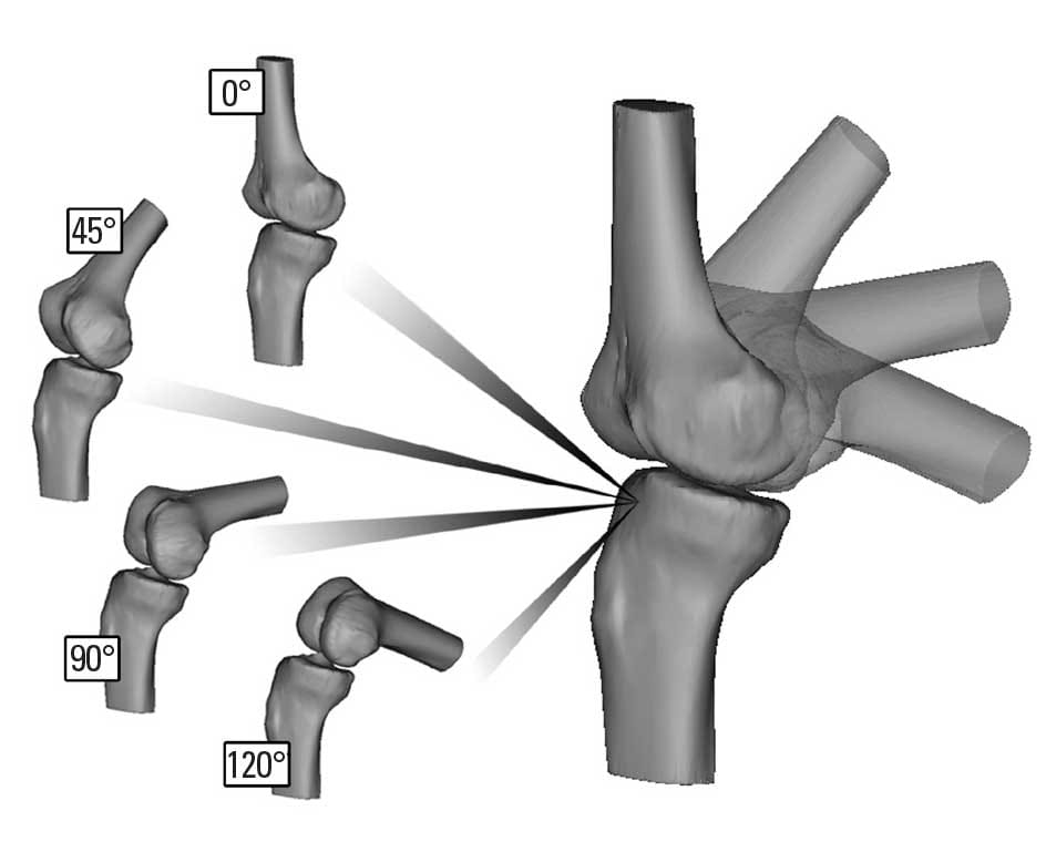
Fig. 1. To construct 3-dimensional (3D) k
nee flexion models, the 3D images of the tibia at four different knee flexion angles (0°, 45°, 90°, and 120°) were registered for each specimen.
Then, the femoral portion of the PCL was arthroscopically debrided and the femoral footprint of the PCL was identified. We passed three different guide pins though the center of the anatomic footprint of the anterolateral bundle of the PCL, 7 to 8 mm posterior from the edge of the articular cartilage, at the 1:30 o’clock position for the right knee and the 10:30 o’clock position for the left knee.14
The first femoral guide pin was placed with the outside-in technique. The arm of the guide (Acufex, Smith & Nephew, Andover, MA, USA) was introduced into the knee through the high medial parapatellar portal and a stab incision on the medial thigh allowed insertion of the guide pin sleeve to the bone. We then passed the guide pin, beginning at a point halfway between the medial femoral epicondyle and the trochlear articular margin of the medial femoral condyle, until it reached the center of the PCL anterolateral bundle footprint. The guide pin was withdrawn until the intra-articular end was no longer visible. The second femoral guide pin was placed with the conventional inside-out technique, which involved the use of the standard anterolateral portal and the knee in 90° of flexion. The pin was advanced freehand through the anterolateral portal, which was located approximately 10 mm above the lateral joint line and 10 mm lateral to the margin of the patellar tendon to the center of the anterolateral bundle footprint of the PCL, emerging outside of the medial femoral condyle. The third femoral guide pin was placed with the modified inside-out technique which involved the use of the far anterolateral portal with the knee in 110° of flexion and the proximal tibia pushed backwards. The guide pin was introduced through the far anterolateral portal, which was located just above the joint line and 5 mm anterior to the lateral femoral condyle toward the center of the anterolateral bundle footprint of the PCL. With the knee in 110° of flexion and the posterior translation of the proximal tibia maintained, the guide pin was advanced through the femoral tunnel site.10,11
To indicate the intra-articular site of the tibial tunnel with the anterolateral transtibial technique, the PCL was resected through a posterior capsular incision. The tibial guide tip (Acufex, Smith & Nephew, Andover, MA, USA) was placed about 1 cm below the articular surface and just lateral to the midline on the PCL fossa.2,15 The tibial guide pin was passed through the starting point of the tibial tunnel at 2 cm posterolateral from the anterior tibial tuberosity and about 4 cm below the joint line. To standardize the technique, the same surgeon placed all guide pins.4
After removing all guide pins, we scanned each specimen with a CT scanner at 0° extension following the same procedure described above. The reconstructed femoral and tibial images, which had intra-articular and outer cortical apertures made by guide pins, were separately registered into the previously obtained knee flexion model (Fig. 2). Using this method enabled us to identify the centers of the intra- and extra-articular apertures of the femoral tunnels made by three different techniques and the tibial tunnel that were made during surgery in each specimen; these were not virtual points created in the 3D flexion model.
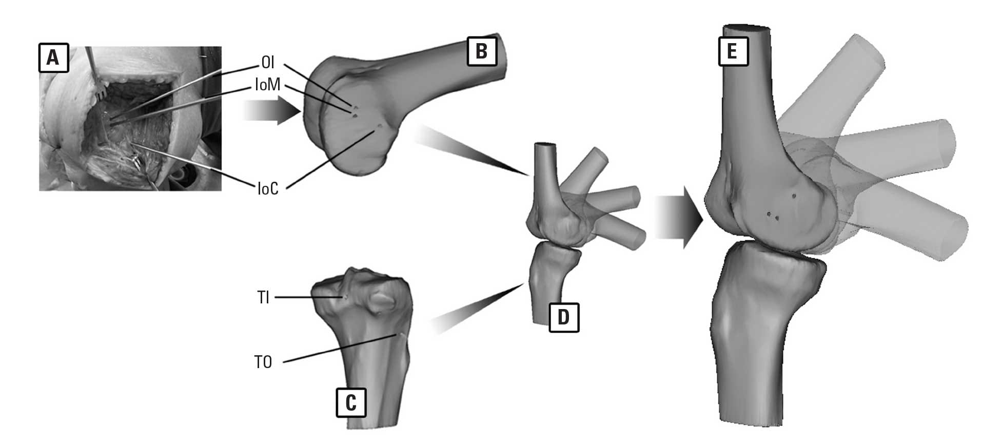
Fig. 2. (A) Three different guide pins (OI, the outside-in technique; IoM, the modified inside-out technique; IoC, the conventional inside-out technique) were passed through the center of the anterolateral bundle of the PCL. After removing all guide pins, each specimen was scanned and reconstructed. The reconstructed femoral (B) and tibial (C) images, which had intra-articular and outer cortical apertures made by guide pins (TI, intra-articular aperture of the anterolateral tibial tunnel; TO, outer cortical aperture of the anterolateral tibial tunnel), were separately registered into the previously obtained knee flexion model (D). (E) This method enabled us to make a 3D flexion model with constant apertures of the femoral and tibial tunnels that were made during surgery. PCL, posterior cruciate ligament; 3D, 3-dimensional.
In 3D space, two lines have a point in common must be coplanar. The angle formed by two intersecting lines in 3D space can be measured in a datum plan in which the two lines and intersecting point exist. To measure the femoral graft-tunnel angle the datum plane including the intra- and extra-articular apertures of the femoral tunnel and the intra-articular aperture of the tibial tunnel was chosen. The femoral graft-tunnel angle was measured for each technique on an individual datum plane (Fig. 3). The tibial graft-tunnel angle was measured similarly in a datum plane including the intra- and extra-articular apertures of the tibial tunnel and the intra-articular aperture of the femoral tunnel, which was the same for the three femoral tunneling techniques.
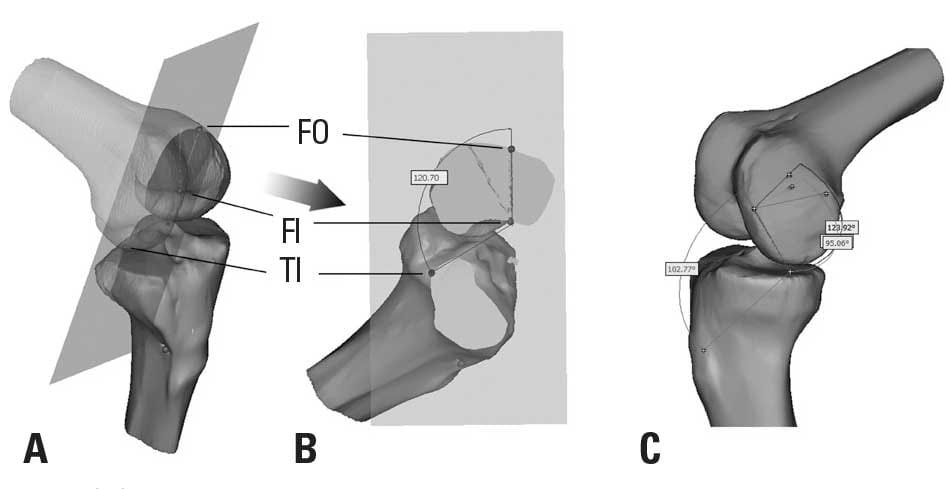
Fig. 3. (A) To measure the femoral graft-tunnel angle, the datum plane including the intra- and extra-articular apertures of the femoral tunnel (FI and FO, respectively) and the intra-articular aperture of the tibial tunnel (TI) was chosen. (B) The femoral graft-tunnel angle was measured for each technique on an individual datum plane. (C) Images show 3D-measurements of the femoral critical corner angle and the tibial killer turn angle from an anteromedial view. 3D, 3-dimensional.
Cadaveric experiments
Twelve fresh-frozen knees were tested after CT scanning. The specimens were allocated into one of three groups (n=4 per group) based on the femoral tunneling technique: 1) the outside-in technique, 2) the modified inside-out technique and 3) the conventional inside-out technique. Autogenous central bone-patellar tendon-bone grafts of 10 mm in width and 30 mm bone plugs were harvested and used as the graft material for all groups. A 10 mm diameter femoral tunnel and a 10 mm diameter tibial tunnel were made along the reinserted guide pin. After passing the graft, the femoral and tibial bone plugs were secured with 9×25 mm metal interference screws (Linvatec, Largo, FL, USA). For all groups, the tibial side of the graft was secured first. The bone plug was placed just inferior to the intra-articular aperture of the tibial tunnel. After that, the femoral side of the graft was tensioned to 89 N with the knee in 90° of flexion using a SETM Graft Tensioner (Linvatec, Largo, FL, USA). An anterior force of 156 N was applied to the proximal tibia, simulating an anterior drawer maneuver.2,16,17
To evaluate the magnitude of pressure occurring between the graft surface and the region around the intra-articular aperture of the femoral tunnel, we used Fuji Prescale pressure-sensitive film (Prescale LW, Fuji Film Co., Tokyo, Japan).4,18,19 The pressure range of the Prescale LW film varied from 2.5 to 10.0 MPa. The film was cut into 8×10 mm rectangles and covered on both sides with a thin clear wrap to waterproof the film.18 The film packet was then inserted between the graft and the intra-articular aperture of the femoral tunnel just before securing the femoral side of the graft. To reduce the unwished effect of the interferences screw and the bone plug, the femoral bone plug was placed with the patellar tendon positioned posteroproximally in anatomical position, while the screw was placed in the anterodistal aspect of the tunnel. In all cases the position of the femoral bone plug was at least 5 mm medial to the intra-articular aperture and the screw was inserted in an outside-in manner.
The femur and tibia were potted in epoxy compound and mounted in a custom testing jig, and the relative movement between the tibia and femur was simulated with MTS 858.20 (MTS system, Minneapolis, MN, USA) under 90° of knee flexion (Fig. 4). Then, a single test cycle was applied. A downward load of up to 150 N was applied to the femur and measured by the MTS load cell.2 After the experiment, the pressure-sensitive films were scanned into a desktop computer with an Epson V330 scanner (Seiko Epson Co., Nagano, Japan), and the average contact pressure and the maximal contact pressure were evaluated using FPD-8010E software (Fujifilm Pressure Distribution Mapping System for Prescale, Fuji Film Co., Tokyo, Japan). Ambient temperature and humidity were recorded and used in analysis, as recommended by the manufacturer.
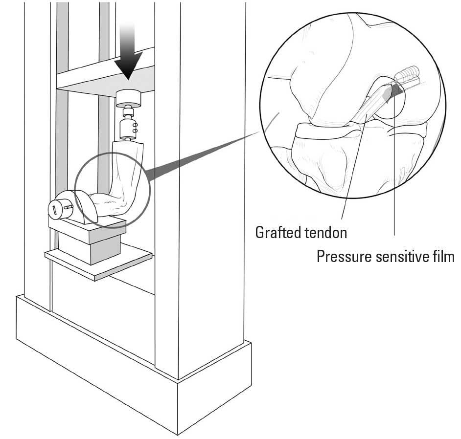
Fig. 4. Mounted on the specially designed jigs under 90° of knee flexion, the femur was forced to move downward (anterior direction) with a force of 150 N. The pressure sensitive thin film was inserted between the graft and the intra-articular aperture of the femoral tunnel.
Statistical analysis
For the 3D models, the data consisted of measurements of the three different femoral graft-tunnel angles and the tibial graft-tunnel angle at four different flexion angles on the same knee. This introduced a correlation structure between the observations obtained from the same knee. Thus, a linear mixed model was used for statistical analysis, and a Bonferroni approach was used to adjust the alpha level for pairwise post hoc comparisons. To assess intra- and inter-observer variability, two orthopaedic surgeons each performed all measurements twice with an interval of one week between measurements; the reliability of the measurements was evaluated with intraclass correlation coefficients (ICC). In cadaveric experiments with the pressure sensitive film, both the average and maximum contact pressures in each group were evaluated and analyzed with a Kruskal-Wallis test. Tukey test using rank was used for post hoc comparison. SPSS software (version 18.0; SPSS Inc., Chicago, IL, USA) was used for all analyses, and data presented as mean±SD for the graft-tunnel angle or median (range) for contact pressure measurements. p-values < 0.05 were considered statistically significant.
Results
Three-dimensional analyses
For all three femoral tunneling techniques, the femoral graft-tunnel angle tended to decrease as knee flexion increased between 0° and 120° (p < 0.001). Conversely, for all techniques, the tibial graft-tunnel angle was lowest at 45° of knee flexion. And it significantly increased as knee flexion increased between 45° and 120° (p < 0.001) (Fig. 5A).
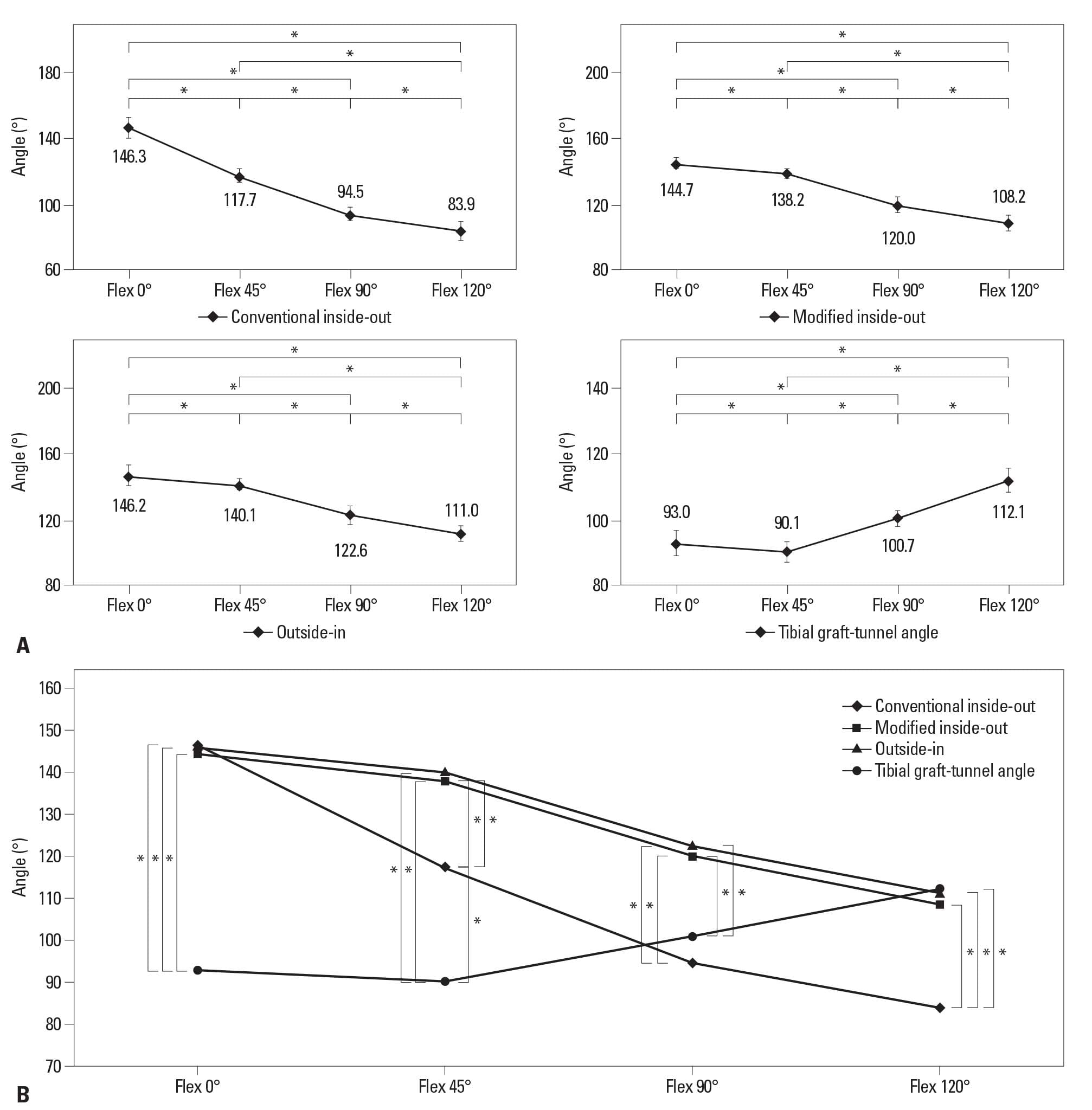
Fig. 5. Angles were measured for the 3D models at different knee flexion angles: 0°, 45°, 90°, and 120° (mean±standard deviation). (A) For all three femoral tunneling techniques, the femoral graft-tunnel angle tended to decrease as knee flexion increased (*p < 0.001). Conversely, the tibial graft-tunnel angle was lowest at 45° of knee flexion and it significantly increased as knee flexion increased between 45° and 120° (*p < 0.001). (B) Between 45° and 120° of knee flexion, the femoral graft-tunnel angle for the conventional inside-out technique was significantly more acute than that for the other two techniques (*p < 0.001). Also, the femoral graft-tunnel angle for the conventional inside-out technique was significantly more acute than the tibial killer turn angle at 120° of knee flexion (*p < 0.001). 3D, 3-dimensional.
The femoral graft-tunnel angles did not significantly differ between the three techniques at 0° of knee flexion. At 45° of knee flexion, the mean femoral graft-tunnel angle was 140.1±2.6° for the outside-in technique, 138.2±3.4° for the modified inside-out technique, and 117.7±3.6° for the conventional inside-out technique. These values were not significantly difference between the outside-in and modified inside-out techniques (p=0.554), but they were significant between the modified inside-out and conventional inside-out techniques (p < 0.001). Similar results were obtained for 90° of flexion (outside-in, 122.6±6.0°; modified inside-out, 120.0±5.5°; conventional inside-out, 94.5±3.5°) and 120° of flexion (outside-in, 111.0±4.1°; modified inside-out, 108.2±5.4°; conventional inside-out, 83.9±5.7°). In addition, the femoral graft-tunnel angles for the outside-in and modified inside-out techniques were significantly less acute than the tibial graft-tunnel angle between 0° and 90° of knee flexion (p < 0.001), but no significant difference was found at 120° of knee flexion. In contrast, the femoral graft-tunnel angle was significantly more acute than the tibial graft-tunnel angle at 120° of knee flexion for the conventional inside-out technique (p < 0.001) (Fig. 5B). The ICC values were 0.96 for intra-observer variability and 0.92 for inter-observer variability.
Cadaveric experiments (Fig. 6)
The three groups differed significantly in the average and maximum contact pressure (p=0.025 and p=0.022, respectively). The average contact pressure in the conventional inside-out group (4.425 MPa, range 4.20 to 4.60) was significantly higher than that of the outside-in group (3.325 MPa, range 3.05 to 3.55) (p=0.012) and the modified inside-out group (3.275 MPa, range 2.90 to 3.60) (p=0.012). However, the modified inside-out group and the outside-in group did not differ significantly (p=0.792). Likewise, in the maximum contact pressure, the values for the conventional inside-out group (12.325 MPa, range 9.60 to 12.75) were significantly higher than those for the modified inside-out group (6.125 MPa, range 5.10 to 7.30) (p=0.005) and the outside-in group (6.90 MPa, range 4.95 to 7.60) (p=0.017), but no significant difference was found between the outside-in and the modified inside-out group (p=0.707).
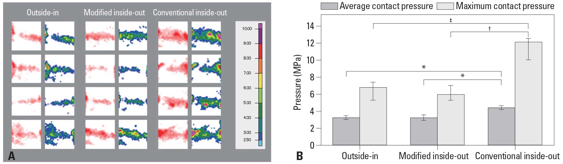
Fig. 6. (A) Scanned images (left rows) and converted images with the calibrated contact stress map (right rows) obtained from the pressure sensitive films for each technique. (B) The average and maximum contact pressure at the intra-articular aperture of the femoral tunnel for each technique. The values of the average and maximum contact pressure in the conventional inside-out group was significantly higher than that of the outside-in group (*p=0.012, †p=0.005) and the modified inside-out group (*p=0.012, ‡p=0.017). Error bars represent interquartile range.
Discussion
The causes of graft damage are multifactorial and can be related the type of graft, graft fixation and tensioning, as well as impingement of the graft against the surrounding structures.19 Another factor responsible for graft damage is repetitive bending stress on the graft at the intra-articular tunnel aperture.2,19-23 Regarding the tibial side, Bergfeld, et al.2 demonstrated that the tibial inlay technique prevents formation of an acute angle at the tibial attachment site known as the “killer turn angle”. Several authors have advocated the lateral approach rather than the conventional medial approach for transtibial tunneling.5,10,24,25 A biomechanical laboratory study by Kim, et al.4 demonstrated that anterolateral tibial tunneling leads to the lowest values for maximum shear stress and resultant forces at the interface between the graft and the killer turn.
The femoral graft-tunnel angle, which is formed between the graft and the intra-articular aperture of the femoral tunnel, also may contribute to increased attritional stress.5-7,24Although the inside-out technique for femoral tunneling can avoid potential injury to the extensor mechanism, especially the vastus medialis obliquus muscle and the medial patellofemoral ligament,9,11 several authors have alleged that this technique results in greater graft-tunnel angles.5-7 A cadaveric study by Handy, et al.6 showed that the inside-out technique for femoral tunnel placement leads to significantly sharper graft-tunnel angles than the outside-in technique. However, knee flexion was not strictly controlled in that study, which is drawback given that other surgeons advocate drilling in hyperflexion for the inside-out technique.7,10 Schoderbek, et al.7 recently expanded on the results of Handy, et al.6 by comparing the femoral graft-tunnel angle between the outside-in and inside-out techniques with 90° and 120° of knee flexion. Although use of the inside-out technique with the knee flexed 120° could produce a more obtuse graft-tunnel angle compared with the inside-out technique with 90° of knee flexion, it produced significantly lesser graft-tunnel angle than the outside-in technique.7
However, those studies involving measurement of the graft-tunnel angle only considered two dimensions (i.e., the sagittal plane) rather than three dimensions, and they failed to validate biomechanically that significant differences in the graft-tunnel angle affected the force exerted on the graft. To increase the femoral graft-tunnel angle, several modifications to femoral tunnel drilling have been introduced: 1) the knee is flexed 110°; 2) the proximal tibia is pushed backward as much as possible; and 3) the reamer is introduced through the far anterolateral portal.10 A clinical comparison study of the modified inside-out and outside-in techniques showed no significant side-to-side differences in posterior translation as measured by an arthrometer (modified inside-out: 2.38, outside-in: 2.10 mm; p=0.26) and Lysholm scores (modified inside-out: 90.6, outside-in: 90.0; p=0.72).11 In our 3D knee-model analysis, we found that the conventional inside-out technique produced significantly more acute femoral graft-tunnel angles than the other two techniques between 45° and 120° of knee flexion. This result is consistent with previous 2-dimensional studies.6,7 However, the femoral graft-tunnel angle for the modified inside-out technique was similar to that for the outside-in technique at all flexion angles. We believe that these results can be explained not only by the enhanced precision made possible with 3D-measurements, but also by the additional modifications to the surgical procedures that we considered (i.e., the knee was hyperflexed7 and the proximal tibia pushed backward).
Our data also showed that the tibial graft-tunnel angle was significantly greater than the femoral graft-tunnel angle at 120° of knee flexion for the conventional inside-out technique, but the other two techniques produced higher values for the femoral graft-tunnel angle than the tibial graft-tunnel angle at all knee flexion angles. This result suggests that with the conventional inside-out technique, the potential for graft injury due to the femoral graft-tunnel angle exceeds that due to the tibial graft-tunnel angle when knee flexion is 90° or greater, as suggested by previous researchers.2,3 However, our study showed no significant difference between the femoral graft-tunnel angle and the tibial graft-tunnel angle when the knee flexion was 90° after the conventional inside-out technique was used, as reported by Handy, et al.6 We found that the average tibial graft-tunnel angle was 100.7°, which was about 30° higher than the values reported in the previous study.6 We suggest there are two reasons for this higher value: 1) 2D-measurements may be less accurate than 3D-measurements, leading to underestimation of the true value of the tibial killer turn angle, and 2) compared to the conventional anteromedial tibial tunneling technique, the anterolateral tunneling technique we examined produces a tibial graft-tunnel angle that is less acute.4,5,24
Grafts can be exposed to abrasive force when they are stretched and turned acutely at the sharp edge of the tunnel.26 Papannagari, et al.27 used a 3D modeling technique to measure elongation of the PCL during in vivo knee flexion. They found that the end-to-end distance of the anterolateral (AL) bundle increased with increasing flexion and reached its maximum at 120° of flexion, at which point the length of the AL bundle was 34.7% greater than that at 0° of flexion (p=0.00014).27 A recent 3D modeling study by Jeong, et al.28 also showed that the PCL significantly increases in length as knee flexion increases between 0° and 135°, and the virtual AL fiber significantly increases in length between 0° and 90° of flexion (p < 0.05). Regardless of the tunneling technique, the femoral graft-tunnel angle in our study was greatest at 0° of knee flexion and tended to decrease towards 120° of knee flexion. However, we observed a sharper decrease in the femoral graft-tunnel angle for conventional inside-out group than for the other two groups, such that the femoral graft-tunnel angle was significantly more acute for the conventional inside-out group than the other two groups at 45° of knee flexion. This trend was even more apparent between 90° and 120° of knee flexion. These results suggest that the graft may be subject to increased stress at the graft-femoral tunnel interface when knee flexion exceeds 90°, and we suspect the force exerted on the graft around the intra-articular femoral aperture when knee flexion exceeds 90° is markedly higher with the conventional inside-out technique than the outside-in or modified inside-out techniques. In our cadaveric experiments using pressure-sensitive film, the same trends were observed as those observed in the 3D models of the graft-femoral tunnel. Data from this experiment confirm that the conventional inside-out technique for PCL reconstruction leads to higher average and maximum contact pressures than the outside-in or modified inside-out techniques. The pressure range of the Prescale LW film varies from 2.5 to 10.0 MPa, which indicates that the film can theoretically measure from a minimum pressure of 2.5 MPa to infinite pressure. The median value for maximum contact pressure with the conventional inside-out technique was 12.325 MPa, indicating that the actual pressure exceeded 10.0 MPa, regardless of whether this value was slightly over- or under-estimated. Even though the number of specimens was insufficient to provide statistical power to accept a null hypothesis, the difference between the conventional inside-out technique and the other two techniques could be considered as noteworthy.
Nonetheless, our study has several limitations. First, our 3D knee model did not reproduce the normal biomechanics of the knee. Also, we used static loading conditions without applying translational or rotational forces in the cadaveric experiments, which limits our ability to extrapolate the results to a clinical population. Further investigations are needed to determine the dynamic consequences of stress on the graft at the femoral tunnel aperture. Second, the small sample size limited the statistical power of the study. Nonetheless, the sample size was large enough to show a statistically significant difference among the groups. In addition, it should be noted that the methodology we adopted for the 3D model study was advantageous because it allowed us to collect data from the same subject under different experimental conditions (i.e., inside-out, outside-in and modified inside-out techniques), thus reducing the effects of intersubject variation. Third, comparisons of biomechanical inferiority of the acute tibial graft-tunnel angle in previous studies2,3 have shown that there is no definite evidence that smaller femoral
graft-tunnel angle and resultant increase in focal pressure at the articular orifice is related to early graft failure after reconstruction. Finally, the graft-tunnel angles were measured using the pin insertion sites on the tibia and femur that were considered to be the center of the virtual graft. However, the direction and tension of the graft might be affected by the contact osseous structures as well as the ACL. A study by Kim, et al.29 using a finite element model found that the lateral intercondylar tubercle of the tibia and the inner portion of the lateral femoral condyle play a major role in preserving the tension of the posterolateral bundle of the ACL. Future studies should assess the proper size of the virtual graft and interaction with surrounding structures.
In conclusion, the data from both our 3D knee-model analysis and cadaveric experiment indicate that the conventional inside-out technique leads to significantly more acute femoral graft-tunnel angle and higher stress at the intra-articular aperture of the femoral tunnel than the outside-in technique. However, the modified inside-out technique, in which the knee is flexed 110° and the proximal tibia is pushed back posteriorly, results in a femoral graft-tunnel angle and contact stress similar to the outside-in technique.
Acknowledgements
This study was supported by a faculty research grant of Yonsei University College of Medicine (6-2008-0241). The authors are grateful to Dong-Su Jang (Medical illustrator, Medical Research Support Section, Yonsei University College of Medicine, Seoul, Korea) for his help with the illustrations.
References
- McAllister DR, Miller MD, Sekiya JK, Wojtys EM. Posterior cruciate ligament biomechanics and options for surgical treatment. Instr Course Lect 2009;58:377-88.
- Bergfeld JA, McAllister DR, Parker RD, Valdevit AD, Kambic HE. A biomechanical comparison of posterior cruciate ligament reconstruction techniques. Am J Sports Med 2001;29:129-36.
- Markolf KL, Zemanovic JR, McAllister DR. Cyclic loading of posterior cruciate ligament replacements fixed with tibial tunnel and tibial inlay methods. J Bone Joint Surg Am 2002;84-A:518-24.
- Kim SJ, Shin JW, Lee CH, Shin HJ, Kim SH, Jeong JH, et al. Biomechanical comparisons of three different tibial tunnel directions in posterior cruciate ligament reconstruction. Arthroscopy 2005;21:286-93.
- Dunlop DG, Woodnutt DJ, Nutton RW. A new method to determine graft angles after knee ligament reconstruction. Knee 2004;11:19-24.
- Handy MH, Blessey PB, Kline AJ, Miller MD. The graft/tunnel angles in posterior cruciate ligament reconstruction: a cadaveric comparison of two techniques for femoral tunnel placement. Arthroscopy 2005;21:711-4.
- Schoderbek RJ Jr, Golish SR, Rubino LJ, Oliviero JA, Hart JM, Miller MD. The graft/femoral tunnel angles in posterior cruciate ligament reconstruction: a comparison of 3 techniques for femoral tunnel placement. J Knee Surg 2009;22:106-10.
- Kim SJ, Min BH. Arthroscopic intraarticular interference screw technique of posterior cruciate ligament reconstruction: one-incision technique. Arthroscopy 1994;10:319-23.
- Shino K, Nakagawa S, Nakamura N, Matsumoto N, Toritsuka Y, Natsu-ume T. Arthroscopic posterior cruciate ligament reconstruction using hamstring tendons: one-incision technique with Endobutton. Arthroscopy 1996;12:638-42.
- Kim SJ, Kim HK, Kim HJ. A modified endoscopic technique for posterior cruciate ligament reconstruction using allograft. Arthroscopy 1998;14:643-8.
- Kim SJ, Shin SJ, Kim HK, Jahng JS, Kim HS. Comparison of 1- and 2-incision posterior cruciate ligament reconstructions. Arthroscopy 2000;16:268-78.
- Tuan HS, Hutmacher DW. Application of micro CT and computation modeling in bone tissue engineering. Comput Aided Des 2005;37:1151-61.
- Victor J, Van Doninck D, Labey L, Innocenti B, Parizel PM, Bellemans J. How precise can bony landmarks be determined on a CT scan of the knee? Knee 2009;16:358-65.
- Apsingi S, Bull AM, Deehan DJ, Amis AA. Review: femoral tunnel placement for PCL reconstruction in relation to the PCL fibre bundle attachments. Knee Surg Sports Traumatol Arthrosc 2009; 17:652-9.
- Lee YS, Ra HJ, Ahn JH, Ha JK, Kim JG. Posterior cruciate ligament tibial insertion anatomy and implications for tibial tunnel placement. Arthroscopy 2011;27:182-7.
- Pearsall AW 4TH, Pyevich M, Draganich LF, Larkin JJ, Reider B. In vitro study of knee stability after posterior cruciate ligament reconstruction. Clin Orthop Relat Res 1996:264-71.
- Burns WC 2nd, Draganich LF, Pyevich M, Reider B. The effect of femoral tunnel position and graft tensioning technique on posterior laxity of the posterior cruciate ligament-reconstructed knee. Am J Sports Med 1995;23:424-30.
- Allaire R, Muriuki M, Gilbertson L, Harner CD. Biomechanical consequences of a tear of the posterior root of the medial meniscus. Similar to total meniscectomy. J Bone Joint Surg Am 2008; 90:1922-31.
- Iriuchishima T, Tajima G, Ingham SJ, Shen W, Smolinski P, Fu FH. Impingement pressure in the anatomical and nonanatomical anterior cruciate ligament reconstruction: a cadaver study. Am J Sports Med 2010;38:1611-7.
- Natsu-ume T, Shino K, Nakata K, Nakamura N, Toritsuka Y, Mae T. Endoscopic reconstruction of the anterior cruciate ligament with quadrupled hamstring tendons. A correlation between MRI changes and restored stability of the knee. J Bone Joint Surg Br 2001;83:834-7.
- Toritsuka Y, Shino K, Horibe S, Mitsuoka T, Hamada M, Nakata K, et al. Second-look arthroscopy of anterior cruciate ligament grafts with multistranded hamstring tendons. Arthroscopy 2004; 20:287-93.
- Segawa H, Koga Y, Omori G, Sakamoto M, Hara T. Influence of the femoral tunnel location and angle on the contact pressure in the femoral tunnel in anterior cruciate ligament reconstruction. Am J Sports Med 2003;31:444-8.
- Shearn JT, Grood ES, Noyes FR, Levy MS. One- and two-strand posterior cruciate ligament reconstructions: cyclic fatigue testing. J Orthop Res 2005;23:958-63.
- Ohkoshi Y, Nagasaki S, Yamamoto K, Urushibara M, Tada H, Shigenobu K, et al. A new endoscopic posterior cruciate ligament reconstruction: minimization of graft angulation. Arthroscopy 2001;17:258-63.
- Kim SJ, Chang JH, Kang YH, Song DH, Park KY. Clinical comparison of anteromedial versus anterolateral tibial tunnel direction for transtibial posterior cruciate ligament reconstruction: 2 to 8 years’ follow-up. Am J Sports Med 2009;37:693-8.
- Nishimoto K, Kuroda R, Mizuno K, Hoshino Y, Nagamune K, Kubo S, et al. Analysis of the graft bending angle at the femoral tunnel aperture in anatomic double bundle anterior cruciate ligament reconstruction: a comparison of the transtibial and the far anteromedial portal technique. Knee Surg Sports Traumatol Arthrosc 2009;17:270-6.
- Papannagari R, DeFrate LE, Nha KW, Moses JM, Moussa M, Gill TJ, et al. Function of posterior cruciate ligament bundles during in vivo knee flexion. Am J Sports Med 2007;35:1507-12.
- Jeong WS, Yoo YS, Kim DY, Shetty NS, Smolinski P, Logishetty K, et al. An analysis of the posterior cruciate ligament isometric position using an in vivo 3-dimensional computed tomography-based knee joint model. Arthroscopy 2010;26:1333-9.
- Kim HY, Seo YJ, Kim HJ, Nguyenn T, Shetty NS, Yoo YS. Tension changes within the bundles of anatomic double-bundle anterior cruciate ligament reconstruction at different knee flexion angles: a study using a 3-dimensional finite element model. Arthroscopy 2011;27:1400-8.
![]()