

Article
Related Links
R. Zdero, PhD,*,† P. V. Fenton, MD, FRCP(C),‡ J. Rudan, MD, FRCS(C),§ and J. T. Bryant, PhD, PEng*,†
Abstract
This article describes tibiofemoral contact area measurement results from tests on 1 commercial total knee arthroplasty (TKA) using 2 experimental methods— fuji film and diagnostic ultrasound. The study presents a novel diagnostic ultrasound technique developed specifically for measuring TKA contact areas. Because most experimental investigations have been concerned with interimplant comparison, this article is one of few parametric TKA studies in the literature. Fuji film and ultrasound provide lower and upper bound contact area measurements based on their physical operating principles; this implies that no single measurement method can be relied on exclusively to glean contact area data. Designers should be cautious in using contact area and contact stress as the exclusive predictors of TKA failure.
Keywords: – contact area, contact stress, total knee arthroplasty, ultrasound, fuji film
Introduction
Fixed-bearing total knee arthroplasties (TKAs) are composed mainly of noncongruent metal-on-plastic mating components used in resurfacing worn cartilage in patients with arthritis. Ultra-high molecular weight polyethylene (UHMWPE) components of TKAs wear under degradation mechanisms often associated with polyethylene fatigue under high contact stresses [1–5]. The corresponding interfacial tibiofemoral contact areas can be categorized as area, line, point, or quasiline in shape [6] and are related to tibiofemoral geometric congruency.
To assess indirectly the average contact stress during TKA articulation, measuring contact areas in vitro commonly has been done with pressure-sensitive fuji film [2,4,5,7]. Although fuji film is appealing because of its simplicity, low cost, and rapidity of use, its disadvantages are disruption of natural mating at a TKA interface, its limitation to 2-dimensional static in vitro use, and minimum pressure threshold required for detection of contact. A new diagnostic ultrasound technique previously was developed to eliminate these drawbacks; the main advantage of ultrasound is its nonintrusivity [8]. The main disadvantages of ultrasound are the time costs associated with calibration and image analysis.
It is hypothesized that surface deformation incurred in the contact region by polymer tibial components results in an outer ring of plastically deformed material, which would be detected differently by ultrasound and fuji film, due to the physical operating principles of each method (Fig. 1). Specifically, ultrasound would overestimate contact area because of proximity artifact, whereas fuji film would underestimate actual contact because of its pressure threshold and film thickness. This difference ultimately results in ultrasound and fuji film providing upper and lower bound solutions for contact contact area. This article describes the application of this imaging tool and standard fuji film in measuring contact areas for a commercially available TKA.
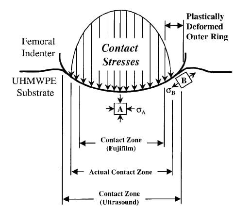
Fig. 1. Bounding a contact area solution. Ultrasound and fuji film tend to overestimate and underestimate the actual contact area by virtue of the physical principles on which they are based. Surface element A undergoes compressive stress, σA, whereas tangential tensile stress, σB, at the edges of the actual contact region may plastically deform surface element B. UHMWPE, ultra-high molecular weight polyethylene.
Experimental Setup
The experimental procedure used to measure TKA contact areas in this study is described briefly. Greater details can be found elsewhere [8].
Ultrasound Tests
As shown in Fig. 2A, a loading jig was constructed for testing a commercial Omnifit Series 7000 total right knee (size 7) from Osteonics (Allendale, NJ) at 3 flexion angles (0°, 20°, and 60°) and 3 axially compressive loads (281 N, 1,115 N, and 2,073 N). Tests were performed at an average water bath temperature of 22.5°C. The loading jig and TKA were submerged in a water tank. A 7.5- MHz linear ultrasound probe (Sonoline SL2 from Siemens, Munich, Germany) was traversed linearly in 1-mm increments overtop the TKA, obtaining 20 to 25 image slices per load-angle pair. Image slices were recorded on videotape using Digital Video Producer Software (Intel Canada, Ottawa, Ontario) and analyzed to obtain acoustic intensity traces, or gray-level distributions (GLDs), along the tibiofemoral interface using SigmaScanPro software (Jandel Scientific, San Rafael, CA). Each GLD trace was transferred to a commercial spreadsheet and smoothed using a fourth-order zero-lag Butterworth algorithm with a signal-to-noise ratio of 10. Contact width measurements from each slice were obtained, ultrasound correction factors were applied, and 2-dimensional contact area maps were reconstructed by overlaying the results of the individual images using commercial spreadsheet software (Fig. 2B).
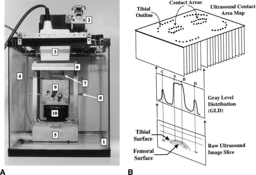
Fig. 2. Ultrasound TKA scanning technique. (A) Experimental apparatus shows (1) water tank, (2) 2-dimensional translation stage, (3) ultrasound probe, (4) thermometer, (5) aluminum frame, (6) tibial insert, (7) ultra-high molecular weight polyethylene tibial insert, (8) alignment bolts, (9) cobalt-chrome femoral component mounted onto aluminum block, and (10) inflatable rubber bellow. (B) Contact area map reconstruction from raw ultrasound images and their gray-level distributions (GLDs). From the GLDs, the contact width A–B and tibial insert width C–D for each image slice may be identified.
Fuji Film Tests
For comparison, TKA tests were performed using fuji film. The pressure film used was the Fuji prescale ultra super-low grade with a 0.2 to 0.6-MPa pressure range and 20° to 35°C operating temperature range, being halfway through its 2-year shelf life [9]. The average ambient room temperature during trials was measured at about 23.2°C under dry test conditions.
Each fuji film patch result was scanned at 1,500 dpi using a ScanJet IIcx flatbed scanner (Hewlett Packard, San Diego, CA) and Aldus PhotoStyler 2.0 software (Microsoft, San Jose, CA). The contact patch scans were analyzed using SigmScanPro software to quantify the total contact area and were aligned onto an outline of the UHMWPE component for proper registration with respect to the tibial outline.
Statistical Design of Tests
The TKA was subjected to compressive axial loads of 281, 1,1
15, and 2,073 N (63, 250, 465 lb) at 3 flexion angles (0°, 20°, 60°) for 9 possible loadangle pairs. For ultrasound and fuji film, 8 loadangle configurations were tested and replicated twice (n = 2). To increase the statistical power of the design moderately, the middle load-angle pair (1,115 N–20°) was replicated 3 times (n = 3). In total, there were 38 tests, 19 order-randomized experiments for each technique on 1 TKA specimen only.
Constructing and Analyzing 2-Dimensional Contact Area Maps
Once the ultrasound and fuji film data were obtained, a series of top view maps were constructed for corresponding load-angle pairings, as shown in Fig. 3. Specific measured and calculated quantities related to contact area are tabulated in Fig. 3. Results from each method were not obtained simultaneously but were corresponding load-angle pairs from the randomized experiments.
In contrast to the fuji film method, ultrasound contact areas presented in the current paper are 2-dimensional undeveloped projections of a 3-dimensional surface area and do not take into account the curvature of the tibial surface. These undeveloped projected areas are used for all subsequent average contact stress calculations and statistical analyses for the ultrasound technique. Fuji film paper conforms to the tibial curvature during tests and physically is unfolded onto the horizontal for analysis. Contact areas reported for fuji film are developed or unfolded surface areas. Despite this geometric difference in techniques, ultrasound and fuji film comparison is valid as shown by the minimal differences between ultrasound undeveloped area measurements and ultrasound developed area calculations.
Although the anterior tibial perimeter sometimes was difficult to discern with ultrasound, in all cases the posterior margins were much clearer, allowing for easy detection of reference points and proper registration of contact patches. The intercondylar midsection of the component was not imaged because no contact occurred there. The far medial and lateral margins of the maps lack data because, during scanning, the ultrasound beam became tangent to the tibia, yielding no useful information. In contrast, fuji film was not capable of detecting the tibial perimeter because of the lack of tibiofemoral contact there.
Statistical analysis of variance (ANOVA) with the SAS System (SAS Institute Inc, Cary, NC) was used to obtain 95% confidence intervals of the difference in total contact area means for comparing the effect of 2 given parameters. Specifically, ANOVA was used to assess the individual effects of changing flexion angle, compressive load, mediolateral side, and measurement method on contact area. Type I error was corrected by the program using Tukey’s HSD (honest significant difference) method.
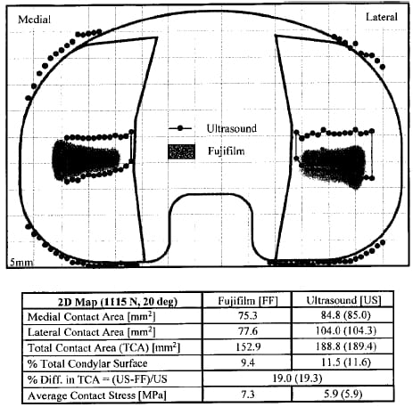
Fig. 3. Contact area map (1,115 N, 20°) showing fuji film (shaded patches) and ultrasound contact areas superimposed together. The outer edges of the tibial insert also are detected with ultrasound scanning. The values in parentheses are the developed areas for ultrasound for appropriate comparison with fuji film.
Results and Discussion
Contact Area Shape
As shown in Fig. 3, both methods indicated a quasiline contact in the mediolateral direction, being consistent with previous fuji film studies on the Omnifit TKA at similar loads and flexion angles [3]. Patches characteristically were tapered toward the tibial eminence, most likely caused by deflection of the aluminum-polymer support plate. This finding was different from previous studies, which used rigid boundary support conditions during compressive loading [3–5]. It is probable, however, that boundary conditions of the metal tibial tray, which supports the polymer insert in vivo, allow for some deflection, yielding tapered contact areas [8].
The contact patch aspect ratios (mediolateral length to anteroposterior length) for both methods were comparable for a given load-angle test setting and averaged 2.4 for all data combined. These Omnifit contact patches are oriented mediolaterally as in Manley et al [3]. More specifically, the fuji film aspect ratio was 2.8, whereas ultrasound averaged 2.0, indicating the more linelike nature of the fuji film results.
Finally, although the fuji film yielded continuous and smooth patches, ultrasound yielded discontinuous patches, which were truncated medially and laterally. Although these discontinuities can be attributed to small air bubbles, impurities in the water or polymer, signal noise, and surface roughness, the incremental nature of 2-dimensional ultrasound scanning and the fact that curve fitting the data was not used are primary factors.
Contact Area Position
Contact patches for both measurement methods typically were located centrally in the anteroposterior direction on the condyles (Fig. 3). This location was as expected because, at this position, the sagittal curvature of the tibia is at a minimum, meaning that the femur most readily would settle or align itself there. In the mediolateral direction, about two thirds of the patches are positioned symmetrically, which corresponds to the intent of the manufacturer [3], whereas the remainder show a slight lateral shift. This shift may be due to slight asymmetry in the loading mechanism used.
Contact Area Size
Fig. 4 illustrates changes in total contact area with flexion angle and compressive load for all maps obtained. Each datum point gives a total weightbearing area, which is the sum of medial and lateral contact area, for a given load-angle configuration and represents the average between replicates of the same load-angle pair.
Flexion Angle. Based on 95% confidence intervals, total contact areas at 0° and 20° of flexion showed no statistical difference regardless of method or load. Conversely an actual decrease in total contact area of approximately 60 mm2 occurred as the knee was flexed from 0° to 20° to 60°. This decrease suggested that, for this TKA design, maximal conformity and greatest contact area occurs at low flexion corresponding to heel-strike (5°) and the stance phase of gait (15°–25°), that is, when the knee experiences the greatest load. Similarly the TKA was designed with only minimal congruency for situations when the knee is not loaded as greatly, such as during swing phase (55°–70°) [3,10 –12]. As such, high joint forces during high flexion activities, such as stair climbing and sitting, occur when the contact area is small.
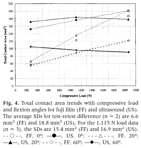
Compressive Load. For fuji film, a linear relationship between increased load and total contact area was evident. Patch sizes increased from 55 to 200 mm2, indicating increased polymer surface deformation at the tibiofemoral interface. For ultrasound, however, there was no such statistical change discernible from the 95% confidence intervals in total surface area engaged with rising compressive force. It is conceivable that although increased loads increase the depth of femoral penetration into the polymer, the contact width (projected along the horizontal) may not change significantly; this may be possible during deflection of the nonrigid polymer support plate against which the tibial component rests. Ultrasound measurements of the projected area remain the same regardless of load, whereas fuji film, because it measures the actual 3-dimensional surface area, yields increasing areas with load. This phenomenon may be closer to in vivo boundary conditions than the use of a rigid foundation.
Measurement Method. The modalities yielded statistica
lly different areas based on 95% confidence intervals, with ultrasound reporting total contact areas 26 to 47 mm2 larger than fuji film regardless of angle or load.
Mediolateral Side. The same trends as with total contact area results were found for medial and lateral contact patches individually with respect to the effects of flexion angle, compressive load, and measurement method. Although it is known that normal anatomic knees preferentially load the medial condyle, this may not always be the case for prosthetic knees. For TKAs, mediolateral symmetry depends on lower limb alignment (something beyond the scope of the current study) and the geometries of the articulating surfaces. In the case of the present Omnifit TKA tested, there was no significant difference between medial and lateral contact areas. This result agrees with the previous fuji film tests of Manley et al [3], who verified experimentally the intended mediolateral symmetry of the Omnifit implant. They performed their tests at 669 N (150 lb) of compressive load, 2 flexion angles (15° and 90°), and with 1 mm mediolateral malalignment. None of the other 10 commercial designs tested by Manley et al showed equal mediolateral load distribution, indicating the unique geometric characteristics of Omnifit’s articulating surfaces.
Average Contact Stress
Using the total contact areas, corresponding average contact stresses were calculated. Fig. 5 illustrates the change in average contact stress with flexion angle and compressive load. Consideration of UHMWPE’s elastic limit at room temperature (10–15 MPa), the onset of plastic deformation under compression (15–22.5 MPa), and complete plastic flow (30–45 MPa) revealed several important details [13]. Over the entire load range and for both measurement techniques, flexion of the knee from 0° to 20° did not change contact stress but was followed by a steep rise from 20° to 60°. The consequence of similarly high congruity at 0° and 20° is that stresses are lower for the high load events of heel-strike (5°) and full 1-legged stance (15°–25°). In these cases, the stresses are <15 MPa, indicating that the polymeric condyles likely are undergoing only elastic deformation at the outer zones of the contact area.
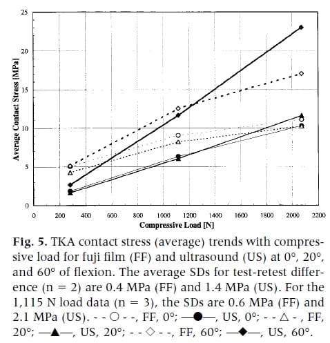
Conversely, at 60°, the contact pressure rises dramatically into the plastic region for 2,073 N (465 lb). If recipients of a TKA subject their knees to activities that are high impact and require moderate levels of flexion (eg, skiing, running, stair climbing), the polymer components may sustain plastic damage. Low-impact activities performed frequently (eg, walking) eventually may cause fatiguing of the material, even though the tibial condyles are well below the elastic yield point at 0° and 20°. In both cases, fatigue-related wear, such as pitting and delamination, may occur [1,2].
Bounding the Contact Area Solution
The current working hypothesis is that ultrasound overestimates and fuji film underestimates actual contact area, providing upper and lower bound solutions. This hypothesis can be explained by the physical operating principles of each method and the tangential surface stresses incurred by the polymer component (Fig. 1).
Fuji film underestimates the contact zone because of the minimum pressure threshold of 0.2 MPa that must be reached before detection of any contact. Its 0.2-mm thickness also interferes with proper TKA mating, increases the distance between components, and leads to lower component congruency and smaller contact area. For example, high congruency implants, with intercomponent gaps smaller than film thickness, result in a ringlike contact patch (AS Greenwald, personal communication, May 1999). More central regions do not come into contact at all because of jamming of fuji film at the periphery. The amount of underestimation depends on the pressure distribution at the outskirts of the contact region. If the pressure gradient is shallow such that pressures near the edges are below the 0.2 MPa threshold, the fuji film error is greater and vice versa, as shown in Fig. 1.
For ultrasound, the lack of such intrusivity means that maximal TKA congruency and proximity occurs, ensuring larger contact area. In addition, this method is susceptible to proximity artifact, in which ultrasound detects contact in regions where mating surfaces are highly congruous and in close proximity, but without being directly engaged.
These effects may be exacerbated by surface tangential stresses, which could surpass the elastic yield point for UHMWPE [14], resulting in a plastically deformed outer ring around the contact area. Because the outer ring material deforms to the contour of the femoral component, it would have negligible contact stress. Fuji film would detect this region poorly because stresses are below its minimum pressure threshold, underestimating contact. Ultrasound would detect the outer ring, however, because of its proximity artifact, providing an upper bound value.
Comparison With Previous Studies: Contact Area Size
Fig. 6 shows the results of previous experimental Omnifit TKA studies for total weight-bearing contact area with compressive load [3–5,13]. These results are plotted with the current results from fuji film and ultrasound.
First, the present study’s contact area sizes, 90 to 201 mm2 for ultrasound and 55 to 202 mm2 for fuji film, are comparable to those of previous investigators for loads up to 2.1 κN (64.5–200 mm2). A similar upward trend with compressive load is observed in all results, with the exception of ultrasound at 60° flexion.
Second, Stewart et al [13] performed tests over a wide load range (250 –2,500 N) at 0° flexion for an unidentified stabilized cruciate-retaining implant, the same categorization as the Omnifit. The linear trend in their data is similar to current fuji film results, being close at 0° and 20° flexion over the same load range. Although similar linearity was not found between current ultrasound area trends and the results of Stewart et al [13], total contact area ranges are comparable.
Third, other studies performed fuji film tests with the Omnifit [3–5] covering a load range (669 –2,000 N) similar to the present one (281– 2,074 N). Although a wide range of flexion angles was used (15°, 60°, 90°), their resulting contact areas (64.5–130 mm2) were much smaller than the present study’s except in the case of 60° (55–121 mm2). Specifically a comparison between the data from Szivek et al [4,5] at 60° of flexion and 2 κN (average area = 87 mm2) and the present fuji film results (area = 121.5 mm2) reveals a 28% difference in total contact area. This difference is larger than typical measurement errors of 10% to 15% for this method [15], indicating that the difference is due to something more fundamental.
There are 2 contributing factors to this difference— boundary conditions and fuji film pressure sensitivity. First, Szivek et al [4,5] and Manley et al [3] laterally constrained their tibial inserts (with their metal trays) by potting them into support blocks. In the present study, the tibial components (without their metal trays) were loaded against a semirigid UHMWPE support plate (0.9 mm deflection at 2 κN) and allowed to self-align during loading. During loading, the lack of lateral constraints would allow for tibial tray lift-off at its edges away from its support plate, which is a well-known phenomenon [16,17]. The nonrigid support plate would permit some tibial insert deflection. Both of these would cause a contouring of the tray around the rigid femoral components, increasi
ng the contact area. The current boundary conditions may be closer, however, to in vivo tibial insert behavior than those of other investigators, who use a rigid support base that allows for negligible deflection. The in vivo conditions may allow for some deflection at the center of the condyles because of the boundary conditions created by the cortical bone, trabecular bone, and metal stem.
Second, Szivek et al [4,5] reported that they used a type of fuji film with a minimum sensitivity of 9.8 MPa. Manley et al [3] did not report the pressure sensitivity range of the fuji film grade used. The present study used an ultralow grade film with a lower 0.2 MPa threshold that better detects the low contact stress regions on the outer ring of a contact patch, resulting in larger contact areas. To illustrate this effect, consider a rectangular contact patch of 100 mm2 with a 2:1 aspect ratio measured by low-sensitivity fuji film. This patch is 7.07 mm x 14.14 mm in size. Using a more sensitive fuji film grade, an additional 1 mm outer ring of articulating material might be detected. The more sensitive fuji film would yield the larger contact patch dimensions of 9.07 mm x 16.14 mm (= 146 mm2), an area increase of 46%.
Finally, regarding temperature effects, for their tests at 37°C and 2 κN, Szivek et al [4] showed an increase in contact area from a flexion angle of 0° to 15°, followed by a drop at 60°. This trend is consistent with the present results for fuji film and ultrasound tests. The current contact areas are much larger, however, than the areas of Szivek et al [4], even though they operated at a higher temperature. The increased temperature would be expected to lower the Young’s modulus of UHMWPE making it softer, increasing their contact areas. Tibial insert boundary conditions and the different fuji film pressure thresholds used would account for this difference. The effects of temperature are not evident in comparing the results from Szivek et al [4] and Szivek et al [5] for 15° tests at 2,000 N because the contact areas are almost the same. Temperature effects were pronounced for their 60° tests, however. Because the same experimental procedures were used in both studies by Szivek et al, this inconsistency may be accounted for by typical 10% to 15% fuji film experimental scatter [15].
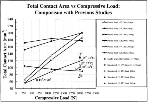
Fig. 6. Comparison of total contact areas from previous TKA studies with present fuji film (FF) and ultrasound (US) results. Most previous studies use the fuji film technique for testing commercial implants.
Contact Area and Stress as Total Knee Arthroplasty Design Criteria
The literature usually recommends enlarging contact area and reducing contact stress to diminish wear [3]. Often overlooked is the survival of many implants despite expectations otherwise based on high 40- to 60-MPa contact stresses calculated from finite element models [18] and 10- to 35-MPa stresses from fuji film tests [3,5]. These are beyond the 10- to 15-MPa material yield point of tibial polymer inserts [13]. This study suggests, however, that contact areas occurring in vivo may be larger than sometimes predicted, suggesting caution in using contact stress exclusively as a design criterion. Other factors should be considered, such as movement of the contact point across tibial surfaces [14], for which ultrasound’s real-time imaging capabilities may be well suited.
Conclusions
- New ultrasound technique: The results of a new method for detecting 2-dimensional, in vitro, TKA contact areas have been presented, whose key feature is its nonintrusive nature and its potential as a commercial TKA design tool.
- Parametric study: Because previous studies usually considered interdesign comparison of several TKAs, to our knowledge, the current study is one of few parametric investigations performed to date on a single commercial TKA.
- Contact areas: Ultrasound tests yield larger TKA contact areas than fuji film, averaging 36.3 mm2 over the range of flexion angles and compressive loads. Contact areas measured from both methods ranged from 55 to 202 mm2; fuji film results were related linearly and positively to applied load, whereas ultrasound areas were unaffected; and both methods showed enlarged areas as flexion angle increased. Differences in contact area between medial and lateral condyles were not present, being consistent with the manufacturer’s intended symmetry of the implant.
- Bounding the contact area solution: Ultrasound and fuji film yield upper and lower bound solutions of total contact area because of the operating principles of each method and tangential surface stresses that can cause an outer ring of plastically deformed material. Because every technique is an indirect measure of the gap between the mating parts due to its limited resolution, bounding the contact area solution using several methods rather than with any single technique should be considered.
- Fuji film use: Previous studies sometimes have used films with relatively high pressure thresholds (eg, 9.8 MPa), underestimating the actual contact area. As such, it is recommended that fuji film grades with low pressure thresholds be used for maximal detection of TKA total contact area engaged.
- Contact stress criterion: A common clinical occurrence is the survival of TKAs that were predicted to fail because of the presence of small contact area and high contact stresses. As such, contact stress as the exclusive predictor of TKA failure should be used with caution.
Acknowledgment
We extend thanks to Gerry Saunders and David Siu (Human Mobility Research Centre, Kingston General Hospital, Kingston, ON, Canada), for their technical expertise; Queen’s StatLAB (Queen’s University, Kingston, ON, Canada), for help in the statistical design of the tests; and Dr. Mark Kester and Osteonics Corporation (Allendale, NJ, USA), for infrastructure support.
References
- Cornwall GB: Kinematic conditions of contact and wear of ultra high molecular weight polyethylene in total joint replacements. PhD Thesis, Mechanical Engineering Department, Queen’s University, Human Mobility Research Centre, Kingston, Ontario, 1996
- Cornwall GB, Bryant JT, Hansson CM, et al: A quantitative technique for reporting the surface degradation patterns of UHMWPe components of retrieved total knee replacements. J Appl Biomater 6:9, 1995
- Manley MT, Kester M, Averill RG: Femoro-tibial contact area: comparison of contemporary total knee prosthetic systems. Osteonics Corporation, Allendale, NJ, 1990
- Szivek JA, Cutignola AM, Volz RG: Tibiofemoral contact stress and stress distribution evaluation of total knee arthroplasties. J Arthroplasty 10:480, 1995
- Szivek JA, Anderson PL, Benjamin JB: Average and peak contact stress distribution evaluation of total knee arthroplasties. J Arthroplasty 11:952, 1996
- Pappas MJ, Makris G, Buechel FF: Contact stresses in metal-plastic total knee replacements: a theoretical and experimental study. Internal Report No. 003, Biomedical Engineering Corp, South Orange, NJ, January 23, 1986
- Liggins AB, Finlay JB: Recording contact areas and pressures in joint interfaces. 71. In Little EG (ed): Experimental mechanics: technology transfer between high tech engineering and biomechanics. Elsevier Science Publishers, Amsterdam, p. 71
- Zdero R: A new diagnostic ultrasound technique for studying TKR contact mechanics. PhD Thesis, Department of Mechanical Engineering, Queen’s University, Kingston, Ontario, May 1999
- Heim CS, Postak PD, Greenwald AS: Factors influencing the longevity of UHMWPE tibial components: series II. Orthopaedic Research Laboratories, Cleveland, OH, 1997
- Deluzio KJ: Modelling and analysis of gait waveforms. PhD Thesis, Department of Mechanical Engineering, Queen’s University, Kingston, Ontario, 1997
- Laskin RS: Biomechanics of the knee. p. 52. In Replacement of the knee. Springer-Verlag, Berlin, 1984
- Norkin C: Gait, joint structure function. FA Davis, Philadelphia, p. 395-444, 1985
- Stewart T, Shaw D, Auger DD, et al: Experimental and theoretical study of the contact mechanics of five total knee joint replacements. Proc Inst Mech Eng 209:225, 1995
- Bartel DL, Bicknell VL, Wright TM: The effect of conformity, thickness, and material on stresses in ultrahigh molecular weight components for total joint replacement. J Bone Joint Surg Am 68:1041, 1986
- Hale JE, Brown TD: Contact stress gradient detection limits of pressensor film. J Biomech Eng 114:352, 1992
- Keer LM, Silva MAG: Two mixed problems for a semi-infinite layer. J Appl Mech 1121, December, 1972
- Keer LM, Dundurs J, Tsai KC: Problems involving a receding contact between a layer and a half space. J Appl Mech 1115, December, 1972
- Bartel DL, Rawlinson JJ, Burstein AH, et al: Stresses in polyethylene components of contemporary total knee replacements. Clin Orthop 317:76, 1995
![]()