Joshua Jones – ME (Lead), Andrzej Lubaszka EE
Jenna Kilroy – ISE, Whitney Domigan ME
1. Abstract
The primary goal of this Senior Design project is to examine a low energy, non-thermal fuser that is capable of fusing toner to paper without the use of heat. This fuser will use pressure only and be able to be retrofitted to existing printers to be used in locations where power supply is limited. Two fuser assemblies will be constructed for evaluation. The first design will be a four-roller cold pressure fuser that applies the pressure using parallel rollers. The second design will also be a four-roller cold pressure fuser however the pressure will be applied using two skewed rollers. These two different designs will help determine the most effective way to apply a uniform pressure across the nip without damaging the paper as it passes through the fusing system.
This paper’s purpose is to thoroughly explain the concept selection and design process used as well as our testing and validation method.
2. Nomenclature
Nip: place of intersection where one roller contacts the other
Calendar: to make the surface of paper smooth by pressing it between two rollers [1]
3. Introduction
In the xerographic process, elastopolymer toner is first applied to the paper in the shape of the desired image. The toned paper is then passed through a fuser, which is responsible for permanently adhering the toner to the paper. While “cold pressure” fusing has been explored in the past, heat based fusing is most prevalent today [2].
Heat based fusing is accomplished by heating a pair of rollers through which the toned paper passes [Figure 1]. The contact pressure of the rollers is on the order of 100 PSI, as heat provides the energy required for the toner to melt and become fused with the paper [2]. “Cold pressure” using trades heat for pressure, relying on pressure lone to fuse the toner to the paper.
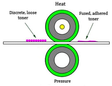
Figure 1: How a Traditional Fuser Works [1]
The objective of this project has been to reconsider the design of a low power fuser. In order to provide maximum benefit to the client, Xerox, this would have involved producing a low power fusing technology that produces quality prints, and could easily be integrated into existing products, namely the Xerox WorkCentre series printers. However, due to time constraints the primary goal of this project changed to producing a viable prototype that demonstrated that cold pressure fusing was possible at a size that would work in an office sized printer, and through testing, develop a model of how design parameters affect print quality.
Based on existing information about cold pressure fusing, it was known that standard toner requires about 7,000 PSI in order to fuse, whereas paper begins to calendar at about 200 PSI. This pressure differential presents a significant hurdle to cold pressure fusing. Some degree of calendaring of the paper is tolerable, but high pressures also tend to damage the paper in other ways, such as creasing and tearing. Knowing this, Xerox decided to resolve this issue with other projects, and that this project should focus on producing a uniform high pressure across the nip. Pressure sensitive film would be used as a substitute for an unfused print in order to evaluate pressure uniformity. The correlation of pressure senseitive film to fusing success will be discussed in the conclusions.
While integrating the new fuser into existing products was a long-term goal, the 20 week timespan of this project did not allow enough time to invest in installing the device into a printer. However, in order to facilitate later integration, the design was sized to fit in the same area of existing fusers, and drive train integration was considered.
As the actual device produced by this project would fall short of the long-term goals, developing an accurate model of how the various design parameters affect print quality became important. This model will enable future projects to utilize the information learned through this project to roduce a more commercially viable low energy, on-thermal fuser.
4. Process
Assumptions Made:
Throughout the design process, especially during the analysis phase, a number of assumptions were made. One of the major assumptions made in order to simplify the analyses is bottom roller, with a 2” diameter, has negligible deflection, compared to the deflection of the middle roller, when loaded. This statement implies that all detrimental deflection of paper contacting rollers stems from the middle 1.5” roller. This assumption was made by using the information available in several existing cold pressure fusing patents including patent 381,814 [3] and 387,061 [4]. It was also assumed that standard 24 lb weight paper is used.
Finally, the final design assumes the addition of the top two rollers decreases the deflection of the middle roller and generates a more uniform pressure at the nip. This assumption was made by using the information available in several existing cold pressure fusing patents including patent 81,814 [3] and 387,061 [4] and further explored hrough later analyses.
Concept Selection Process:
For this project the PUGH concept selection process was used. This selection process uses a scoring matrix that helps determine which designs are “better” then others. Options are assigned scores passed on pluses and minuses relative to a specific set of design criteria. For this project the design criteria off Xerox’s needs and requirements. Each design was evaluated against a datum, or reference concept. Throughout our design process we utilized this concept selection process three times.
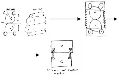
Figure 2: PUGH Selection Process
The first PUGH matrix compared 14 designs against a tradition two-roller cold pressure fuser. During this first PUGH process a wide variety design were considered such as ultrasonic welding, stamping processes and multi roller designs. Based on primarily on size and potential to cause paper damage, all designs except those featuring multiple rollers were eliminated.
The second PUGH matrix focused on determining how many rollers would be most useful. During this second selection process the team looked at two-roller, three-roller and four-roller designs with various forms of loading. These designs were compared against a basic two-roller design that was spring loaded at the ends of the rollers. We eliminated all but one design based on the design’s abi
lity to apply a uniform load, the stability of the load and the potential to damage the rollers or paper. Based on this PUGH matrix the four-roller design system was selected.
The third PUGH matrix was used to determine how to mechanically load the four-roller design. For this final PUGH matrix four different ways of loading the system were compared against the datum, which was two end plates connected by screws. Based on the criteria none of the four designs scored high enough to be selected herefore the team decided to use the datum as the method of loading the system.
Detailed Design:
Based on the PUGH Concept Selection the team decided to utilize a four-roller system. The design will consist of one larger bottom roller that is 2 inches in diameter and 13 inches long, a smaller center roller that is 1.5 inches in diameter and 13 inches long and 2 top rollers that are 1 inch in diameter and 13 inches long. The load will be applied through the top 1-inch roller and the bottom 3-inch rollers using captive screws that connect the two end plates together. The middle 1.5-inch roller does not have any load directly applied to it. By not applying the load directly to the middle roller we will be able to minimize the deflection of the middle roller.
To stabilize the system four stabilizing bars, were attached with two on each side. The bottom 3-inch roller is used to drive the system. This bottom roller has a shaft with a 0.5-inch diameter that is attached to a coupler that is then attached to the motor. Figure 4 shows the coupling schematic. igure 3 shows the detailed Auto CAD drawing of he final fuser system.
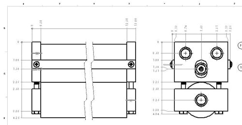
Figure 3: Final Assembly Drawing
Engineering Calculations and Analysis:
Engineering analyses were conducted prior to the finalization of the product to predict the design performance. One common problem area for pressure fusers is roller deflection because the high loads necessary to generate high pressure creates a large bending moment on the roller. This particular area was therefore examined very closely.
Another concern with the high required loads is the stress concentrations throughout the design. The stress was examined using ANSYS.
In order for our design to be viable for the intended purpose (low energy fusing) it was necessary to calculate the estimated load and power requirements.
One of the unique aspects of this design is the four-roller configuration, however, it was not initially clear whether the second support rollers would make a large difference in the deflection of the paper-contacting roller. Both analytical and numerical analyses were conducted to show the importance of this major design component.
A proprietary computer program provided by Xerox was used to calculate the force per inch of roller required to generate the necessary nip pressure given paper and roller material properties and dimensions. ANSYS was used for deflection and stress analyses for the whole product assembly.
As analyses were performed throughout the design process, the design changed accordingly. The final product design is supported by the analyses. The biggest unknown going into the design was the effects of the skewed configuration. Because of the complexity of the skewed roller analysis, most of the design selection stemming from that concept was based on thought experiments. Although an ANSYS analysis was tteampted of the design, the geometry was too complicated, resulting in unreliable ANSYS results.
The main impacts of the analyses include the confirmation of minimal deflection in the middle roller versus a two-roller system, a more even pressure distribution with the top two rollers than without, selection the target applied force to enerate the required pressure, and the selection of olts required to load the fuser system.
Test Performed:
A design of experiments (DOE) was performed on the cold pressure fusing system. The DOE included 6 factors with 2 levels each, see Table 1 for a summary of the factors and factor levels. A set of twelve tests was performed twice for averaging purposes.
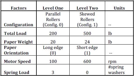
Table 1: DOE Factors and Levels
Hardware Used For Testing:
Four load cells were used, one under each of the load bolts. These cells were used to ensure an even distribution of force across the loading points, as well as monitor any changes in the force as tests occur. Strain gauge based load washers with a rae of 0 to 500 lbs were selected to monitor these forces.
A torque sensor, located between the drive shaft and the motor, see Figure 4 below, was used to monitor the torque required to drive the fuser system with and without paper passing through. A strain gauge torque sensor with a range of 0 to 100 ft-lbs was selected for this purpose.
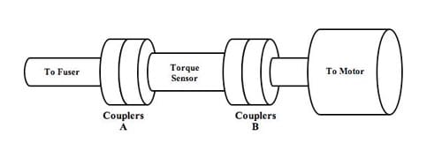
Figure 4: Coupler Schematic
The load cells and torque sensor were connected to a Siglab DAQ system, provided by Xerox. The Siglab program was used to observe and record collected data.
Pressure sensitive film was used to indicate the actual pressure distribution across the nip. Pressurex® Nip Film MS with a range of type of paper is used for this purpose. The pressure film is further discussed in the following section.
5. Results and Discussion
Description of Final Design:
The final fuser design, seen in Figure 3, is composed of four rollers, two “top” end plates, two “bottom” end plates, and four bolts, along with various bearings and support structures. When the bolts are tightened, the top and bottom end plates are drawn together, thus drawing the top two rollers down into contact with the middle roller. The pressure needed to fuse the toner to the paper generated along the nip between the two paper-contacting roller (the middle and bottom rollers).
The final product design attempts to address a number of deficiencies in previous designs. Because the force along the middle roller is applied across its whole length, a much smaller bending moment is generated, thereby lessening the deflection of the rollers in contact with the paper.
Another configuration of the product includes a degree of skew in the top two rollers; when the top two rollers are not parallel with the middle roller, they generate a pressure distribution that is highest in the center and tapers off towards the ends. In general, the greatest deflection of a paper contacting roller, and therefore the lowest generated pressure at the nip, occurs in the center of the length. The skewed roller design applies a greater force in the center of middle roller to compensate for the greater deflection.
In order to achieve the 0.5o skewed roller design, simple trigonometry was used to determine new locations on the top end plates for the top rollers. Self-aligning bearings were used to accommodate the skew of the rollers.
The system was driven with an Electro-Craft E-652-M motor with a 6:1 gearbox via the bottom oller with a coupler system set up as seen in Figure 3.
Test Response Choices:
A number of test responses were used to determine the success of the testing: running torque, maximum torque, minimum and maximum pressure (from pressure sensitive film), the change in paper thickness, paper damage ratio (total length of crease + 2*(total length of rip)), and the average change in the load applied.
The running and maximum torque measurements were chosen as indicators of the power co
nsumption needed to run the fuser. Because the end goal of this technology is a low power fuser, this metric is particularly important.
The pressure film was used to evaluate the uniformity of pressure at the nip. The high and low pressures help measure the pressure distribution; the closer the high and low pressures the more uniform the distribution. The use of the film was justified before the DOE began by comparing the film pressure distribution to the fusing pattern of an un-fused image run through the system. It was found that the pressure distribution of the film aligned well with the fusing of the toner to the paper (i.e. areas of high pressure indicated by the film occurred at locations where the toner successfully fused).
One concern with pressure fusing is that the high pressure deforms the paper past an acceptable level. The nominal paper thickness (average of 3 sheets for each paper weight) as compared to the thickness of each sheet after each test.
The paper damage ratio was also chosen to quantify the paper damage. The ratio takes both the number and length of both paper creases and paper cuts. Both of these failure modes have been observed with high-pressure fusing and skewed rollers, so the paper damage ratio is useful when comparing the current designs to previous pressure fusers.
When a sheet of paper passes through a fuser the rollers are forced apart, producing more load on the bolts and load cells. The change in load was used to help compare the two paper types and the effects of higher loads on the paper.
Test Results:
The DOE provided a number of interesting results. The data from the DOE was put into interaction plots in order to attain any relationships between the different factors. Although the information for the other responses was recorded, the pressure and the torque responses most affect the projects ability to meet the customer requirements. Therefore only these two responses are discussed in depth in this paper.
The following figures are amount the most significant results in terms of the maximum registered pressure:
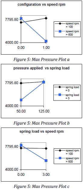
Figure 5: Max Pressure Plot a, b and c
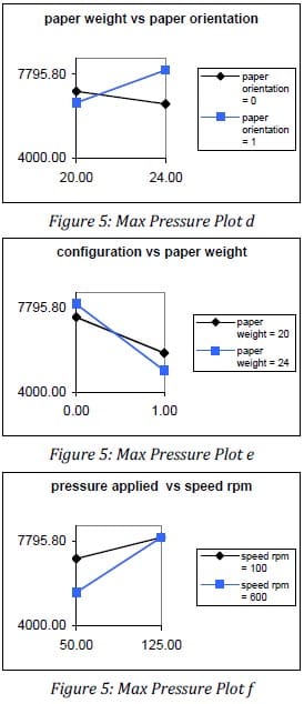
Figure 5: Max Pressure Plot d, e and f
Figures 5a through f each show relationships between the different factors and how they affect the maximum pressure observed in the pressure sensitive film. Figure (5a) shows that at higher speeds the skewed roller configuration results in significantly lower pressures than does either configuration at low speeds or the parallel roller configuration at high speeds. Figure (5b) shows that the pressure registered by the pressure film remains constant when there is no compliance in the system no matter what the applied load is, but there is a significant increase in the registered pressure when there is compliance. Similarly, figure (5c) shows that when there is no compliance the motor speed doesn’t make a significant difference. Figure (5d) shows that the long edge feed results in higher pressure with the 24lb paper, but the opposite is true for 20lb paper. Figure (5f) shows that the speed of the motor makes a larger difference in the registered pressure at lower applied pressures than at higher applied pressures.
It should be noted that the maximum registered pressure along the y-axis of each plot is the maximum value and does not indicate the uniformity of the pressure. The lower registered pressure seen in figure (5e) when the skewed configuration is tested is likely due to the pressure being more uniformly distributed across the nip. The same total pressure is achieved, but the maximum registered pressure is lower because the pressure is spread across the whole nip.
Another effect of greater applied pressure that is not recorded in the DOE is the overall uniformity of pressure, as this was difficult to quantify. It was noted that the greatest uniformity was seen with the skewed configuration at low applied pressures. This observation makes logical sense as the skewed rollers suppress the deflection of the rollers and the deflection is expected to be lower with a lower load.
The DOE also examined the affects the parameters have on the torque requirements. Figure 6 shows these relationships.
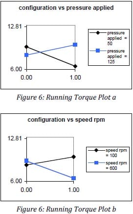
Figure 6: Running Torque Plot a and b
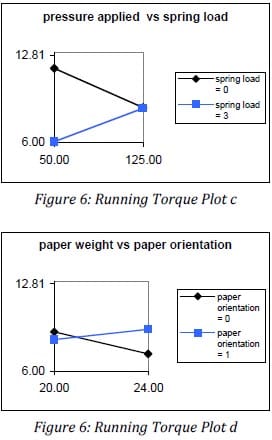
Figure 6: Running Torque Plot c and d
Figure (6a) shows that less torque is required to power the fuser under lower applied load with the parallel configuration than with the skewed configuration, but the opposite is true with the higher applied load.
Figure (6b) shows that the required torque is slightly higher at high speeds than low speeds with the parallel configuration. With the skewed configuration, however, the slower speed rqures a great deal more torque than the fast speed.
Figure (6c) shows that compliance of the system makes a large difference with lower applied pressure – the compliant system requires almost half the torque, whereas the compliance doesn’t make a big difference with a high applied pressure.
Figure (6d) shows that paper orientation makes a larger difference to the required torque when 24lb paper is used than when 20lb paper is used.
One immediately apparent result from the testing is the presence of an oscillation in the data, seen in Figure 7. Possible causes for the oscillations are motor vibrations, especially as the motor was mounted to the same plate as the fusing system, or roller irregularities.
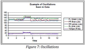
Figure 7: Oscillations
6. Conclusions
Recommendations for Future Designs:
There are many ways in which this work can and should be extended and further explored. The most unique features of this particular design, the application of the load through two skewed rollers, could only be briefly tested due to time considerations. Ideally, the effects of a greater degree of skew should be examined.
Another parameter that could not be tested due to time is a “single hump” vs. a “double hump” design. Both of these configurations are skewed designs, however, with the single hump design, the skewed rollers are aligned in such a way that there is only one strong concentration of pressure in the middle of the paper-contacting roller. The double hump design requires that the rollers be aligned so that each roller provides an offset pressure concentrations from the center of the paper-contacting roller, providing two concentrations of pressure. The skewed roller configuration in this work utilized the single hump configuration.
The skewed roller design, both single and double hump, should also be tested with various degrees of skew. It is believed that the higher the degree of skew, the larger the pressure concentration in the center of the paper contacting roller. There is bound to be an optimal combination of skew configuration and skew degree, however, the previously mentioned difficulties in analyzing any type of skewed roller system makes experimental exploration the most feasible method of determining this optimal design.
It is recommended that the rollers for next generation of this design be ground and polished. While the rollers were ordered with a tolerance of 0.5 thousandth of an inch in diameter, irregularities in the diameter acr
oss the length of the roller can be observed by the irregular gapping visible between the rollers. The importance of precise machining became abundantly clear throughout this process, and the surface finish of the rollers is no exception. Smooth and clean rollers are very important for future works.
As mentioned in the results, an oscillation in the load cells was observed throughout testing. The oscillation in the load will affect the pressure uniformity and, most likely, the lifespan of the rollers. It is possible that this oscillation is dependant on irregularities in the roller. The source of the oscillation should be found and removed as far as is possible.
For future work it is also recommended that a different material be chosen for the end plates. While stainless steel worked well in the actual testing part of this project, it is extremely time consuming to manufacture. In order to explore all the recommended configurations it would be best to select a more machinable material without compmising the structural integrit of the fuser.
Recommendations for Future Testing:
Future testing should include a more accurate measure of fusing success than pressure uniformity as indicated by the pressure sensitive paper. It was found that the maximum and minimum pressure metric used through this DOE was not ideal because most of the tests resulted in similar maximum pressures. The differences in the pressure uniformity were not taken into account with the current pressure metric. A recommendation for a more accurate metric is to produce a full page of un-fused half tone paper for each test. After the image is passed through the fuser a simple smudge test could be performed to ascertain the actual, practical pressure uniformity.
It was found through testing that concentricity of the load cells to the bolts is extremely important to the accuracy of the load readings. It is therefore recommended that a procedure or fixture is put in place to ensure that the load cells are consistently and precisely aligned relative to the bolts.
Another challenge of the testing was the torque sensor wires; whenever the motor ran, the wires would get wrapped around the torque sensor, slowing down the testing and becoming potentially damaged. A more efficient method of measuring torque is recommend potentially through the use of a rotary contact for the existing load cell, or a motr with an integrated torque sensor.
Recommendations for Future Testing:
Although more testing is needed to fully quantify the performance of each of the fuser configurations, these first generation four roller fusers can be considered successful. An informal (non-DOE) test for each configuration: an un-fused image was passed through each configuration long edge first at a low applied pressure (about 50 lb). The parallel configuration fused the images towards the outsides of the paper, but did not fuse the middle of the image. The skewed configuration, however, fused the whole image with only mild smudging.
Perhaps more than the rest of the results, these informal tests show not only that this particular design works, but also that the skewed design makes a large difference in the outcome of the fused images. While the hardware produced is not ready to be mass-produced, the concept has been proven to be worthy of further study.
References
- “Glossary of Printing & Graphic Terms.” Printing Industry. 1997-2009. 1 May 2009 .
- Thompson, David, and Dinesh Tyagi. “Fusing Technologies and Toner Material Relationships.” 4th International Conference on Digital Printing , Technologies. Pittsburgh, PA. 8 Sept. 2008.
- Calabrese, Richard A. Cold Pressure Fusing Apparatus. Pitney Bowes Inc, assignee. Patent 381,814. 1981.
- Monkelbaan, Edwin R. Three-roll Cold Pressure Fuse For Fixing Toner Images to Copy Substrates Including an Overskewed Roll. Xerox Corporation, assignee. Patent 387,061. 1982.


