H. D. Espinosa, A. J. Patanella, M. Fischer
Abstract
Understanding high speed machining processes requires knowledge of the dynamic friction response at the tool-workpiece interface, the high strain rate response of the workpiece material and its fracture mechanisms. In this paper, a novel experimental technique, consisting in the independent application of an axial static load and a dynamic torque, is used to investigate time resolved dynamic friction. Shear stress wave propagation along an input bar, pressing statically against an output bar, is analyzed. The quasi-static and kinetic friction coefficients of Ti-6Al-4V sliding against 1080 Steel, Al 6061-T6 sliding against 1080 Steel, and Al 6061-T6 sliding against Al 7075-T6, with various surface characteristics, are investigated. Sliding velocities up to 6.9 m/s are achieved. Surface roughness is varied to understand its role on the frictional response of the sliding interfaces. The dependence of friction coefficient on material strain-rate sensitivity is also assessed. Measured friction coefficients compared well with values reported in the literature using other experimental techniques. The experimental methodology discussed in this article provides a robust method for direct measurement of the quasi-static and dynamic friction coefficients representative of high-speed machining, metal-forming and ballistic penetration processes. [S0742-4787(00)01304-7]
1 Introduction
Recently, attention has been focused on the mechanics of high speed machining as a means for increasing manufacturing productivity through reduction of machining time. Some substantial savings have been achieved in the area of machining traditional materials. However, there are still limitations in the tool life that have prevented advances in the machining of materials having high strength or hardness such as titanium alloys, high strength steels, nickel alloys, and ceramics.
Friction is a very important factor in high-speed machining and ballistic penetration processes. In fact, friction and wear on the rake face as well as on the clearance face play very critical roles in the performance and life of a cutting tool, Komanduri et al. [1]. Other mechanisms such as shear-banding and chip formation need an in-depth understanding if the machining process is to be improved, Komanduri et al. [2]. Similarly, friction and material instabilities are extremely important in modeling ballistic penetration, see for instance Zukas [3], Meyers [4], Camacho and Ortiz [5], and Espinosa et al. [6,7].
Another application related to the frictional behavior of materials is in their usage as coatings in components of rotary or linear motion devices. Most devices work lubricated making a study of dry friction apparently unnecessary. However, this is the case only when the machine or device reaches its operational steady state. During the transient period, in which the devices are cold, in other words without enough lubrication and sometimes without any, solid to solid friction plays a major role. In addition, devices that due to their complexity or specific use cannot employ oil or another type of lubrication have to be considered, e.g., inertia wheels for steering satellites. In these advanced materials applications, an in-depth understanding of their frictional response is highly needed.
A wide variety of experiments are required to fully characterize the friction phenomenon. In such experiments, conditions of pressure, velocities, surface characteristics, and temperature, present in applications of interest, need to be achieved. A simple geometry, from which local interface traction and sliding velocity can be easily measured, must be employed. In this way, mathematical models of frictional behavior of interfaces can be used to describe the friction phenomenon. In turn, these models can be incorporated in computational simulations to gain insight into the main features associated to these processes.
Nowadays there are several experimental techniques available for the study of dynamic friction. They are basically divided in the following groups:
• Pressure-shear plate impact frictional experiments, Prakash and Clifton [8], Prakash [9] and Espinosa et al. [10], were employed to investigate time-resolved friction. The configuration offers the simplicity of allowing the interpretation of the experimental results by using the framework of elastic plane wave analysis. These experiments can simulate local conditions of pressure and slipping velocities occurring in high speed machining applications.
• Modified Split-Hopkinson bar method, Ogawa [11]. This technique consists of applying a dynamic axial force to a rotating bar/specimen system. The method can be used to investigate transient response under dynamic loading. To understand the dynamic contact of two bodies with initial velocities, the impact load must be applied in the normal and tangential direction simultaneously and the corresponding reactions must be evaluated independently. This methodology is in the early stages of development. Typical sliding velocities investigated with this apparatus are on the order of 1–5 m/s. The Kolsky bar apparatus was also used by Feng and Ramesh [12], in the study of lubricants.
• Pin-on-disk tests, designed for low-velocity friction experiments, where the kinetic friction is evaluated only in the steady state condition, see ASM Handbook [13–15]. This is very helpful in understanding the mechanisms involving degradation of material surfaces in contact for a long period of time.
• Various other techniques, ranging from quasi-static conditions to very low sliding velocities, primarily used for studying quasi-static frictional behavior; see, for instance, Anand and Tong [16], Anand [17].
In this article, we start by presenting the design of a modified Kolsky bar apparatus, suitable for the investigation of dynamic friction at sliding velocities between 1 and 7 m/s. The experimental methodology together with a summary of formulas, used to interpret the experimental data, are presented. A discussion of the time evolution of interfacial friction, in several material pairs, is given. The material pairs include the following, Al 6061-T6, Ti 6Al-4V, 1080 Steel, and 4340 Steel.
2 Dynamic Friction Experiments
2.1 The Stored-Energy Kolsky Bar
The torsional Kolsky bar, also called split-Hopkinson torsional bar, is a reliable apparatus for testing materials at strain rates from 10² to 104 s-1. In 1949, Kolsky used a modified pressure bar to test thin, wafer-like specimens at high strain rates, see also Kolsky [18]. The loading was accomplished by propagating a compressive wave down one of the bars toward the spe
cimen. Measurements of the waves in the elastic bars were made on each side of the specimen. Kolsky showed that the portion of the incident loading wave that is transmitted through the specimen provides a measure of the axial stress in the specimen, while the magnitude of the wave that is reflected is proportional to its strain rate.
The same general analysis applies to torsional loading with angular velocity and shear stress replacing axial velocity and axial stress. By combining outputs from the strain gages on either side of the specimen and by integration of the strain rate versus time, a complete record of the stress-strain curve can be obtained easily and accurately, Duffy et al. [19].
Several investigators contributed to the development of the torsional Kolsky bar. Duffy et al. [19], originally used explosive loading to initiate the loading pulse. This method has the advantage of producing a shorter pulse rise time, whereas a stored-torque loading system provides potentially a more progressive dynamic loading, Gilat and Pao [20]. This last configuration is the one chosen for the design of our dynamic friction experimental technique.
A stored-energy Kolsky bar, shown schematically in Fig. 1 and after construction in Fig. 2, was designed and built to investigate dynamic friction and compression-shear material behavior with specimen recovery. It is composed of two 25.4 mm (1 in.) 7075-T6 aluminum alloy bars. The so-called incident or input bar is 2.3 m (90.5 in.) long and the so-called transmission or output bar is 1.9 m (75 in.) long. Each bar is supported along its length and aligned properly. It is supported by a series of re-circulating ball fixed-alignment bearing (INA KBZI6PP) minimizing the friction resistance on the supports and allowing the bar to rotate and translate freely in both directions. The compression/tension and shear loading pulses are produced by the sudden release of the stored elastic energy. This requires both torsional and compression/tension actuators. The axial part of the elastic energy is produced by means of a hydraulic double acting actuator (Enerpac RD 166) which applies a compressive or tensile load at one end of the incident bar. Its capacity is 35 kip (150 kN). The torsional part of the elastic energy is achieved by means of a hydraulic rotary actuator (Flo-Tork 15000-180-AICB-ST-MS2- RKH-N) located along the incident bar. It is connected to the bar by a 3/89 steel key. Its capacity is 1700 N•m (15,000 Ib•in.). The sudden release of the stored energy is achieved using a clamp positioned between the rotary actuator and the specimen. The design of the clamp is crucial for good results. The clamp must be able to hold the desired torque and compression/tension force, without slippage, and release the stored energy rapidly enough to produce a sharp-fronted stress pulse traveling towards the specimen.
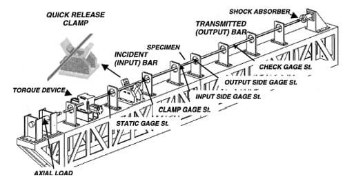
Fig. 1 Drawing of the stored-torque torsional Kolsky Bar Apparatus. Each gauge station has
full strain gage bridge arrangement to measure torsional loads (with an alignment of 45 deg respect
to the longitudinal axis of the bar) and to measure axial load (aligned parallel to the longitudinal
axis of the bar), except for the bending station (half bridge) which monitors the presence of
any spurious bending wave transmitted through the specimen.
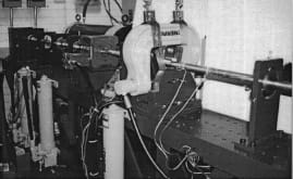
Fig. 2 Photograph of the stored-energy Kolsky bar apparatus
In the case of friction experiments, the axial load can be applied before gripping the clamp, i.e., the friction phenomenon is studied under quasi-static pressure conditions and a certain amount of angular velocity, or it can be applied dynamically. In the first case, upon release of the clamp, a torsional pulse, with constant amplitude equal to one half of the stored torque, propagates down the bar towards the specimen. Simultaneously, an unloading pulse of equal magnitude propagates from the clamp towards the rotary and axial actuators. The torsional mechanical impedance of the rotary actuator is sufficiently large, that after reflection, the unloading wave reduces the torque in the incident bar to zero as it propagates back along the bar. This is proven in the characterization and calibration process of the bar, see Patanella [21]. The Lagrangian X-t diagram of the quasi-static axial load and shear wave propagation is shown in Fig. 3(a). In the second case, compressive and torsional waves are produced simultaneously. The longitudinal and torsional elastic wave fronts, along the bar, are shown in Fig. 3(b). Upon release of the clamp, two waves, longitudinal and shear, are propagated towards the specimen and towards the hydraulic actuators. The length of the bars and the actuators positions are selected such that the incident pulse duration can be transferred to the transmission bar before momentum trapping caused by the arrival of an unloading wave, to the contact surface, from the right end of the transmission bar. This trapping concept is identical to one used by Clifton and co-workers in the study of plate impact with specimen recovery, see Kumar and Clifton [22]. It should be noted that since the specimen consists of two surfaces in contact, separation of the output bar leaves the incident bar free to translate and rotate due to the effect of the waves trapped in the incident bar.
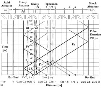
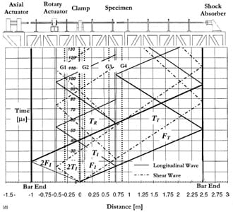
Fig. 3 (a) Lagrangian X-t diagram of friction experiment with quasi-static axial load and dynamic
torque; (b) Lagrangian X-t diagram of friction experiment with specimen subjected
to a single compression-shear pulse.
The choice of applying the axial load, quasi-statically or dynamically, is based on the fact that there is a trade off which needs to be kept in mind. In fact, if the axial load is applied quasistatically, high sliding velocities can be achieved by maximizing the stored torque. If an axial load is stored by the clamp, the magnitude of the storable torque decreases accordingly to avoid sliding at the clamp pads. It should be pointed out here that in the case of applying the axial load quasi-statically, the reverberating shear waves, after the main pulse, are attenuated and do not n
ecessarily produce further sliding. Hence, post-examination of the sliding surfaces can be made to characterize the friction mechanisms.
In our view, the apparatus here described is conceptually simpler than the one discussed by Ogawa [11], and can be easily obtained through modification of the traditional Kolsky bar available at many research laboratories. Moreover, the apparatus can also be used to study shear banding and dynamic failure of advanced materials, with specimen recovery, when both compressive and shear pulses are applied.
2.2 Formulas for Dynamic Friction Coefficient Calculations
We start this section by re-examining the X-t Lagrangian diagram of the torsion bar as shown in Fig. 3(a). The duration of the loading pulse is the time required for the pulse to travel twice the distance along the bar between the clamp and the torsional actuator. The pulse duration can be varied by moving the clamp and torsional actuator positions along the incident bar. The allowable relative separation between these devices is about 1 m (40 in.). In that case, the pulse duration can be adjusted up to 650 μs. The configuration used in our tests is set to a 290 μs pulse.
As the pulse travels down the bar, it is detected by two strain gage stations on the incident bar and another one on the transmitted bar. Each station consists in a full bridge arrangement of four strain-gages of 350 Ω (MM EA-13-250BF-350). The four strain gauges are located at 45 deg respect to the longitudinal axis of the bar separated 90 deg in the radial direction one from the other, for measuring torsional waves. Four strain-gages, located parallel to the longitudinal axis and separated 90 deg in the radial direction, are used for measuring the longitudinal waves. In each case, the specific measurement is independent of any other potential loading on the bar, i.e., the effect of loads different to a torque (in the torsional gage station) or compression/tension (in the axial gage station). An extra station is added between the clamp and the torque device to measure the stored static torque.
The specimen geometry is shown in Fig. 4. It is composed of two disks one of which has a hollowed end. The specimen is designed such that an uniform traction is obtained in the annular contact surface. Furthermore, the specimen inner and outer diameters are chosen such that an approximately uniform sliding velocity is obtained.
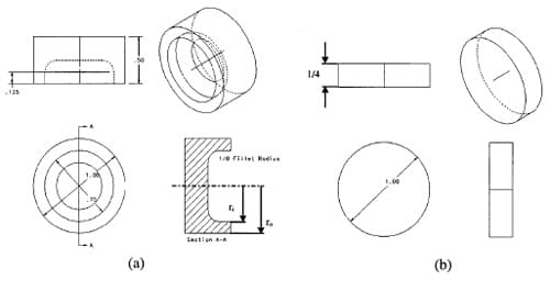
Fig. 4 Friction specimen: (a) disk attached to the incident bar; (b) disk attached to the transmitted bar
Based on the above description of pre-compression, elastic torsional waves and measurement stations, we can infer that the shear frictional stress in the contact area of the sample is given by
where TT is the transmitted torque, measured at gauge station G4, Jps is the contact area polar moment of inertia and r is the centerline radius.
The angular velocities •θi and •θo, of the input and output bars, represent the angular velocities at the contact surfaces. Using the method of characteristics, see Espinosa et al. [23], they can be expressed in terms of the incident, reflected and transmitted torques by
where Jp is the polar moment of inertia of the bar, Cs is the torsional wave speed of the bar, p is the mass density of the bar, TR the reflected torque, and TI the incident torque. Because a change in polar moment of inertia takes place at the sample location, the above equations strictly hold when a steady state condition is achieved at the sliding interface. However, elastic wave analysis shows that such effect is very small and only for a few microseconds. Since the pulse duration is of a few hundred microseconds, for all practical purposes, the change in polar moment of inertia can be neglected and does not affect the interpretation of the results. This was experimentally confirmed. The reflected pulse starts with the onset of sliding rather than with the arrival of the torsional pulse to the specimen interface, see discussion of experimental results and plot of raw signals. Additionally, we have conducted an experiment in which the annular cross-section was glued to the transmission bar. The purpose of such experiment was to identify the sole effect of the change in polar moment of inertia. In confirmation with the theoretical analysis, the amplitude of the reflected pulse was only 3 percent the amplitude of the incident pulse.
The average sliding velocity over the contact area is given by
where ro and ri are the outer and inner radius of the specimen contact area, respectively, and r is the radius. See Fig. 5(a).
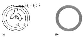
Fig. 5 (a) Schematic of radial velocity distribution; (b) pressure distribution, along the
contact area, measured by means of a pressure sensitive film
Solving the integrals a relation between the average sliding velocity and the torques is obtained, viz.,
Furthermore, if the transmitted pulse is expressed as the difference between the incident and the reflected pulses (TT=TI+(-TR)) the average sliding velocity becomes
The validity of the expression (TT=TI+(-TR)) was verified experimentally by independently measuring each torque.
The relative average displacement between the surfaces in contact can be determined from Eq. (2.6) upon integration as
where t is the duration of the loading pulse.
The normal stress in the contact area is determined by the static pressure applied on the specimen by means of the axial hydraulic actuator. The axial load (NI) is measured by a strain gage station located before the clamp. The macroscopic normal stress is directly computed as
where Ac is the contact area.
The shear stress is computed by means of elastic wave propagation theory, as it is t
he case in shear dynamic strength studies. However, in this case the thin wall theory cannot be used due to the thickness of the contact wall. For this case, replacing the value for the polar moment of inertia of the sample in Eq. 2.1 we obtain,
Then the shear stress averaged over the contact area can be expressed by

At this point all the variables needed to compute the friction coefficient μ, are defined. This coefficient is given by the ratio between shear and normal traction, viz.,
The above formulas provide a direct measurement of the quasistatic and kinetic frictional properties by using load (strain) histories detected at the output and input bars.
3 Experimental Procedure
A static axial load is applied before the clamp is actuated to hold the torsional load. In this way, the surfaces of the pair of materials to be tested are pre-stressed with a known pressure. It is very important that the surfaces in contact constitute an annulus with small thickness, where the torsional stress profile can be assumed to be almost constant. In this way, an almost constant profile of relative sliding velocity along the radial direction can be achieved. For this reason, the specimen geometry, as the one shown in Fig. 4, was chosen.
Before the test, each sample was grounded and lapped to ensure the flatness and parallelism of their surfaces. A Lapmaster 24 lapping machine, from Crane Co., and silicon carbide powder of 12.5 μm was employed. The specimens were cleaned using MEK and acetone in an ultrasonic bath for 30 minutes. After that, the samples were marked and labeled carefully. Marking was performed to allow the study of surface changes, in the area surrounding the mark, after the experiment. The objective was to qualify the friction mechanisms in the pair of materials tested.
To analyze the surface properties, an Atomic Force Microscope (AFM) from Digital Instruments model Dimension 3100A, was used. On each tested sample, an area of 50 μm by 50mm about 50 μm from the mark was scanned. The surface profile, a three-dimensional micrograph and the average roughness in that area were taken from each scan, in each sample. Figure 6 provides a sample of the scanned data and parameters taken from the aluminum samples. The most important values taken from the roughness analysis, as shown in Fig. 6, are the Rms (Rq) and the Ra. The Rms, root mean square value, is defined as the square root of the deviations and represents the standard deviation of the asperity height distribution, Larsen-Basse [15]. The Ra, average roughness, is the mean vertical height deviation of the asperities measured from the centerline of the surface between peaks and valleys, Larsen-Basse [15]. In the section analysis, the most important features are the profile of the section and the maximum distance between valleys and peaks. All these parameters are measured again, after the experiment, to examine the amount of roughness change and to infer the friction mechanisms present in the test.
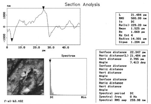
Fig. 6 Sample of roughness analysis with the atomic force microscope DI 3100A
Before clamping the incident bar, it is necessary to check that the pressure along the contact area is uniform. This very important variable in the experiment needs to be verified using a nonintrusive method to avoid altering the surface characteristics and also to avoid adding contaminant elements to the surfaces in contact. The simplest method that meets all these requirements is the use of pressure sensitivity films. These films have a layer of micro-capsules which are broken under pressure. A color-forming material is released, reacting with the color-developing layer to generate a graded color scale. A Fuji Prescale Pressure Measurement Film from Fuji Photo Film Co. is used. The pressure in the contact area is usually greater than 10 MPa so a medium pressure scale film is used ranging from 10 MPa to 50 MPa. A sample pattern obtained from an experiment is shown in Fig. 5(b). The shaded ring represents the contact area and the grade of the shade represents the pressure in that interface. The pattern shown is quite uniform. The same uniformity is kept in all the experiments. If the pressure pattern is non-uniform, the samples have to be positioned again or further lapped until a uniform pattern is achieved.
After the specimen is glued, the pressure distribution on the contact area checked, and the surfaces cleaned, the test is conducted. The cleaning is performed using MEK and acetone, to eliminate any oil or grease resulting from the contact pressure measurement, and methanol to eliminate any residues left by the acetone.
The contact pressure is set to the desired value by means of the axial load actuator. Then, the clamp is closed and the torque stored to achieve the desired sliding speed. This process takes between 1 to 2 minutes. Hence, the materials are in contact for this period of time prior to the friction measurement. After releasing the stored torsional energy, by breaking the clamp pin, the signals are recorded in an oscilloscope using the incident pulse signal raise ramp to trigger the scope. A typical recording is shown in Fig. 7. Several pulse features are worth noting. First, the rise time of the transmitted pulse is about 50–90 nanoseconds. Pulse rise times of this order are ideal to capture the onset of sliding, as will be explained later. Second, absence of an axial pulse, upon release of the clamp, is evident from the constant measurement at gauge station 1b.
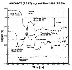
Fig. 7 Recorded data at four gauge stations
4 Experimental Results and Discussion
Several experiments were conducted to study particularly the frictional behavior of different pairs of materials such as
• Aluminum 6061-T6 (RB 97)—Steel SAE 1018 (RB 89)
• Titanium Ti 6Al 4V (RC 33)—Steel SAE 1018 (RB 89)
• Aluminum 6061-T6 (rough) (RB 97)—Aluminum 7075-T6 (RB 61) (mirror polished)
• Aluminum 6061-T6 (rough) (RB 97)—Aluminum 7075-T6 (rough) (RB 61)
In each set of experiments the average sliding velocity was measured to be in the order of 3 to 5 m/s. Based on the duration of the loading pulse, about 290 μs, the amount of slip between the surfaces is about 1 to 2 millimeters. Geometrical parameters and surface characteristics for each sample are reported in Appendix A.
A typical experimental result is shown in Fig. 8. A ten moving point average was added to the data processing procedure to reduce the oscillations produced by data noise. Note that no amplification or filtering is done to the original signal. This curve is obtained by processing the raw data shown in Fig. 7 using the theoretical analysis presented in Section 2.2. The formulas given in Section 2.2 were programmed using the Excel ’97 software from the Microsoft Corporation in order to make the data reduction process automatic.
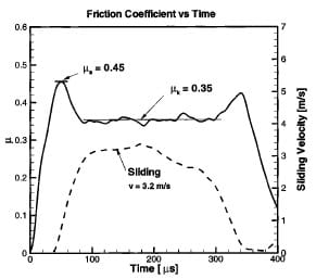
Fig. 8 Time evolution of friction coefficient and sliding velocity
A couple of features can be pointed out from the frictional response shown in Fig. 8. Two peaks in the friction coefficient are found. They are marking the beginning and the end of the pulse where the sliding velocity is raising from zero to sustain a constant value and then decaying to reach the rest condition again. Due to this behavior, the first peak represents the quasi-static coefficient of friction (μs) and then, after a transient time, the sliding velocity remains approximately constant for 100 microseconds providing a measure of the kinetic friction coefficient (μk). At the end of the pulse, the velocity is reduced and the coefficient of friction raises again towards a value corresponding to μs . This second value of μs is expected to be lower than the first one due to the changes on the sliding interfaces by the previous loading. In some experiments no second peak is found. Probably because the amount of plasticity generated on the asperities of each surface reduces the surface roughness in such amount that the quasi-static friction coefficient is drastically reduced. This response can be understood by studying the sliding process, Madakson [24]. When the tangential load is applied, a first elastic deformation of the asperities and the substrate takes place. It continues until the shear strength of the junctions is reached. Shearing of the junctions now takes place and the coefficient falls off as the strong junctions, which were formed during quasi-static loading (initial pressure), become replaced by weaker ones. The influence of the strong junctions persists over a distance that is simply related to the average junction size. That behavior is strongly affected by the strain rate sensitivity of the material under study. Some models were developed in order to relate all the material properties to the friction phenomena. However, many of them fail under certain conditions. An example is the modeling of plastic deformation of the surface asperities. The link between the time dependent plasticity and surface friction is difficult to achieve due to the large number of variables involved in the friction phenomena, Madakson [24] and Martins et al. [25]. Some models have successfully incorporated material strain rate sensitivity on the prediction of the friction coefficient, as described by Brechet and Estrin [26]. These models may provide valuable tools to further understand the experimental observations here discussed. The key feature is that the measurement shown in Fig. 8 provides insight into the evolution of friction.
The actual area of contact between two solids in friction is only a small fraction of the nominal contact area, Ludema [27], as represented in Fig. 9. The asperities in contact, forming a junction, deform elastically until the shear stress supported by each junction reaches the value of the materials yield stress. Then the force necessary for sliding is determined by the stress needed to shear the junctions. In this context, the quasi-static friction coefficient is time independent. However, early experiments, Rabinowicz [28], showed that the quasi-static coefficient is time dependent. Moreover, it was suggested that this dependence is the very cause of the sliding velocity dependence of the dynamic friction coefficient. The average time for shearing of an asperity is inversely proportional to the imposed sliding velocity, Blau [13]. This aging effect, and hence the strength of the junctions and the attainment of a given friction coefficient value diminish with growing velocity. In the case of dynamic friction, in which the sliding velocities reach several m/s, material rate dependence and thermal softening effects play a dominant role.
![Fig. 9 Schematic of two surfaces in quasi-static contact sliding one against each other, Ludema [27] Fig. 9 Schematic of two surfaces in quasi-static contact sliding one against each other, Ludema [27]](https://www.sensorprod.com/wp-content/uploads/2023/08/image09-6.jpg)
Fig. 9 Schematic of two surfaces in quasi-static contact sliding
one against each other, Ludema [27]
The effect of sliding distance on friction depends on the nature of the initial deformation of the rubbing surfaces which is governed by the surface finish (roughness), normal load, sliding velocity, material properties and environmental conditions, Larsen- Basse [15]. The first stage of friction, in which a quasi-static phenomenon is encountered, can be easily seen in the experimental data shown in Fig. 10. The effect of the break down of asperities can be observed in this plot. They basically correlate with sliding distance S’. This effect is significant when the elastic part of the friction phenomena is taking place. After the plastic process starts, the surface is deformed enough to reduce the friction coefficient to the kinetic value.
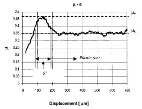
Fig. 10 Friction coefficient as a function of sliding distance
The extent of plasticity found on the contact surface, on both sides of the contact interface, is a function of the mechanical properties of the surfaces in contact, such as surface hardness and shear strength of each material. Surface hardness is reported in Table 1. This feature can be observed on the surface analysis of tested samples, in which the harder material, i.e., the one with the higher flow stress, presents significantly less plastic deformation than the softer material. The plastic deformation is found as scratches left by the asperities of the harder material in the contact area, see Fig. 11. Grooves generated due to the plowing of asperities and blunting of asperities peaks are also observed. This behavior is illustrated in Figs. 12–14, where the contact area of each pair of tested materials is shown with their characteristics before and after the experiment.
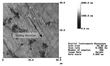
Fig. 11 AFM micrograph of the contact area on A16061-T6 after sliding on Steel 1080 at 3.1 m/s.
Surface height is given by the bar scale in the range 0–3000 nanometers.
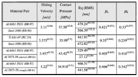
Table 1 Summary of experimental results
A careful examination of the AFM data presented in Figs. 12, 13, and 14 reveals how material properties change the frictional behavior of the interfaces, and how friction can alter the surfaces in contact. For example, in the case of Fig. 12, the Al 6061-T6 surface undergoes plastic deformation leading to a reduction in overall roughness of about 28 percent its original value. The 1080 Steel seems to have more roughness reduction, and it also shows incrustations left by the Al 6061-T6 in-between asperities. This leads to an overall roughness reduction of about 70 percent. This significant reduction in roughness is due to the plowing of asperities in the aluminum, which coats the steel, mostly at surface valleys. The Al 6061-T6 flow stress is smaller than the 1080 Steel flow stress, and, hence, its asperities are easi
ly plowed away from the contact area while sliding occurs. In the case of the Ti 6Al 4V-1080 Steel pair (Fig. 13), the variations on surface properties in the titanium side are not as significant as the ones found in the 1080 Steel. In the titanium sample, asperities boundaries almost uncontaminated are seen. The peaks are flattened with a significant change in asperity distribution. This blunting effect can be attributed to the normal pressure applied in the contact area before sliding takes place. The average pressure, in the contact area, is of the order of 30 MPa. However, at the peaks of the asperities this value is increased by the stress concentration introduced by the sharp ends reaching values in excess of the material flow stress. On the other hand, looking at the steel side, almost all the asperities were sheared off leaving a smoother surface. This was expected because the yield stress of the tested 1080 steel is almost three times smaller than the one found for Ti 6Al 4V. Finally, in the last example, Fig. 14, the amount of change found in the mirror-polished Al 7075-T6 surface is large when compared with its original state. There are a large number of scratches generated by the asperities of the other sliding surface on the mirrorpolished surface, which roughness is more than 10 times the original value. This particular case will be discussed in more detail later in this section because of the observed peculiar time evolution of the friction coefficient.
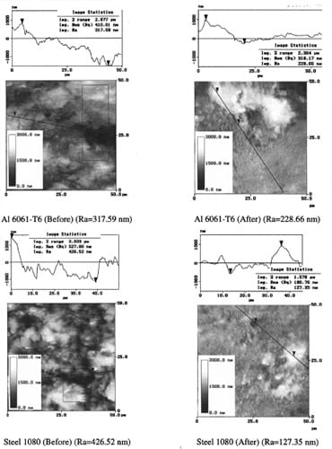
Fig. 12 Surfaces characteristics before and after the experiment.
Al 6061-T6 sliding against Steel 1080 at 3.1 m/s. Image statistics performed along black lines.
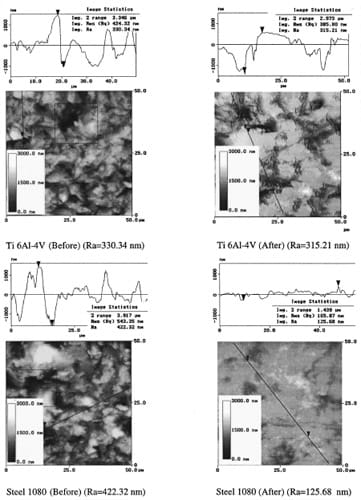
Fig. 13 Surfaces characteristics before and after the experiment.
Ti 6Al-4V sliding against Steel 1080 at 3.75 m/s.
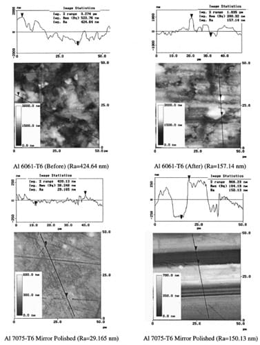
Fig. 14 Surfaces characteristics before and after the experiment.
Al 6061-T6 rough sliding at 3.1 m/s against Al 7075-T6 mirror polished.
A summary of experimental results together with the parameters obtained for each type of experiment is listed in Table 1. The data is presented taking the average value found in every particular set of experiments. The computed standard deviation is given between parentheses. The complete data set for each experiment is reported in Appendix A. The scatter found in the data can be attributed to the many variables involved in the experiment, but after several experiments a clear trend can be drawn for each pair. The deviation falls in the order of 10 percent which is acceptable for engineering applications. Moreover, the quasi-static friction coefficients obtained are in agreement with data reported by different investigators using other test methods.
The measured time evolution of the friction coefficients can be compared to friction coefficients reported in various references, Blau [13], Rabinowicz [28,29]. The friction coefficient between solids under non-zero normal force is a function of several factors whose relative contributions vary on a test-by-test basis making difficult the homogenization of the reported values. The fact that the obtained quasi-static friction coefficients are within the range reported in the literature shows the validity of the procedure here presented. One should be aware of the shortcomings in comparing friction coefficients obtained by various investigators. Values reported by Blau [13], in the ASM handbook suggest a good match with the one found using the Kolsky bar experimental technique. For example, for Al 6061-T6 sliding on steel, Blau reported μs ≈0.48 and a μk≈0.38. In the case of Ti 6Al-4V Blau reported μs≈0.36 and μk≈0.32 and for the Al 6061-T6 sliding against aluminum he reported a μs≈0.42 and μk≈0.34. All these values were found using a test geometry of a flat surface sliding against another flat surface. Madakason [27], reported a μs≈0.52 for Al 7075-T6 sliding on Al 6061-T6 using a pin-on-disk configuration. In conclusion, the values determined using the modified Kolsky bar fall in between the scatter reported in the literature proving the new methodology satisfactory.
One important feature on the time evolution of the friction coefficient was found in the case in which one of the surfaces in contact was mirror polished. In this case, our experiments show that the quasi-static friction coefficient is smaller than or almost equal to the kinetic friction coefficient. This behavior is related to the lack of large asperities in the mirror-polished surface (as shown in Fig. 14). A Ra of the order of 30 nm was measured for the Al 7075-T6 disk. It can be expected that the history of contact points, between surfaces in contact, differs significantly from the case in which both surfaces are rough and have similar values of Ra. An example of such μ-time history is shown in Fig. 15 for the tribo-pair Al 6061-T6/Al 7075-T6. The generation of grooves on the Al 7075-T6 surface can be clearly observed in Fig. 14.
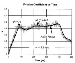
Fig. 15 Friction coefficient versus time for Al6061-T6 sliding at 3.1 m/s
on Al7075-T6 mirror-polished
Figures 16(a) and (b) show optical micrographs of the aluminum surfaces after the tests. Figure 16(a) corresponds to the test in which the Al 7075-T6 is mirror polished and Fig. 16(b) corresponds to the case in which the Al 7075-T6 is rough-finished. In the case of the mirror-polished surface, it can be seen how the rough Al 6061-T6 asperities plowed the polished Al 7075-T6 surface. These imprints are the origins of the scratches generated when the sliding process starts, see Fig. 16(a). The Al 6061-T6 rough surface shows almost no variation in morphology, only a small reduction in roughness can be measured. No deep scratches can be seen in its surface. The same behavior was found in all the samples studied where one of the surfaces was mirror polished. When the same pair of materials is tested with both sides having similar roughness, the value of the quasi-static friction coefficient departs from the kinetic one (μs≈0.466, μk≈0.342 at 3.22 m/s, reported in Table 1). The quasi-static friction coefficient is higher than the one encountered for the c
ase discussed previously (μs≈μk≈0.41 at 3.45 m/s). This change in the friction coefficient takes place because the friction mechanism changes when both surfaces are rough. The interlocking mechanism results in a higher μs. When the shear stress produced by the shear wave, reaches a value close to the material flow stress, the asperities are plowed and sheared reducing the frictional coefficient. This can be seen in the micrograph shown in Fig. 16(b). Here, no new asperities are generated. By contrast, some are eliminated. Both surfaces showed a marked deformation with holes left by imprints and scratches of the same magnitude in both surfaces. This example shows the importance of roughness and plasticity in the friction phenomena and how it can affect the frictional response of a pair of materials in contact.
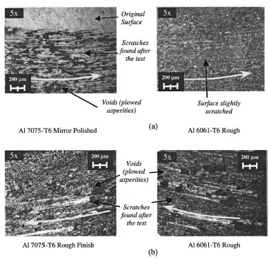
Fig. 16 Friction surfaces for Al6061-T6 sliding against Al7075-T6
mirror-polished and rough-finished
Many parameters can be varied to study the frictional behavior of materials. Various combinations of sliding velocities, pressure, and roughness of the surfaces need to be tested. The parameters, in all the conducted experiments, were kept in a narrow range in order to investigate the repeatability of the measurements and roughness effects. In this way, the measured friction coefficients were compared with values reported in the literature, to validate our experimental approach. In-depth frictional studies in other advanced materials will be reported in future publications.
5 Conclusions
A new testing technique was developed by modifying the Kolsky apparatus. A dynamic shear stress and a static precompression are applied, independently. This leads to a unique capability to investigate the dynamic friction of several types of industrial processes and ballistic penetration. Stress wave propagation of a torque stored in the input bar, traveling through the specimen towards the output bar, was analyzed and experimentally verified. During the verification process, dynamic friction studies of Steel, Aluminum and Titanium alloys were carried out.
The normal and tangential forces were directly and independently recorded by the measurement of the incident, reflected and transmitted pulses in the input and output bars. Thus, giving a direct reading of the sliding speed and friction coefficient. The quasi-static and kinetic friction coefficients for various material pairs were obtained. The kinetic friction coefficient was obtained in a range of sliding velocity up to 7 m/s for different contact pressures. Short sliding distances (1 to 2 mm) permit the study of the surfaces, on the recovered samples, providing insight into the early frictional mechanisms. The velocity dependence of the friction coefficient and its relationship with the strain rate sensitivity of the materials was inferred from the experimental measurements. In the investigation here reported, the contact pressure is applied quasi-statically to be able to maximize the applied torque and hence maximize the sliding velocity. However, as discussed previously, for the recovery of specimens subjected to a single shear pulse, the simultaneous generation of both axial and torsional waves is needed. In this way, microscopy studies performed on the surfaces in contact can be correlated to the measured dynamic friction coefficient without ambiguity.
The modified Kolsky bar was validated performing experiments in similar materials that other researchers previously studied using different techniques. In this study, sliding velocities in the range 1–7 m/s were achieved. These sliding velocities are particularly relevant to high speed machining, metal forming and other fast deformation processes. The quasi-static and dynamic friction coefficients obtained in this investigation are in agreement with values reported in the literature.
The experimental technique discussed in this paper can address both dynamic friction and shear band instabilities, which are present in high speed machining processes of hard metals. The cutting action of material during machining is a process in which chip generation, material imperfections left on the workpiece and wear of the tool are very important problems in industry. By analyzing the shear behavior of the material to be machined at high strain-rates, the parameters needed for optimum chip breakdown can be understood. Furthermore, parameters needed for increasing tool life and surface integrity can be determined by the analysis of frictional behavior of material pairs in dynamic contact.
Acknowledgments
This research was supported by the National Science Foundation through Career award No. CMS-9624364, by ONR-Young Investigator Award No. N00014-97-1-0550, and by the Army Research Office through MURI grant No. DAAH04-96-1-0331. Mr. Patanella was supported by the YPF S. A. Foundation through a J. A. Estenssoro Fellowship. The authors would like to thank Amos Gilat for providing very valuable insight during the design of the Kolsky bar and the friction set up.
Appendix A
During the review of this manuscript, Rajagopalan et al. [30], published an article describing a technique similar to the one discussed in this paper. However, the techniques differ in a number of key features. The approach here presented ensures better reproducibility, high quality signals, and the use of the standard Kolsky bar commonly employed for high strain rate studies in many laboratories. No additional alignment fixtures that prevent an easy verification of the planarity of the surfaces in contact, prior to the execution of the experiments, are needed. Furthermore, Rajagopalan’s technique resulted in high time variations in the reported friction coefficient histories, see Figs. 14, 15 and 16 in his Wear article. Variations in friction coefficient as high as 100 percent are observed at quite uniform sliding velocities. The time resolved friction coefficient, measured by Rajagopalan et al. [30], does not capture the onset of sliding (quasi-static friction coefficient) and the transient to an almost constant sliding velocity as reported in this paper.
The authors would like to mention that Professor J. Duffy, from Brown University, performed friction experiments using a Kolsky torsional bar and quasi-static compression in 1989. The results obtained in his pioneer work lacked reproducibility and therefore were not published. Nonetheless, they served as inspiration for the technique and results here reported.
Appendix B: Specimen dimensions, roughness, and friction data
Tables 2–6 follow.
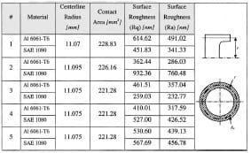
Table 2 Surface roughness for Aluminum 6061-T6 sliding against Steel SAE 1080
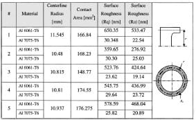
Table 3 Surface roughness for Aluminum Al 6061-T6 sliding against Al 7075-T6 mirror polished
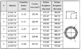
Table 4 Surface roughness for aluminum Al 6061-T6 sliding against Al 7075-T6 rough finished
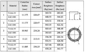
Table 5 Surface roughness for Titanium Ti 6Al-4V sliding against Steel SAE 1080
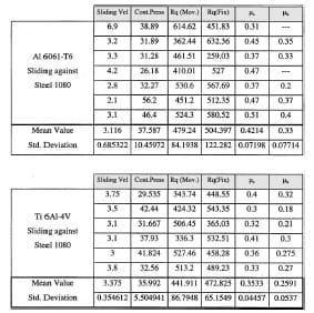
Table 6 Friction experimental results
References
- Komanduri, R., Merchant, M. E., and Shaw, M. C., 1993, “U.S. Machining and Grinding Research in the 20th Century,” Appl. Mech. Rev., 46, pp. 69–132.
- Komanduri, R., Schroeder, T., Hazra, J., von Turkovich, B. F., and Flom, D. G., 1982, “On the Catastrophic Shear Instability in High Speed Machining of an AISI 4340 Steel,” J. Eng. Ind., 104, pp. 121–131.
- Zukas J. A., 1990, High Velocity Impact Dynamic, John Wiley & Sons, New York.
- Meyers, M. A., 1994, Dynamic Behavior of Materials, John Wiley & Sons, New York, NY.
- Camacho, G. T., and Ortiz, M., 1996, “Computational Modeling of Impact Damage in Brittle Materials,” Int. J. Solids Struct., 33, No. 20–22, pp. 2899–2938.
- Espinosa, H. D., Dwivedi, S., Zavattieri, P. D., and Yuan, G., 1998, “Numerical Investigation of Penetration in Multi-Layered Structure/Material Systems,” Int. J. Solids Struct., 35, No. 22, pp. 2975–3001.
- Espinosa, H. D., Zavattieri, P. D., and Emore, G. L., 1998, “Adaptive FEM Computation of Geometric and Material Nonlinearities with Application to Brittle Failure,” Special Issue of Mechanics of Materials, H. D. Espinosa, and R. J. Clifton, Mech. Mater., 29, pp. 275–305.
- Prakash, V., and Clifton, R., 1993, “Time Resolved Dynamic Friction Measurement in Pressure-Shear,” ASME, AMD-165, pp. 33–48.
- Prakash, V., 1995, “Pressure-Shear Plate Impact Experiment for Investigating Transient Friction,” Exp. Mech., 35, No. 4, pp. 329–336.
- Espinosa, H. D., Mello, M., and Xu, Y., 1997, “A Variable Sensitivity Displacement Interferometer with Application to Wave Propagation Experiments,” J. Appl. Mech., 64, pp. 123–131.
- Ogawa, K., 1997, “Impact Friction Test Method by Applying Stress Waves,” Exp. Mech., 37, pp. 398–402.
- Feng, R., and Ramesh, K. T., 1993, “Rheology of Lubricants at High Shear Rates,” J. Tribol., 115, No. 4, pp. 640–649.
- Blau, P. J., 1992, “Static and Kinetic Friction Coefficients for Selected Materials,” ASM Handbook, Vol. 18, ASM International, Materials Park, OH, Appendix, pp. 70–75.
- Larsen-Basse, J., 1992, “Introduction to Friction,” ASM Handbook, Vol. 18, Friction, Lubrication and Wear of Materials, ASM International, Materials Park, OH, pp. 25–26.
- Larsen-Basse, J., 1992, “Basic Theory of Solid Friction,” ASM Handbook, Vol. 18, Friction, Lubrication and Wear of Materials, pp. 27–38.
- Anand, L., and Tong, W., 1993, “A Constitutive Model for Friction in Forming,” Ann. CIRP, 42, pp. 361–366.
- Anand, L., 1993, “A Constitutive Model for Interface Friction,” Comput. Mech., 12, pp. 197–213.
- Kolsky, H., 1963, Stress Waves in Solids, Dover Publications, New York.
- Duffy, J., Hawley, R. H., and Hartley, K. A., 1995, “The Torsional Kolsky (Split-Hopkinson) Bar,” ASM Handbook, Vol. 8, ASM International, Materials Park, OH.
- Gilat, A., and Pao, Y. H., 1988, “High-Rate Decremental-Strain-Rate Test,” Exp. Mech., 28, pp. 322–325.
- Patanella, A. J., 1998, “A Novel Experimental Technique for Dynamic Friction Studies,” M.Sc. thesis, Purdue University, West Lafayette, IN.
- Kumar, P., and Clifton, R. J., 1979, “Dislocation Motion and Generation in LiF Single Crystals Subjected to Plate Impact,” J. Appl. Phys., 50, p. 4747.
- Espinosa, H. D., Patanella, A. J., and Fischer, M., 2000, “A Novel Dynamic Friction Experiment Using A Modified Kolsky Bar Apparatus,” to appear in Exp. Mech. 40, No. 3, pp. 1–10.
- Madakson, P. B., 1983, “The Frictional Behavior of Materials,” Wear, 87, pp. 191–206.
- Martins, J. A. C., Oden, J. T., and Simo˜es, F. M., 1990, “A Study of Static and Kinetic Friction,” J. Eng. Sci., 28, No. 1, pp. 29–92.
- Brechet, Y., and Estrin, Y., 1994, “The Effect of Strain Rate Sensitivity on Dynamic Friction of Metals,” Scr. Metall. Mater., 30, No. 11, pp. 1449–1454.
- Ludema, K. C., 1996, Friction, Wear, Lubrication, CRC Press, Boca Raton, FL.
- Rabinowicz, E., 1951, “The Nature of the Static and Kinetic Coefficients of Friction,” J. Appl. Phys., 22, No. 11, pp. 1373–1379.
- Rabinowicz, E., 1995, Friction and Wear of Materials, John Wiley & Sons, New York.
- Rajagopalan, S., Irfan, M. A., and Prakash, V., 1999, “Novel Experimental Techniques for Investigating Time Resolved High Speed Friction,” Wear, 225-229, pp. 1222–1237.


