

Article
Related Links
Maria MARTINEZ PACHECO, Rector Magnificus, voorzitter
Prof. ir. L. Katgerman, Technische Universiteit Delft, promotor
Prof. Dr. Eng. J.M. Torralba, Universidad Carlos III de Madrid (Spanje)
Prof. dr. ir. L. Froyen, Katholieke Universiteit Leuven (België)
Prof. dr. R. Boom, Technische Universiteit Delft & Corus
Prof. dr. ir. H.J. Pasman, Technische Universiteit Delft
Prof. dr. J. Schoonman, Technische Universiteit Delft
Dr. ir. R.H.B. Bouma, TNO Defensie en Veiligheid, adviseur
Introduction
Combustion or burning may be a complex sequence of rapid exothermic and sometimes competing chemical reactions accompanied by the production of heat. One may observe a glow or even flames. A stable combustion propagates through a suitable medium and converts the reactants. This propagation results from the strong coupling of the reaction with heat release and the molecular transport processes in the combustion front.
Combustion can be achieved in gas-gas, gas-liquid, liquid-liquid, liquid-solid and even solidsolid systems. The burning of wood, plastics or fuels are examples of combustion of organic compounds. Combustion can also be achieved with inorganic compounds such as metals, non metals, oxides, borides, nitrites, etc.
There are a number of reaction parameters which influence the combustion process. Experimentally one may observe that a piece of wood easily burns when dried. However, if the wood is wet, an extra amount of heat will be needed in order to achieve the combustion of it. In both situations, the system “wood-oxygen” remains the same however, the system thermodynamics have changed. If the burning wood now is covered with a thick blanket, the combustion will be exhausted after a while due to a lack of oxygen being one of the two reactants. Now, the stoichiometry of the reaction is changed. Both are examples of how the combustion can be affected by the process parameters.
Combustion is accompanied by the release of heat. Since the discovery of the fire, combustion has been used basically as a calorific process. The products derived from that combustion have been used though unconsciously. For centuries the farmers have burned their fields in order to eliminate the weeds. In addition the terrain was for a period of time kept free of being sowed in order to give some relief to the castigated ground. The ashes produced from the burning of weeds, acted at the same time as a bio-organic fertilizer retrieving mineral salts needed to enrich the ground. In this way a natural recycling of the fields was achieved. One now may consider an inorganic combustion, “the aluminothermic reaction”. Men have been using for more than hundred years a mixture of iron oxide, and aluminum to weld rail tracks, see detail in figure 1. The result of the combustion of that powdered mixture was molten iron which could perfectly join the tracks. Technically the iron oxide is reduced by the aluminum to form aluminum oxide and iron metal. This practice is still in use as it requires no special equipment and is relatively cheap. In the 1960s it has been discovered that combustion of metals and/or oxides can be used as a process to synthesize composites, complex compounds, intermetallics, etc. Processes such as reactive sintering and self-propagating high-temperature synthesis have been developed since. The combustion process itself influences the microstructure and hence the mechanical, optical, electrical properties, etc., of the final product.
One may only benefit from the process itself i.e. the chemical reaction involved. The Chinese discovered the use of combustion of certain metallic powders to fabricate fireworks. Here, a first reaction provides a time delay, while the firework device is being propelled towards the sky, after a certain time this reaction will ignite the firework main charge. We as spectators, just observe a first flash corresponding to the firing of the fuse and few seconds later a colorful sparkling explosion spreading out in the sky. The study of the reaction kinetics provides instruments to model the combustion process. One can then vary the time delay when designing fireworks or airbags, the heat release and the rate of heat release when used as a source of energy, or the conversion into products when synthesizing materials, just by varying parameters that influence the chemical reaction involved.
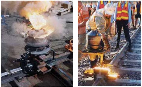
Figure 1: Thermite welding in the joining of rail tracks [1].
The burning of an energetic mixture can never be achieved without the initiation or ignition of the chemical reaction. Here not only thermodynamics and kinetics but also the hazards play an important role. Control of hazardous situations may avoid accidents. For instance, the substrate used to make movies in the early 20th century was nitrocellulose, a very unstable and high flammable material. Many of these movies were lost forever due to violent fires as nitrocellulose in air does gradually decompose leading finally to its spontaneous ignition. The hazard of an energetic material in a given situation depends on its sensitivity, i.e. ease of accidental ignition, and on the violence of the event following an ignition. No matter the likelihood of an event, precautions must be taken to ensure that the event can be contained, and personnel are isolated from it, if it happens. In order to control hazardous situations test methods have been developed to study the initiation thresholds of combustible materials. Unfortunately, no single sensitivity test gives an adequate picture of the precautions that must be taken when handling an energetic material.
Combustion reaction
Energetic substances may be divided in three main classes: explosives, propellants and pyrotechnics. They all possess the characteristic of ready chemical decomposition to produce a large amount of heat and often considerable quantities of gas. They derive their energy from a chemical reaction between reactants which are present in the energetic material itself. The reaction does not depend upon the availability of oxygen from the air. Explosives are designed to release their energy as rapidly as possible, and the shock to the environment and the expansion resulting from the creation of very hot gas produce the required destructive effect. They are designed to detonate to produce the maximum rate of energy release as a shock wave. The detonation travels at above the sound velocity in that material, typically 6000-9000 m·s-1. Propellants produce hot gas but release their energy much more slowly than explosives so that the energy of expansion can be harnessed as a control thrust. They are designed to burn at a controlled rate and provide a predefined thrust to the system containing them. Pyrotechnics provide much more
varied effects only some of which are primarily due to the production of gas: in fact important groups of pyrotechnics ideally produce no gas. The purpose of pyrotechnics is to produce heat per se, light, sound, smoke, gas, motion, chemical synthesis, or combinations of these. Pyrotechnic compositions are mixtures of ingredients, which usually are not themselves explosive, and are designed to burn but not to detonate. Typical burning rates of pyrotechnics can vary from below 1 mm·s-1 to greater than 1000 mm·s-1.
The basis of pyrotechnics is a reaction which can be made to take place between two or more ingredients, specifically these will include a fuel and an oxidizing agent. The reaction between these produces heat as the mixture of reactants is converted into a mixture of solid, liquid or gaseous reaction products. In a pyrotechnic reaction when the first layer of reactants is ignited, the reaction zone moves into the unreacted composition leaving behind it the combustion products. If the chemical reaction generates enough heat to ensure that adjacent layers of reactants reach ignition, then the propagation of reaction becomes self-sustained and the pyrotechnic mixture will burn from end to end e.g. supposed a pyrotechnic mixture compressed within a tube. This combustion process, characterized by the passage of a high temperature region driven by heat transfer phenomena without an accompanying pressure wave, must be distinguished from an explosion, where the pressure is prominent, and from a detonation which propagates by means of a shock wave in the reactants. However, one should not forget that a pyrotechnic composition can be made to detonate i.e. some pyrotechnic compositions containing aluminium powder can detonate as a dust cloud in air. It should be noted that their energy content is comparable to that explosives; the major difference is the rate at which it is released, see table 1.
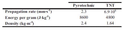
Table 1: Comparison of the output of a pyrotechnic with that of an explosive i.e. TNT [2].
Self-sustained High-temperature Synthesis
Self-sustained High-temperature Synthesis – Pyrotechnic reactions producing solid compounds by means of solid phase reactions are known as the Self-sustained High-temperature Synthesis (SHS) process. The SHS process was initially developed on the basis of a scientific invention. In 1967 Borovinskaya, Skhiro and Merzhanov at the Institute of Chemical Physics of the USSR Academy of Sciences in Chernogolovka, discovered a new type of reaction between solid reactants in the mode of combustion yielding solid products. One of the initial observations was the violent reaction between titanium and boron yielding titanium diboride (Ti + 2B ? TiB2), in which the product was found to retain its original shape with a hard and relatively dense body. Scientists soon realized the potential of such a simple process and began to investigate the synthesis of other high value ceramic materials [3].
The SHS process looks rather simple. It can be performed in a system reacting in the mode of wave propagation due to heat transfer from hot products to cold reactants after local initiation (ignition) of the process. In a typical sequence of SHS, three main stages of the process i.e. ignition, front propagation, and product cooling are clearly separated. The typical characteristics of SHS are presented in table 2. The maximum combustion temperature Tm, the velocity of front propagation U, and the heating rate may attain very high values, which allow one to consider SHS as an extreme chemical process.
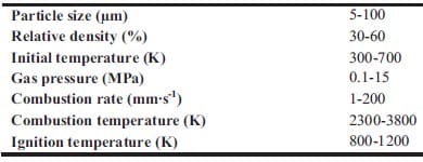
Table 2: Typical characteristics of the SHS process [4].
A range of elements such as titanium, boron, molybdenum etc., may be prepared by the SHS process. Particularly interesting is the application to the synthesis of inorganic compounds such as borides, carbides, nitrides and silicides; intermetallics and alloys; oxides such as niobates, tantalates, ferrates; hydrides, etc.. Many materials of practical importance for electronics, armour, chemical engineering and many other applications are accessible by this method.
The apparently simplicity of the SHS process hides the highly complex chemical and physicochemical transformations influencing both the combustion velocity and quality of final products. A synthesized product is easy obtained by the SHS method by understanding the overall reaction scheme. But to obtain the SHS product that meets strict demands on the chemical and phase purity, contaminations, microstructure, physical (or service, in the case of net-shape production) parameters, an enormously difficult task that requires the extensive scientific research have to be achieved. SHS represents a self-adjusting process, in which the product formation generally is both a cause and a consequence of combustion.
Scope and outline of this thesis
The goal of this Ph.D. work is to find and optimize a densification stage which combined with self-sustained high-temperature synthesis can lead to dense ceramic-metallic composites i.e. cermets. In addition, a study of the process kinetics as well as the sensitivity to initiation of reactive mixtures will be carried out in order to design and control efficiently the process.
Experimentally it has been observed, that porosity in the reactant mixture is needed for the reaction front to propagate. Furthermore, due to the exothermicity of the process and the increased density of the reacted material, the final product is characterized by a large remaining porosity (typically 50%). In order to produce dense ceramics or cermets, there is a need for a subsequent densification step which is often hard to achieve in ceramic composite materials due to their high deformation resistance. A densification pressure must be applied within seconds after the self-sustained high-temperature reaction when the temperature of the final product is still above the ductile-to-brittle transition temperature and/or the melting temperature of the metallic phase, which acts as a binder. Experiments have been performed to produce TiC and TiB2-based cermets by self-sustained high-temperature synthesis starting from the pure elements: titanium, carbon and boron and the admixing of inert metallic powders. The time-window for densification is determined by the end of the combustion process on the one hand, and the solidification of the final product on the other hand.
The control of the combustion wave propagation velocity and temperature, the composition and structure of the reacted material ensures the high-quality products. Nowadays the control of combustion velocity is performed by applying the modern concepts of the combustion theory of chemical reactions.
During the last decade the term Metastable Intermolecular Composites (MICs) has been adopted to define thermite mixtures e.g. Al + MoO3, on the nanoscale. Nano particles can drastically change the kinetics and propagation characteristics increasing the reaction velocity of reactive mixtures. Researchers have paid special attention to the ignition characteristics and propagation behaviour of MICs. It have been demonstrated that the ignition time can be significantly reduced in mixtures containing nano-sized particles (10-100 nm) instead of micronsized particles. So far, no detailed understanding exists on the ignition mechanisms of energetic solids when subjected to high deformation rates. Various models have been proposed to describe the behaviour of energetic solids to rapid deformation. Essentially, the models are developed for explosives and propellants as these are more sensitive to impact than common pyrotechnics. However MICs present promising in this field due to their enhanced sensitivity to ign
ition by impact.
In chapter 1 an introduction into the fundamentals of self-sustained high-temperature synthesis is given. In addition, typical densification techniques combined with self-sustained high-temperature synthesis in order to remove porosity of the final product are described. The focus will be finally on the so-called quasi-isostatic pressing technique. Here a granulate medium is used to transfer pressure to the sample as well as to provide thermal isolation. In order to design the time-window for densification, the thermal processes involved are studied by performing numerical simulations. These are carried out with the finite element code ABAQUS focusing on the physics of the heat generation and heat conduction process in Self-sustained High-temperature Reactions. The numerical simulations are specific for TiC and TiB2-based cermets.
Chapter 2 and 3 present experimental results on the preparation of cermets obtained by selfsustained high-temperature synthesis followed by quasi-isostatic pressing in a granulate medium. The synthesis of functionally graded TiC-based cermets for armour applications is described in chapter 2. In addition, pressure sensor films are used in order to study the pressure distribution along the granulate medium when an uniaxial load is applied. Chapter 3 deals with the fabrication of TiB2-based cermets for electrical contacts applications. Firstly the arcing phenomenon and different arcing contact materials are described. Then a materials selection is performed based on electrical conductivity estimations for composites. The model used is based on the complex dielectric behaviour of heterogeneous materials. Mechanical and electrical properties of TiB2-40wt.%Al, TiB2-30wt.%Al, and TiB2-40wt.%Cu are evaluated as well.
The kinetics of self-sustained high-temperature reactions is studied in chapter 4. Here an introduction into the theory of combustion wave as well as the fundamentals of homogeneous combustion of condensed substances, are given. Various analytical models for the combustion wave propagation are presented. Predicted values of propagation wave velocity based on a theoretical model are compared with experimental measurements for the Ti + 2B and Ti + C based system. Al and Cu are used as diluents and their concentrations are varied systematically. The experimental part is based on initiation and propagation of the combustion wave through a stack of cylinders with decreasing diameter. The effect of metal additions, diluent particle size, green density, and geometry is determined by measuring the combustion wave propagation velocity. Besides activation energy and pre-exponential factor term describing first order kinetics have been experimentally determined for one of the studied systems.
Chapter 5 and 6 deal with the experimental determination of sensitiveness to initiation of reactive mixtures. The initiation of a chemical reaction due to mechanical deformation at impact is described in chapter 5. The Ballistic Impact Chamber Test is used to study experimentally the deformation and sensitivity to impact of thermite mixtures without the need of complex computer simulations and supposing than shear rate is the parameter that controls initiation. Mixtures considered contain nano-sized Al, and nano or micron-sized MoO3 at different ratios. Finally the effect of impact velocity, green density, addition of a polymeric binder, MoO3 particle size, and fuel/oxidizer ratio, on the sensitivity of the Al / MoO3 mixtures towards mechanical deformation is determined. In chapter 6 experiments are focus on determining the spark sensitivity of various Ti + C and thermite mixtures. Electrostatic discharge measurements are performed with a dedicated apparatus. The electrostatic discharge sensitivity of the materials strongly depends on the particle size and on mixture preparation techniques and hence mechanical treatments will enhance sensitiveness. In this chapter is it observed the effect of stoichiometry on sensitiveness of mixtures to electrostatic discharge and the effect of the spark pulse duration on the initiation behaviour of mixtures.
References
- AustralAsia Railway Corporation: www.aarc.com.au/…/photolib/photos_thermit.html
- Davies N.: “Pyrotechnics Handbook”, Department of Environmental and Ordnance Systems, Cranfield University, Royal Military College of Science, January 2004.
- Merzhanov A.G.: “The Theory of Stable Homogeneous Combustion of Condensed Substances”, Combust. Flame, 13 (1969), pp.143-156.
- Merzhanov, A.G., “The Chemistry of Self-propagating High-temperature Synthesis”, J. Mater. Chem. 14 (2004), pp. 1779-1786.
Chapter One
Ceramic-metallic materials (cermets) can be synthesized using highly exothermic chemical reactions. Preparation of cermets is done by gasless combustion, also known as Self-propagating High-temperature Synthesis or Combustion Synthesis. Volume Combustion is not considered in this thesis. Experimentally it has been observed, that porosity in the reactant mixture is needed for the reaction front to propagate. Furthermore, due to the exothermicity of the process and the increased density of the reacted material, the final product is characterized by a large remaining porosity (typically 50 %). In order to produce dense ceramics or cermets, there is a need for a subsequent densification step, which is often hard to achieve in ceramic composite materials due to their high deformation resistance. Therefore, the densification pressure must be applied within seconds after the Self-sustained High-temperature Reactions when the temperature of the reacted material is still above the melting temperature of the final product or one of its constituents.
In this chapter various consolidation techniques will be reviewed. Here the focus will be on quasi-isostatic pressing as a consolidation technique after combustion synthesis. A better understanding of the thermal processes involved is needed to design the process. Numerical simulations are carried out with the finite element code ABAQUS focusing on the physics of the heat generation and heat conduction process in Self-sustained High-temperature Reactions.
Comparison of experiments with detailed numerical modelling is aimed to find the limits of gasless combustion processes in relation to the material properties. In this chapter, an estimated time-window for TiB2 and TiC-based cermets is presented. Al, Cu and a NiFe alloy are used as the binder phase of the final cermet. One should note that the available time-window for densification is not only a function of thermodynamic properties, but depends on the total volume of the reactants. In this way, the time window can be tailored to achieve good product properties. The application of pressure may vary to some extent the time-window for densification due to compaction of the isolator. This effect has not been taken into account in the numerical simulations.
In paragraph 1.1 a brief introduction is given into self-sustained high-temperature synthesis and densification. The combustion synthesis process is reviewed in paragraph 1.2. Typical densification techniques used to remove porosity of the synthesized material are described in paragraph 1.3, in particular for TiC-based cermets. In paragraph 1.4, a numerical simulation is performed regarding the available time window to consolidate the hot sample. The outcome of the numerical simulations for the preparation of TiC and TiB2-based cermets is also discussed here. Finally, conclusions are drawn in paragraph 1.5.
1.1. Introduction
Processes leading to the formation of materials as a product of a reaction are numerous. Examples of these are: 1) common furnace processes with reactant systems at a constant or increasing temperature, 2) plasmo-chemical synthesis, 3) reactions in sh
ock and detonation waves, etc. In this thesis attention is paid especially to the so-called Self-propagating Hightemperature Synthesis (SHS), also known as combustion synthesis [1]. The main advantages using SHS as a method to synthesize advanced materials are:
- The products obtained with this process are more pure due to the high temperatures achieved, which can volatilize the low boiling point impurities.
- The process is simple with no very special equipment requirements.
- The times employed are short compared to traditional techniques such as sintering, typically in the order of seconds, resulting in low operating and processing costs.
- The high thermal gradients and rapid cooling rates can give rise to new nonequilibrium or meta-stable phases that are not accessible by conventional processing.
- Inorganic materials can be synthesized and consolidated into a final product in one step by utilizing the chemical energy of the reactants.
- The large porosity of the final products can be required for some product applications.
In particular applications the large porosity characteristic of SHS products i.e. typically 50 %, can be a drawback. Porosity is the result of one or more of the following parameters:
- The lower specific volume of the products introduces shrinkage, which means an intrinsic increase of the porosity. Typically, this shrinkage is about 20-25 % of the reactants volume.
- Porosity in the reactant mixture is necessary for both ignition and propagation. It is known that the higher the initial density the larger is the thermal conductivity of the samples. Combustion of the specimens starts when a certain amount of heat becomes localized and some melt is achieved. If the conductivity of the material is too large, this amount of heat is rapidly dissipated away from the ignition source and temperatures are too low to achieve proper ignition. In that case, solid-state diffusion reactions are still possible. When the starting powders are too dense, an additional heat supply will be essential for the ignition as well as for the propagation of the SHS reaction. In some applications, SHS is carried out inside an oven.
- Impurities in the reactant powder mixture will be volatilized due to the large temperatures reached during SHS (> 2000 °C). As a result of it the porosity will increase.
- The heat generated during the SHS reaction leads to an increase in the sample temperature, which directly lead to a substantial internal pressure (several bar).
In order to produce a dense material, a consolidation or densification stage must be included in the fabrication process and several methods exist. Combustion synthesis can be combined with hot-pressing, extrusion, quasi-isostatic pressing (QIP), hot-isostatic pressing (HIP) or shock wave compaction. In order to achieve a dense material these consolidation techniques must be applied when the sample is still hot and above its ductile-to-brittle transition temperature (DBTT) or close to the melting point when dealing with ceramic compounds or metals, respectively. Only under these circumstances, the combustion product shows a plastic behaviour and the densification stage can be successfully applied.
1.2. The Self-sustained High-temperature Synthesis process
1.2.1. General concepts
A trend to utilize the heat released in chemical reactions in manufacturing useful products has long been known, since the last century when Beketov and Goldschmidt discovered the selfsustaining thermite reactions yielding condensed products. Later on, a number of prominent production processes based on combustion were suggested (blast furnaces for pig iron production, aluminothermic production of ferroalloys, or gases for industrial applications, etc.). However, prior to the development of the modern combustion theory treating unconventional patterns of exothermic processes (1930-40s for gases, and 1950-60s for condensed media), it was difficult to evaluate the prospects and potential of such an approach to production processing. As a result, the individual and independent scientific papers devoted to the exothermic phenomena that had been appearing since the time of Beketov and Goldschmidt as a rule were of an insufficiently high level and had no appropriate technological consequences [2].
The SHS method was developed on the basis of a scientific invention. In 1967 at the Branch of the Institute of Chemical Physics of the U.S.S.R. Academy of Sciences in Chernogolovka, researchers, who were investigating new models of combustion in condensed media, discovered a new type of reaction between solid reagents. It was a combustion process yielding solid products. Later this process was called the ‘Solid Flame Phenomenon’, meaning a very important step in the development of combustion theory. Numerous scientific directions were developed on the basis of solid flame studies: non-equilibrium theory of flame propagation (which gave explanation to the solid flame phenomenon), the theory of infiltration-aided combustion, the theory of heterogeneous combustion, and modeling studies of unsteady combustion together with experimental diagnostics [1]. Work in the area of SHS was started by using mixtures of metals with boron, carbon, and silicon. SHS was closely associated with the combustion science and its terminology was widely used, due to this fact SHS was initially termed ‘Combustion Synthesis’.
Since 1976, a large number of universities and laboratories in Russia, the former U.S.S.R., and later on worldwide have been engaged in the research and development of SHS. So far, over 600 compounds have been reported to be synthesized by SHS.
Combustion synthesis reactions can be classified depending on the state of reactants in solidsolid or gasless, solid-liquid and solid-gas reactions.
Furthermore, combustion synthesis reactions are classified according to the type of reaction system involved as: 1) elemental systems, in which the material is synthesized from its elements, 2) thermite systems, in which the combustion synthesis involves a reduction stage, usually metallothermic reduction of an oxide, 3) complex reaction systems, involving several and competing reactions [3]. Combustion synthesis may occur in two different modes:
Self-propagating mode often referred to as SHS
The energy input which is applied in a small but sufficient large volume of the reactant sample increases the local temperature to the ignition temperature of the mixture. From that moment, due to its self-sustained nature, the reaction does not need further energy input. The generated heat passes onto the next layer of unreacted composition and raises its temperature until its ignition is again achieved. The representation of the process is given in figure 1.1. The front of the SHS reaction moves towards the unreacted mixture leaving behind the combustion products, and separates the heat-affected zone and the reaction zone.
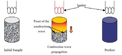
Figure 1.1: Schematic representation of the self-propagating mode [4].
Self-propagating mode often referred to as SHS
The sample is placed in a furnace and uniformly heated to the ignition temperature of the mixture at which point the energy input ceases. The process is represented in figure 1.2. As main characteristic of this mode, the entire sample will simultaneously react as a bulk with no propagation of a front.
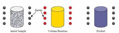
Figure 1.2: Schematic representation of the simultaneous combustion mode [4].
1.2.2. Thermodynamics
The combustion temperature associated with the SHS reaction is related to t
he enthalpy change between the reactants and products. During the combustion synthesis reaction, four important temperatures should be described:
- Initial temperature T0 is the average temperature of the whole reactant sample before the ignition takes place.
- Ignition temperature Tig is the temperature at which the reaction is initiated. It is dependent on the kinetic characteristics of a reaction, such as reaction type, i.e. solidsolid, solid-gas, solid-liquid or liquid-gas reactions.
- Adiabatic combustion temperature Tad is the maximum temperature achieved under adiabatic conditions. Its value is related to thermodynamics (exothermicity) and the initial temperature of the reactant sample.
- Actual combustion temperature Tc is the maximum temperature achieved under nonadiabatic conditions. It is kinetically controlled since it will be dependent on heat losses from the reaction front.
The temperatures T0, Tig and Tc are usually measured directly from the SHS reaction experiments, while the adiabatic temperature Tad can be determined by thermodynamic calculation provided the initial temperature is known. The relationship between the temperatures and the enthalpies of the reactants and products achieved during the process is shown in figure 1.3.
Assuming that the reaction occurs in a propagating mode and under adiabatic conditions, the heat needed by the reactants to increase their temperature from T0 to Tig in order to have the reaction initiated is represented by the formula:
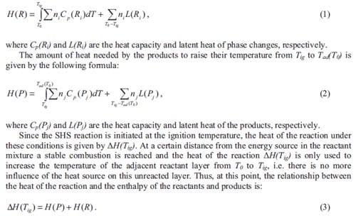
Increasing T0 to Tig will decrease H(R) to zero and all of ΔH(Tig) will be available to be absorbed by the products, resulting in an adiabatic temperature of Tad(Tig), see figure 1.3. Under these conditions, the reaction is ignited under the simultaneous combustion mode. It can also be observed in figure 1.3 that increasing the extent of pre-heating will increase the adiabatic temperature that can be theoretically achieved by the combustion synthesis reaction. It has been demonstrated empirically that the adiabatic temperature has to satisfy the condition Tad = 1800K to achieve a self-sustained reaction [3]. Generally, the reaction will take place under nonadiabatic conditions, especially in the propagating mode; therefore, the heat generated in the reaction will not only dissipate to the adjacent reactant layer, which is still below Tig, but also to the surroundings as heat losses.
Furthermore, considering heat generation and heat exchange, one may observe that ignition will take place when the rate of heat arrival from an external source equals the rate of heat generated from the chemical reaction. Thus, ignition depends not only on the chemical characteristics of the reactant mixture but also on the energy of the initiating heat pulse used to ignite the exothermic reaction. Hence, the thermodynamics properties, e.g. free energy and enthalpy, and physical states of the reactants, e.g. solid, liquid and gaseous, and surface area of reactants are important parameters. It has been experimentally demonstrated [5] that the ignition energy needed to ignite a bulk condensed system i.e. a low reactant surface area, is one to two orders of magnitude higher than that for a powdered system i.e. a high reactant surface area. This difference is due to the significant heat losses that are incurred in igniting a bulk condensed reactant system, and high ignition temperatures are expected.
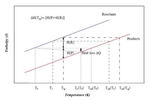
Figure 1.3: Schematic representation of the Enthalpy-Temperature plot for reactants and products in a reaction system that involves no phase changes in reactants and products [5].
The rate of wave propagation, wave stability and maximum combustion temperature achieved in SHS reactions are dependent on the generation and heat losses from the reaction front as well as the thermochemical properties of the system. Decreasing heat generation (exothermicity) and/or increasing the heat dissipation can create instabilities and may result in slowing down or temporarily halting the propagation of the combustion wave, or even quenching of the reaction.
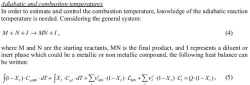
where T is the temperature (K), XI is the mass fraction of diluent, Cp is the heat capacity of product or diluent (J·kg-1·K-1), L is de latent heat of phase changes (J·kg-1), ? is the mass fraction of product or diluent subjected to phase changes, and Q is the heat of reaction (J·kg-1) with respect to the undiluted reactants. The indexes i and j represent the different phase changes of product or diluent, respectively.
Integrating equation (5) one obtains the adiabatic temperature of a determined system. Based on equation (5) for the Ti + C + Ni –> TiC + Ni system and supposing that the heat capacities of product and diluent are temperature independent, the adiabatic temperature profiles plotted in figure 1.4 have been calculated. The initial temperature T0 is equal to 300 K. The various curves represent the evolution of the adiabatic temperature as a function of the diluent additions for the considered system supposing product phase changes (Vi MN > 0), diluent or metal phase changes (Vj I > 0), or product and diluent phase changes (Vi MN and VjI > 0). The thermochemical data used to calculate the adiabatic temperature evolution can be found in [6]. Although the combustion temperature will be lower than the theoretical adiabatic temperature, these plots give essential information in order to be able to control of the combustion temperature of a system. Figure 1.4 indicates that the content of nickel can never be larger than 70 wt.% to achieve a selfsustained reaction at room temperature. Usually the final product (TiC) does not melt during the SHS reaction as a result, the nickel content has to be even lower (60 wt.%).
For any application, considering combustion synthesis as a method to produce materials, the maximum combustion temperature or the final state of the system plays an important role in determining the microstructure and properties of the products. Low combustion temperature may lead to incomplete reaction resulting in complex products. High combustion temperature may lead to a liquid product causing shape change, heterogeneous coarse microstructure and large shrinkage voids. On the other hand, high combustion temperature and complete melting of the product may be necessary in e.g. joining or coating applications.
Furthermore, the study of the propagation mode of the SHS reaction for a reaction system is essential as it can as well influence the microstructure of the final product, and hence its properties.
Figure 1.4: Evolution of the adiabatic temperature of a Ti + C + xMetal system as a function of the inert metallic phase content (x).
Propagation modes
In a steady-state mode, i.e. without instabilities, the combustion wave moves from the ignition surface through the reactants at a uniform velocity. A non-steady-state mode is defined as a nonuniform velocity of the combustion front with respect to time and/or space and may lead to the extinction of the combustion reaction. The non-steady-state mode can be manifested in three different forms:
- Oscillating or pulsating, when the wave moves in successions of rapid and slow displacements. The resultant products will possess layered structure, which is easily broken into discs.
- Spinning, when the reaction proceeds in a spiral motion from one end of the sample to the other. Given that the spiral motion may be predominantly associated with a surface reaction, the bulk of the sample can remain largely unreacted after the passage of the reaction front.
- Repeated combustion wave front movements, when there is a second passage of the combustion wave through the already reactive substance, following the propagation of the first combustion wave in the original reactant materials. The first combustion wave is relatively fast and localized along the exterior surface, while the second wave is slower and the combustion zone is much broader. This instability is related to the kinetics of the reactions, and normally comes along in solid-gas reactions.
The kinetics of a combustion wave travelling at uniform velocity will be treated in detail in chapter 4.
Propagation modes
There are a number of reaction parameters, which may influence the SHS reactions. Establishing the optimum reaction parameters for synthesizing a material is based on obtaining a fundamental understanding of the controlling reaction mechanisms in each SHS reaction system.
Particle size
Since SHS reactions are normally performed using a powder compact, the particle packing characteristics play an important role in controlling the green density, green pore size, thermal conductivity of the reactants and the products, and inevitably affect the consolidation and properties of the final products. The particle size distribution significantly affects the packing density. When smaller particles are introduced in the interstices of the larger particles, the packing density increases and the porosity and pore size decrease substantially.
In a combustion synthesis reaction, one or more of the reactant species is normally metal which may melt before the exothermic reaction is initiated. Experimentally it has been observed that the SHS reaction is triggered and facilitated by the melting of the metallic powders and the subsequent spreading of the liquid over the surfaces of the ceramic solid powders. That is the case of the Ti + C –> TiC system. In such a system, Moore et al. [5] and Munir et al. [7] have been reported that there are two modes of combustion: diffusion mode and capillary action mode. Which of these modes is dominant depends on the particle size of the metallic reactant, being dominant the diffusion mode for smaller particles.
In the diffusion mode, the reaction is controlled by diffusion processes between the reactants, while in the capillary action mode the combustion reaction is controlled by the rate of the capillary spreading of the molten phase (metal) through the particles of carbon. Therefore, the particle size determines the reaction mechanism, which, in turn, controls the velocity of the propagating combustion wave. The relationship between the velocity u and metal particle size r0 has been demonstrated by Moore et al. [5] for the Ti + C ? TiC system. This relationship for three particle sizes of carbon r1, r2 and r3 is plotted in figure 1.5. There are three regions represented in this plot:
- The kinetic region, where the diffusion controlled mode is dominant and the velocity is independent of r0.
- The transition region, where u dramatically decreases as r0 increases.
- The capillary region, where the dependence of front velocity on r0 is relatively weak.
The particle size r0 at which the transition from region I to region II occurs, increases as r1, r2 and r3 increases. In general, the finer the reactant particles are, the larger is the surface area available for reaction, and, the faster the system tends to react [8].
Moore et al. [5] has reported for the Si + C ? SiC system that the particle size influences not only the rate of the reaction but also the nature of the product formed, decreasing the product particles with decreasing the particle size of the reactant particles. Raman et al. [9, 10] studied for the Ti + C –> TiC system the effect of Ti particle size on green density, ignition times as well as cracking tendency. It was found that using ultra-fine Ti powders a more violent initial ignition was achieved than using courser Ti powders; besides the latter decrease the combustion wave velocity; this might be the reason for a reduction in cracking. However, for coarser Ti particles i.e. between 105 and 150 µm, fewer cracks are observed when finer Ti particles are considered. For coarse Ti powders there is no significant difference in green densities or in ignition times by varying the particle size of Ti.
Figure 1.5: Schematic representation of the combustion rate as a function of the particle size of metallic reactant (r0) for various non-metallic reactant particle size (r1, r2 and r3) [5].
Green density
The final product morphologies and properties obtained by SHS reactions are also dependent on the reactant particle processing, which includes mixing and compaction of the green powders as most important stages. There are two techniques usually used to handle powder processing: dry and wet processing. In dry processing, powders may form agglomerates of non-uniform size and distribution because of the Van der Waals attractive forces present between particles. Since interparticle forces increase as the particle size decreases, dry powders are typically vibration mixed, ball milled or V-blended according to the characteristics of the powders, in order to achieve thorough mixing. In wet processing, the particles are dispersed in a liquid and, as such, are free to move in relation to each other in a manner largely determined by the viscosity of the liquid, and the solid concentration in the suspension. The resulting colloidal suspension is often ultrasonically mixed, which is accomplished by exposing the suspension to an inert solid mass vibrating at a high frequency, or by jet milling. Such mixing can break up agglomerates and reduce batch particle size. The green density of the reactants prepared by either of these processes can vary significantly, and will affect the thermal diffusivity of the reactant species and the overall SHS reaction.
Green compacts produced with significantly high or low densities are often difficult to ignite. The effect of green density on ignition and propagation behaviour is attributed to a balance between having enough particle contact to aid the reaction but not too much to lead to excessive heat loss from the reaction zone due to increased thermal conductivity. Thus, at low relative densities, the velocity of the thermal wave and the combustion reaction temperature achieved are expected to be low, and at high relative densities the effective thermal conductivity is so high that heat is conducted at such high velocity to distant regions ahead of the wave making it impossible to reach the ignition temperature in the layer immediately ahead of the wave. Therefore, highly dense reactant powders cannot be ignited.
The mechanisms of combustion in loose and compacted powder are explained in [11] and their scheme is depicted in figure 1.6. When a container is filled with loose powder, upon initiation of the prime ignition stimulus the particles immediately beneath the stimulus are ignited, reacting, and generating hot combustion products, which are free to ignite surrounding particles throughout the void spaces in the filling. The low bulk density of the filling, the turbulence
caused by the combustion process and the consequent ignition of the powder at many sites remote from the prime stimulus means that the combustion rate is very rapid. The confinement offered by the container causes the process to occur under pressure and an explosion will generally result. The combustion process shown on the right side of figure 1.6 is in contrast much slower and controlled. This is because the powder has been compacted by pressing it into a tube to a density approaching its theoretical maximum density (TMD), and the void spaces throughout the composition have therefore been reduced. In a pressed composition, the products of the combustion are unable to travel far into the consolidated column and combustion is confined to a relatively thin propagation zone known as the burning or combustion front.
Figure 1.6: Figurative representation of the combustion of loose (left) and compacted powder (right) [8].
The green density may markedly affect the kinetics of the SHS reactions, but its effect is often complex. If the combustion reaction is purely solid phase (i.e. no melting in the combustion zone) then increase in density should allow better contact between the reactants, and the reaction rate should increase. If the reaction is not solid phase, then the effect is less predictable.
Moore et al. [5] has reported that changes in the green density also affect the microstructure of the products.
Moisture and impurities involved in the process
Since impurities and, possibly, moisture may be present on the surface of particles in a green compact, the evolution of gaseous species in the sample, particularly at high combustion temperatures, can result in structural imperfections in the product. Thus, the pre-combustion treatment of a green compact is often extremely important in controlling the microstructure and properties of the SHS synthesized products. Such treatment usually involves heating the green body at a certain temperature in an appropriate environment for a few minutes to several hours, depending on the compact consolidation method employed. Therefore, physically and chemically adsorbed species can be removed partially or completely from the surfaces of the reactants, such that residual fluid from colloidal processing or environmental humidity can be evaporated in air or vacuum.
The outgassing behaviour and the nature of the volatile species associated with the combustion synthesis have been studied by many researchers. The rapid and large volume expansion of the adsorbed gases present on reactant particles and as the entrapped gases at particle-packing interstices is the principal cause of product elongation and even disintegration (explosion). A higher green density may further lead to a worse situation by making it more difficult for the gases to escape. The pressure inside internal pores can be even higher if one of the components melts since the capillary action of the liquid phase significantly reduces the outgassing permeability. The vapour trapped inside the isolated (closed) pores can enhance sample exfoliation and even lead to explosion due to the high pressure difference between the inside and outside of the pores.
Phase changes of the reactants and/or products
The phase transformations occurring in the reactant or product phases affect the temperature profile of the combustion reaction. Munir et al. [7] explains two types of phase transformations, the first type involve cases in which phase transformations occur below the ignition temperature i.e. ahead of the combustion front, and the second type relates to cases in which the transformations take place in the combustion front as a result of the sudden rise in temperature. Munir demonstrated that phase transformations which occur before ignition, hardly influence the temperature profile. These transformations may include, for instance, the α –> ß transformation of titanium during the synthesis of various compounds of titanium for which the Tig > 1155 K. An example of the second type may be the melting which takes place as a result of the combustion reaction.
Stoichiometry and use of diluents
Any excess of either reactants or products will decrease the exothermicity of the reaction, with a consequent reduction in the adiabatic temperature through a reduction in the heat liberated per unit mass of reactant powders. The use of an excess or deficiency of reactants not only influences the combustion temperature and propagation rates, but also results in unexpected products [5]. A diluent is a material that may not take part in the combustion reaction, but it will serve as a heat sink, removing thermal energy from the burning front and slowing the combustion reaction. The addition of an excess product as a diluent is mostly used to control the reaction process, e.g. decreasing the adiabatic temperature and making the reaction less violent, in order to achieve the desired microstructure and properties.
Attempts to fabricate dense TiC-xNi cermets in a single processing operation are made also by Han et al. [12]. Here, a study to determine combustion wave velocity and temperature values in Ti + C + xNi systems is performed. The Ni content is varied from 0 to 50 wt.%. It is found that with increasing Ni additions, both the combustion wave velocity and temperature decrease.
Exothermicity
The exothermicity is defined as the energy released per gram of reacting mixture. It is obvious that if the reaction is not adequately exothermic, combustion will not proceed. Therefore, the weakly exothermic reactions may require some special treatments to initiate and sustain the reactions. One of the techniques used to carry out this goal is to pre-heat the sample, for example by the passage of electrical current through the reactant mixture. Somewhat less exothermic mixtures can be made to propagate with a larger initial stimulus.
An increase in exothermicity, remaining other factors constant, leads to higher reaction temperatures, and hence higher temperature gradients. Because of this, the rate of heat conduction into the reactant mixture will be larger as well and as a consequence of this the propagation rate of the reaction will also increase.
Ignition techniques
There are many different techniques used to ignite SHS reactions, for example ignition by means of laser radiation, radiant flux, resistance heating coil, spark, chemical oven, etc. The technique used influences the ignition of the sample [13]. The energy stored in the first layer is important and is controlled by the heat flow from the ignitor to the sample and heat loss from the sample. Only when the stored energy is larger than a certain minimum, the sample will ignite. This minimum is determined by the activation energy of the system.
The ignition power input significantly influences the heating rate, which in its turn influences the combustion synthesis reaction. Using a high ignition power, the temperature of the top surface of the sample is raised relatively rapidly to the ignition temperature, while the rest of the pellet remains near room temperature. Therefore, as the reaction front propagates, more energy is lost by conduction to the cold unreacted part, leading to an incompletely developed nonequilibrium microstructure, which is similar to that achieved at low green density. Using a lower ignition power, pre-heating of the entire sample takes place and a fully reacted homogeneous microstructure is obtained, as in the case of high-density samples [5].
Moore et al. [5] stated that there are some essential differences in the product microstructure and properties when similar reaction systems have been ignited by these two different modes of combustion synthesis.
Thermal properties of the reactants and products
The specific heat and the thermal conductivity are important thermal properties influencing the propagation rate. It is expected that increasing the thermal conductivity of the mixture will increase its burning rate due to the pre-heating effects. The greater the thermal conductivity, the more rapidly heat is transferred from the reaction zone into the unreacted composition, so the smaller the fraction of heat loss. The width of the reaction zone should increase. The burning rate increases, but the ease of ignition decreases. In the case of the specific heat, the greater the specific heat of the composition, the greater the heat required to raise the next layer of composition to the ignition temperature. The temperature of the reaction zone is reduced, and the burning rate lowered. At highest thermal conductivity and heat capacity, ignition difficultly is achieved, and normally an increased intensity or duration of the ignition stimulus is required [8].
Ambient temperature and pressure
There are factors of primary importance imposed by the environment, which influence the SHS reaction and its combustion rate. The most important factors are the ambient pressure and the ambient temperature. All chemical reactions proceed faster at higher temperature, and combustion reactions propagate more rapidly at higher temperature. The ambient pressure only affects gassy compositions. In general, the gassier the system, the greater is the sensitivity of its burning rate to changes in the ambient pressure [8].
Geometry of the reactant sample and its container
Since heat losses during the combustion synthesis reaction significantly influence combustion temperature, propagation rates and stability, the geometry of the green reactant sample (especially surface area to volume ratio) becomes an important processing parameter.
In a cylindrical sample, the volume of composition generating heat is proportional to the square of the diameter, and the lost heat flux through the surface is proportional to the diameter. The ratio of the rate of heat loss to the rate of heat generation therefore increases as the diameter decreases. Moore et al. [5] has been reported that the combustion rate increased as the diameter of cylindrical sample increased, and remained constant after the diameter reached a certain value which was dependent on the reaction system.
Low combustion rates at small diameters are a result of high radial heat losses. Consequently, there exists a critical diameter below which the combustion wave becomes unstable and is finally extinguished. The size of the failure diameter will be increased by increasing the exothermicity and ambient temperature, and decreased by increasing the ignition temperature and the rate of heat loss.
The wall thickness is the most important geometric variable in the container, but its importance is less obvious. If the case is very thin, which means low thermal mass, conduction of heat along the wall can become critical and lead to radial burning with a dramatic change in the ignition and propagation times.
Thermal conductivity of the container
Highly conductive materials such as aluminium, copper or brass will transfer thermal energy along the length of the tube, heat the remaining composition and increase its burning rate.
Therefore, it is advisable to use low thermal conductivity materials such as stainless steel for the manufacture of the tubes to reduce theses effects [8].
1.3. Densification techniques
In this paragraph the main densification techniques based on a pressing stage after or while combustion synthesis occurs are summarized. Special attention is paid to application of these techniques to TiC-based cermets.
1.3.1. Densification induced by mass diffusion of shock modified powders
Although this technique may not include SHS as a synthesis process, can be considered within this category. Shock compression of powders, leads to a dense-packed highly activated state of the reactant mixture. The plastic flow, dispersion and mixture of the reactants, and grain size reduction via fracture and/or subgrain formation resulting from shock compression can significantly enhance the chemical reactivity of the reactants. One can advantageously use this highly activated dense-packed state of powders to tailor and control the kinetics of solid-state reactions avoiding problems inherent to self-sustaining combustion reactions and forming dense compounds with refined microstructures [14].
Past work on reaction synthesis of shock-densified intermetallic and ceramic-forming powder mixtures has shown solid-state chemical reactions occurring at significantly lower temperatures as well as decrease of the activation energy for solid-state diffusion by four to six times. However, even with such low activation energy level, at any stage of the solid-state reaction, if the rate of heat released exceeds that of heat dissipation leading to temperature localization, then a combustion-type self-sustained reaction is initiated in the dynamically densified compacts. The formation of products then occurs via a dissolution and reprecipitation mechanism yielding products with high residual porosity. It is, therefore necessary to be able to predict, for a given powdered system, green density, and degree of shock activation, the optimum post-shock heat-treatment conditions required for preventing the onset of a combustion-type reaction following an initial solid-state reaction.
The experimental procedure is based on the shock-compression of mixed powder mixtures to obtain dense compacts for subsequent reaction synthesis. The densification conditions are chosen such that the upper bound of the shock-compression pressure does not exceed the threshold for shock-induced reaction initiation. The lower bound pressure is chosen to be above that required to cause plastic flow of the reactant powders, thereby attaining a high-green density compact with sufficient green strength to fabricate simple net-shaped sections [15, 16].
1.3.2. Shock compaction
Shock waves used to compact powders are generated either by high velocity impact of a solid object or by detonation of an explosive. In the latter case, also called explosive compaction, one can distinguish between direct and indirect methods. In the direct method, the powder container is in direct contact with the explosive, and in the second method, an object, which is accelerated due to the detonation of the explosive, impacts the powder container. That means that in the indirect configuration the powder container is not in contact with the explosive. Furthermore, the methods for shock compaction of powders are divided depending on the configuration applied: plane, cylindrical and spherical [17]. Using the indirect cylindrical configuration has the benefit of having a thermal insulation layer between the specimens and the explosive layer surrounding the flyer tube, see figure 1.7. The shock waves generated by the explosive charge provoke the consolidation of the still hot sample.
In addition, the propagation velocity of the combustion front along the specimen needs to be controlled. If the propagation velocity is too slow it can occur that, the temperature of part of the product is already below the ductile-to-brittle transition temperature (DBTT) while the SHS process has not finished yet. The material will not show any ductile behaviour if the temperature of the sample is below the DBTT and cracks can evolve from the compaction step [18].
Figure 1.7: Scheme of the experimental setup for combustion synthesis followed by shock compaction.
1.3.3. Impact forging
An al
ternative manufacturing method utilizes the combustion synthesis process in combination with a forging step to provide densification. This technique uses a high-velocity forging apparatus [19], see figure 1.8, which is traditionally used for hot-working metal alloys. The material to be forged must meet the ability to flow plastically without failure.
Generally, the combustion synthesis of ceramics yields very high values of temperature [20]. Adiabatic temperature calculations have to be performed in order to predict the maximum temperature of the system i.e. the combustion temperature. This value of temperature must be above the DBTT of the ceramic. Therefore ceramics must be above their DBTT in order to be forged, e.g. for titanium carbide the DBTT transition occurs somewhere between 800 and 1700º C [21] while, its predicted adiabatic temperature is of 3060 ºC (melting point of TiC) with 33 % of the product molten [19].
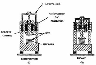
Figure 1.8: Set-up for the SHS/impact forging technique. (a) loading position; (b) position after impact [19].
1.3.4. Hot pressing
One may also synthesize and densify materials simultaneously by initiating combustion-type reactions under high pressure [22-24]. Here, the starting powder mixture is poured into a cylindrical graphite die which is fitted with a grafoil liner. This liner serves both to protect the die and to promote the escape of gases during combustion. The graphite die is equipped with double-acting graphite rams, see figure 1.9. The powder mixture is cold pressed and then inserted into the hot-pressing apparatus. The graphite die is heated by placing a potential across copper plates and allowing the current flow to heat resistively the die. A thermocouple inserted in the die monitors the approximate die temperature at ignition. When ignition occurs the hydraulic rams are compressed to the desired pressure. This pressure is held for approximately 1-2 min i.e. until the die is not anymore red-hot. Via this consolidation technique, products with a final density greater than 99 %TMD can be obtained.
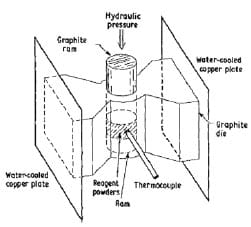
Figure 1.9: Schematic diagram of the combustion synthesis combined with hot-pressing process [25].
1.3.5. Quasi-isostatic pressing
Another possible technique is the combination of combustion synthesis and quasi-isostatic pressing (QIP). A main feature of this method is that, whereas the stress state in explosive and dynamic compaction is dictated by the loading direction and lateral confinement, here almost isostatic conditions are obtained. Real isostatic conditions are only obtained through hot-isostatic pressing machines.
The QIP process is also known as the Ceracon process. The Ceracon process is a patented [26], low-cost process for achieving near-net shape, fully dense parts. This technique makes use of a ceramic particulate material as a pressure-transmitting medium (PTM) instead of gas used in hot-isostatic pressing. This granular medium enables a great degree of freedom in the shapes to be synthesized and it can be pre-heated to ignite the reactive green powder compact, so that an ignition mechanism is no longer needed. The complete Ceracon process is depicted in figure 1.10 and consists of four steps: (1) fabrication of green preform, (2) part heating, grain heating and transfer to the Ceracon die, (3) consolidation, and (4) part removal and grain recycling. In this case, the ignition of the sample is achieved due to the already hot PTM; in other cases, it is necessary to use an electro-match. The thermal properties of the pressure transmitting medium are very favourable to work as an insulator, and thermal stresses, which could produce cracks in reacted/densified compacts, can be minimized. Even so, to reduce thermal stresses the sample is sometimes pre-heated before being inserted into the pressure transmitting medium. The densification occurs in a time scale of seconds, via a plastic deformation of the specimen. The Ceracon forging process does not require the use of shaped dies like the conventional forging process.
Green density of preforms, chemical composition of reactants, time delay between ignition and consolidation, and pressure applied during QIP, are critical parameters in order to optimize the process.
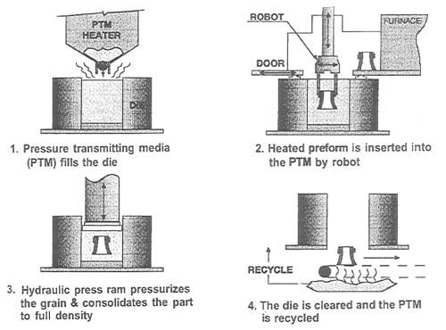
Figure 1.10: Schematic picture of the Ceracon process [10].
In table 1.1 recent papers concerning combustion synthesis and various densification techniques are summarized. The table is limited to TiC-based materials. In column 4 attention is paid to resulting densities in the applied densification steps. Apart from mass diffusion the densities are at least over 90 % of TMD. Only one reference is found regarding functionally graded TiC-based cermets, the topic of experimental study in chapter 2.
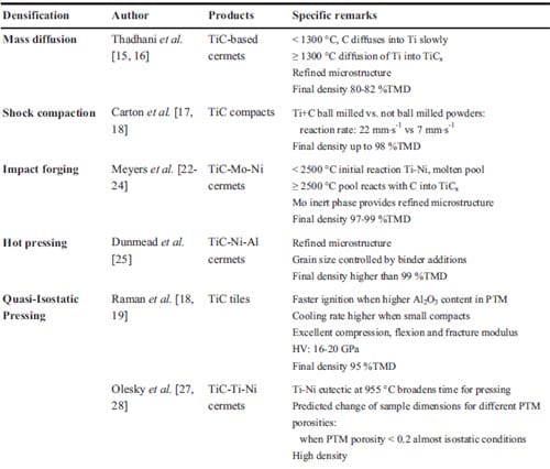
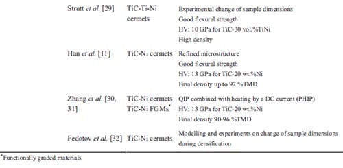
Table 1.1: List of various authors who have used combustion synthesis combined with a densification technique in order to achieve dense materials.
1.4. Numerical simulations of the combustion synthesis process
In the experiments, a densification stage is added to the combustion synthesis reaction to eliminate the remaining porosity in the final product. A time-window has to be anticipated in which application of pressure is effective. It starts after completion of the SHS reaction in order not to quench the reaction and it ends with the solidification of the metallic phase. This timewindow for the quasi-isostatic pressing process can be determined either experimentally or numerically. Experimentally one may determine whether a good product density is obtained, with the disadvantage that several experiments are needed and for each individual configuration of the experiment.
Cooling down after the combustion synthesis reaction has been simulated with the finite element code ABAQUS. ABAQUS is a program for numerical modeling which can solve heat transfer processes together with the effect of mechanical loads. Here an uncoupled thermal problem is considered, i.e. without the influence of the external applied pressure and without thermal stresses generated due to gradients in the system.
To provide conductive heat transfer to the system ABAQUS introduces a gap conductance (k) which considers the effect of two closely adjacent (or contacting) surfaces on the conduction phenomenon. This parameter depends on the two surfaces and materials contacting. High values of gap conductance represent a perfect contact between surfaces and hence a maximum conduction of heat. An accurate estimation of the gap conductance values for the TiB2-based system is hard to achieve. Therefore, simulations have been made considering both high and low values of k. Results have demonstrated that the gap conductance value is only relevant in the first moments of the cooling process (first two or three seconds). Here, results have been obtained considering an ideal contact between surfaces, thus high gap conductance value, which still allows a good approximation of the time-window for densification.
The initial temperature of the reaction products corresponds to the calculated adiabatic reaction temperature, and the SHS reaction itself is not taken into account. Table 1.2 lists the thermal properties used in the simulations. A boundary condition of constant temperature is applied to the die wall. The thermal diffusion coefficient of the isolator is experimentally determined in a series of experiments wh
ere thermocouples are tracking the transfer of heat, released from the SHS reaction, through the isolator, see details in appendix.
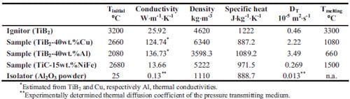
Table 1.2: Initial conditions and melting temperatures of the various materials and their thermal properties conductivity, specific heat and thermal diffusion coefficient.
In chapter 3, the fabrication of TiB2-based cermets for electrical contacts applications will be presented. Sequences of the cooling process in TiB2-40wt.%Cu and TiB2-40wt.%Al cermets are shown here in figure 1.11. One can observe that at 985 seconds the sample is still above 1000 °C, and that the thermal diffusion into the alumina powder is the rate limiting step. Comparing the temperature profile at 0.9 seconds, one can see more or less homogeneous temperature distribution in the copper based cermet, and steep temperature gradients in the aluminium based cermet. This is due to the lower adiabatic reaction temperature for the aluminium based cermet and its higher thermal diffusion coefficient (which controls the time-scale of non-stationary thermal diffusion processes).
In figures 1.12, 1.13, 1.14 and 1.15 the temperature profiles at different locations in sample and ignitor are shown. Figure 1.12 and 1.13 show the variation of temperature at a relatively short time-scale for ignitor and a TiB2-40wt.%Cu or a TiB2-40wt.%Al sample, respectively. Within 10 seconds the temperature difference between ignitor and sample is equilibrated. It indicates that the thermal diffusion in the isolator is becoming the rate limiting step and that one may take advantage of the heat in the ignitor to enhance the time-window of the QIP process. The lattest can be observed in figure 1.13 for a TiB2-40wt.%Al sample. Here the initial sample temperature is 2080 °C (see table 1.2), however the temperature of sample increases to nearly 2400 °C due to the heat transferred from the ignitor.
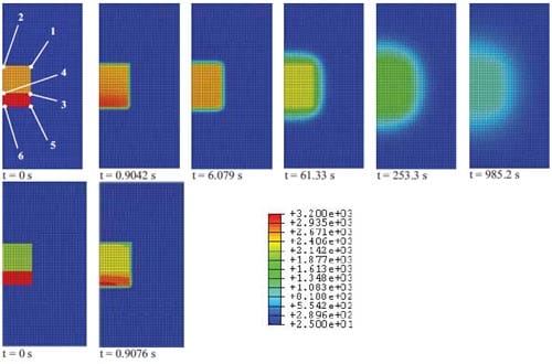
Figure 1.11: Evolution of the temperature profiles (temperature in Celsius and represented by different colours) during the cooling process for sample, ignitor and isolator: TiB2-40wt.%Cu (top), TiB2-40wt.%Al sample (bottom).
In figure 1.14 the melting temperature of copper is indicated as well, and the temperature in the SHS product drops below the melting temperature well after 800 seconds. Therefore, one may extend the experimentally applied time-window of only 100 seconds (to be described in chapter 2 and 3) to 800 seconds. From the numerical simulations of the Al-based cermet an even longer time-window of 1350 seconds is calculated due to the lower melting temperature of aluminium with respect to copper.
In addition, in figure 1.15 the predicted temperature profiles in sample and ignitor for TiC- 15wt.%NiFe cermets are shown. In chapter 2, the fabrication of functionally graded TiC-based cermets is described. Indicating the melting temperature of the NiFe alloy in figure 1.15, one can observe that the temperature in the SHS preform drops below the melting temperature after 400 seconds. The predicted time-window for the system TiC-15wt.%NiFe is rather narrow compared to that for the TiB2-xCu and TiB2-xAl system. In addition, one needs to consider that the real time-window for densification will differ to some extent than the predicted one, due to the fact that the `pressure transmitting medium is being compressed. For this system the time-window can only be slightly increased, as the experimentally applied time-window for densification is rather close to the predited one. Increasing the sample size, or benefit from the heat released by e.g. a larger Ti + 2B ignitor pellet leads to a longer time-window. Another option to enlarge the time-window can be to preheat the PTM.
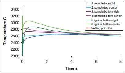
Figure 1.12: Temperature versus time at indicated locations in sample and ignitor for TiB2-40wt.%Cu cermets (see also figure 1.11, frame at t = 0 s).
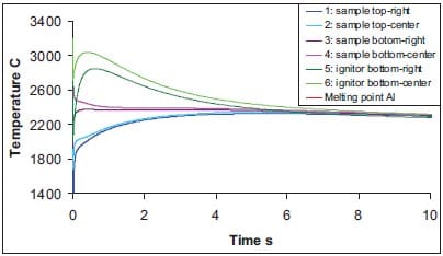
Figure 1.13: Temperature versus time at indicated locations in sample and ignitor for TiB2-40wt.%Al cermets (see also figure 1.11, frame at t = 0 s).
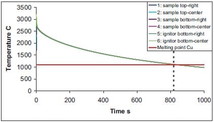
Figure 1.14: Temperature versus time at indicated locations in sample and ignitor for TiB2-40wt.%Cu cermets (see also figure 1.11, frame at t = 0 s), with expanded time-scale and indication of melting temperature of copper.
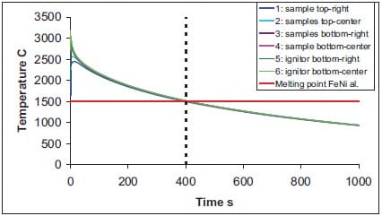
Figure 1.15: Temperature versus time at indicated locations in sample and ignitor for TiC-15wt.%NiFe cermets, with expanded time-scale and indication of melting temperature of copper, see also chapter 2.
1.5. Conclusions
- Self-propagating High-temperature Synthesis is a very exothermic gasless combustion process. It is a cost-effective method for producing high-purity refractory compounds, and advanced ceramics, including functionally gradient composite materials.
- Porosity in the reactant mixture is necessary for both ignition and propagation.
- Due to the exothermicity of the process and the increased density of the reacted material, the final product is largely porous.
- To produce a dense material, a densification or consolidation stage must be applied within seconds after the combustion process.
- Typical densification techniques in particular to obtain dense TiC-based cermets have been reviewed.
- Quasi-isostatic pressing makes use of a granulate medium to transfer pressure to the sample as well as to provide thermal isolation.
- The time-window for densification is determined by the end of the combustion process and the solidification of the final product.
- Understanding of the heat transfer processes in self-sustained high temperature synthesis followed by quasi-isostatic pressing is needed in order to improve the conditions for the consolidation process.
- The time-window for the TiB2 and TiC-based cermets has been numerically simulated with the finite element code ABAQUS, for the experimental set-up to be described in chapter 2 and 3.
- The synthesis of ceramic-metallic materials combining combustion synthesis and quasiisostatic pressing does benefit from the heat released by e.g. a purely Ti + 2B mixture enlarging the time-window for the densification step.
- The time-window for the TiC-15wt.%Ni cermet is rather narrow compared to the TiB2-based cermets, i.e. 400 seconds. An increase of the sample dimensions and/or the ignitor dimensions can lead to enlarge the time-window.
- In a real case, the isolator is also compressed due to the application of pressure. This effect has not been taken into account in the numerical simulations.
1.6. References
- Merzhanov, A.G.: “The Chemistry of Self-propagating High-temperature Synthesis”, J. Mater. Chem., 14 (2004), pp.1779-1786.
- Merzhanov, A.G.: “Combustion Processes that Synthesize Materials”, J. Mater. Process., 56 (1996), pp.222-241.
- Moore J.J., and Feng H.J.: “Combustion Synthesis of Advanced Materials: Classification, Applications and Modeling”, Progress Mater. Sci., 39 (1995), pp.275-316.
- Garcia Ruiz M.: “Combustion Synthesis of Electrical Contact Materials”, TNO PML, Rep. No. PML- 2004-SV012, Dec 2004.
- Moore J.J., and Feng H.J.: “Combustion Sy
nthesis of Advanced Materials: Reaction Parameters”, Progress Mater. Sci., 39 (1995), pp.243-273. - Fisher S.H., and Grubelich M.C.: “Theoretical Energy Released of Thermites, Intermetallics, and Combustible Metals”, Proc. 24th Int. Pyrotech. Sem., Ed. Dillehay D.R., IPSUSA Seminars Inc., Marshall, 1998, pp.231-286.
- Munir Z.A., and Anselmi-Tamburini U.: “Self-propagating Exothermic Reactions: The Synthesis of High- Temperature Materials by Combustion”, Mater. Sci. Rep., 3 (1989), pp.277-365.
- Davies N.: “Pyrotechnics Handbook”, Department of Environmental and Ordnance Systems, Cranfield University, Royal Military College of Science, January 2004.
- Raman R.V., Rele S.V., Poland S., LaSalvia J., Meyers M.A., and Niiler A.R.: “The One-step Synthesis of Titanium-carbide Tiles”, J. Met., 3 (1995), pp.23-25.
- Raman R.V., Army Research Laboratory, Rep. No. ARL-CR-437/438, April 1999.
- Wilson M.A., and Hancox R.J.: ”Pyrotechnic Delays and Thermal Sources”, J. Pyrotech., Ed. Kosanke B., J. Pyrotechnics Inc., Colorado, ISSN 1082-3999, 13 (2001).
- Han J., Zhang X., and Wood J.V., Mater. Sci. Eng., 280A (2000), pp.328-333.
- Munir Z.A., Fu Z.Y., Yuan R.Z., and Yang Z.L.: “Fundamental Study on SHS Preparation of TiB2-Al Composites”, Int. J. SHS, 1 (1992), pp.119-124.
- Namjoshi S.A., and Thadhani N.N., Metall. Mater. Trans. B, 31B (2000), pp.307-316.
- Lee J-H, and Thadhani N.N., J. Mater. Res., 13(11) (1998), pp.3160-3173.
- Thadhani N.N., and Lee J-H, Proc. Ceram. Eng. Sci., sep-oct 1995, pp.1151-1156.
- Carton E.P., Doctoral Thesis, Delft University of Technology, February 1998.
- Carton E.P., Stuivinga M., and Boluijt A.: “TiC by SHS and Dynamic Compaction”, AIP Conf. Proc., Ed.
Furnish M.D., Horie Y. and Thadhani N.N., American Institute of Physics, ISBN 0-7354-0068-7, 620 (2001), pp.1127-1130.
- LaSalvia J.C., Meyers M.A., and Kim D.K., J. Mater. Syn. Process., 1(2) (1994), p.255.
- Niiler L.J., Kecskes T., Kottke P.H., Netherwood, J.R., and Benck R.F., Ballistic Research Laboratory, Rep. No BRL-TR-2951, Aberdeen Proving Ground, MD, December 1988.
- Toth L.E., Transition Metal Carbides and Nitrides, Ed. Margrave J.L., Academic Press, New York, 1971, pp.169-176.
- Meyers M.A., and LaSalvia J.C., Int. J. SHS, 4(1) (1995), pp.43-57.
- LaSalvia J.C, Kim D.K., and Meyers M.A, Mater. Sci. Eng., A206 (1996), pp.71-80.
- LaSalvia J.C, Kim D.K., and Meyers M.A, Mater. Sci. Eng., A206 (1996), p.139.
- Dunmead S.D., Munir Z.A., Holt J.B., and Kingman D.D., J. Mater. Sci., 26 (1991), pp.2410-2416.
- US Patent, no. 1361401, 24 September 1985.
- Olesvky E.A., Kristofetz E., Uzoigwe C., and Meyers M.A., Metal Powder Industries Federation, 3 (1997) pp.43-49.
- Olevsky E.A., Strutt E.R., and Meyers M.A.. J. Mater. Process. Tech., 121 (2002), pp.157-166.
- Strutt E.R., Olevsky E.A., and Meyers M.A.: “Resilient Composites for Armor Applications”, Army Research Office, Rep. No. DAAH04-95-1-0236, February 2001.
- Zhang X., He X., Han J., Qu W., and Kvalin V.L.: “Combustion Synthesis and Densification of Largescale TiC-xNi Cermets”, Mater. Lett., 56 (2002), pp.183-187.
- Zhang X., He X., Han J., Qu W.,and Kvalin V.L.: “Combustion Synthesis and Thermal Stress Analysis of TiC-Ni Functionally Graded Materials”, J. of Mater. Syn. Process., 8(1) (2000), pp.29-34.
- Fedotov A.F., and Amosov A.P.: “Model of Quasi-isostatic Hot Pressing of SHS Products in the System Titanium-carbon-nickel”, Powder Metall. Metal Ceram., 41 (2002), pp.7-12.
Appendix – Determination of the thermal diffusion coefficient of the pressure transmitting medium
Theoretical model
The thermal diffusivity is defined as a measure of the rate at which a temperature disturbance at one point travels to another point within a body. It is expressed by the relationship:
where λ is the coefficient of thermal conductivity, ρ is the density, and Cp is the specific heat at constant pressure. The thermal diffusivity is, therefore, the ratio of heat conducted through the material to the heat stored per unit volume. A large thermal diffusivity leads to fast propagation of heat into the material. If the thermal diffusivity is small it indicates that a large part of the heat is absorbed by the material and only a small portion is conducted through. Some typical values of thermal diffusivity are listed in table 1.
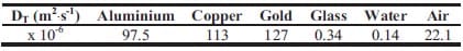
Table 1: Examples of thermal diffusion coefficient values [1-3].
In order to determine the thermal diffusion coefficient for a pressure transmitting media (PTM), the SHS specimen is assimilated as an instantaneous point source of heat, that is to say, a finite quantity of heat is instantaneously liberated at a given point and time in an infinitely large surrounding media. The idea of the instantaneous point source of heat has proved most useful in the theory of conduction of heat [4]. The general equation of conduction of heat,
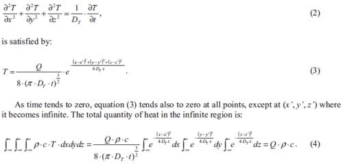
Thus the solution (3) can be interpreted as the temperature in an infinite solid due to a quantity of heat Q·ρ·c instantaneously generated at t = 0 at a point (x’, y’, z’). This solution is the temperature due to an instantaneous point source of strength Q at (x’, y’, z’) and t = 0.
It can be noted that the temperature at a point distant r from the source has its maximum value at t is r2/(6·DT) . This expression will be used in the experimental part to determine the thermal diffusion coefficient of the PTM.
The next step is to find a solution of equation (2) as the limit of a case in which a finite quantity of heat is liberated over a vanishingly small volume i.e. the idealization of the SHS/QIP process in which heat of the reactants is released fast but slowly dissipated into the PTM. Supposing this volume is taken as a sphere of radius a, and considering the case of an infinite medium in which the initial temperature is T0 in the sphere and zero in the region r > a. Making u = T·r, the equations for u are:
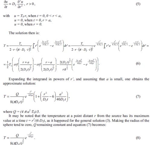
Experimental procedure
The initial setup proposed to measure the temperature at different locations in the PTM, is shown in figure 1. The vessel used to contain the PTM is a PVC tube with an inner diameter of 150 mm, a thickness of 7 mm, and a height of and 200 mm. Three K-type thermocouples are placed at different distances above the sample. Thermocouples T1, T2 and T3 are located at distances 50, 60 and 70 mm far from the SHS compact, respectively. Eventually, for the last two experiments, the distances are changed to 10, 20 and 30 mm far from the SHS pellet for T1, T2 and T3 respectively.
Experiments are performed using as a pressure transmitting media (PTM) a powder mixture of alumina (< 45 µm, Bassermann Minerals GmbH, Germany) and 5 vol.% graphite (<45 µm, Sigma Aldrich Chemie B.V., The Netherlands). The SHS sample consists on an exothermic powder mixture, namely titanium and graphite powder together with an extra addition of Ni al. powder working as an inert phase. High-purity (99.5 %) powders of carbon (Sigma Aldrich Chemie B.V., The Netherlands) with an average particle size of 10 µm, titanium (Gimex Technische keramiek B.V, The Netherlands)
and an NiFe alloy with 50 wt.% Fe and 50 wt.% Ni (H.C. Starck, Germany) are used in the experiments. Both the Ti and the NiFe powder have a particle size of 45 µm (-325 mesh). Cylindrical graded pellets with a diameter of 21 mm and thickness of about 10 mm are obtained by stacking 4 layers of Ti + C+ x wt.%NiFe alloy, with x increasing from 5 to 30 followed by uniaxially pressing in a steel die.
To ensure the ignition of the Ti +C + 15wt.%Ni pellet, a second pellet made from a more exothermic powder mixture i.e. Ti + 2B is placed below the first one. The green density of both specimens is determined for all the experiments. After placing samples and thermocouples inside the PTM, its density is estimated by weighting the mass of PTM needed to fill up completely the container. After ignition the heat is slowly dissipated into the PTM creating a gradient in temperature as registered by the thermocouples.
The thermocouples are connected to a data logger which registers the temperature evolution and transfers the data to a computer. The experiment is finalized when the temperature profile registered by the thermocouples shows a clear decrease. A good alignment of the thermocouples is considered as one of the most critical parameters to obtain reliable measurements.
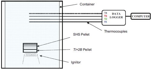
Figure 1: Scheme for the final setup to determine the thermal diffusion coefficient of the pressure transmitting medium (PTM). The ignitor, ignitor pellet and SHS pellet are placed inside the PVC tube containing the PTM, after that the thermocouples are aligned at various distances from the SHS sample.
Results
The curves depicted in figure 2 represent the evolution of temperature in time for tests SHSTH6 at three fixed points far from the heat source 50, 60 and 70 mm. All curves are characterized by two different tendencies: firstly an increasing branch is observed achieving a maximum value of temperature followed, after the maximum, by a decreasing branch indicating the cooling stage. The combustion of the sample or pellet begins a few seconds after the data acquisition did. One can observe that the alignment of the thermocouples is correct according to their distance to the SHS pellet.
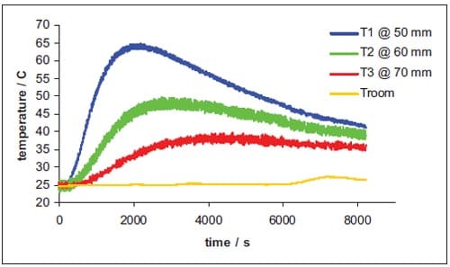
Figure 2: Evolution of the temperature for three thermocouples situated at 50, 60 and 70 mm far away from the SHS specimen in the SHS/TH6 test.
Figure 3 shows the evolution of temperature in time for tests SHSTH8 at three fixed points far from the heat source 10, 20 and 30 mm. Again curves are characterized by two different tendencies and the alignment of the thermocouples seems to be correct.
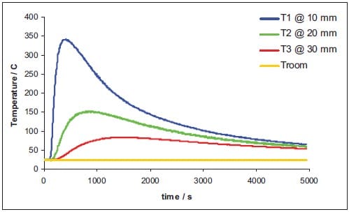
Figure 3: Evolution of the temperature for three thermocouples situated at 10, 20 and 30 mm far away from the SHS specimen in the SHS/TH8 test.
If now one plots t versus r2 at the maximum of each temperature profile, with the slope being 1/(6·DT), the thermal diffusion coefficient of the PTM can be estimated. The values of DT obtained in the various experiments, are summarized in table 2. It has also to be remarked that in the last two experiments, SHSTH7 and SHSTH8, the thermocouples are placed at distances closer to the SHS pellets than for the first six experiments. Table 2 gives as well averaged values of DT for the first 6 experiments and for the total.
The diffusion coefficient for alumina is close to 7.2 10-6 m2·s-1 (99.7 % purity), while the diffusion coefficient for carbon is close to 3.06 10-6 m2·s-1. The average DTL measured is always below either of the two values as they are largely determining the thermal properties of the PTM.
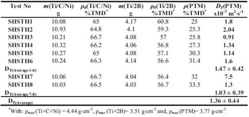
Table 1: Empirically estimated values of the thermal diffusion coefficient (DT). Here m and p0 refer to the mass and green density of the specimen, respectively
References
- https://www.educaplus.org/sp2002/index_sp.php
- https://www.mhtl.uwaterloo.ca/old/onlinetools/airprop/airprop.html
- Ceramic and Glasses, Engineered Materials Handbook , 4, Ed. ASM International, 1991.
- Carlsaw H.S. and Jaeger J.C., Conduction of heat in solids, 2nd Edition, pp.255-260.
Chapter Two
Functionally Graded TiC-based Cermets1
Experimental results on the preparation of functionally graded TiC-based cermets obtained by combustion synthesis followed by quasi-isostatic pressing in a granulate medium are presented in this chapter.
Pellets of TiC-Ni graded cermets are produced by stacking layers of Ti and C powder mixtures in which the content of a NiFe alloy (50 wt.% Ni and 50 wt.% Fe) is varied from 5 up to 30 wt.%. X-ray diffraction shows that the NiFe alloy does not take part in the reaction, avoiding the presence of intermetallics. In this way the good properties of this material i.e. low thermal expansion are preserved. Local pressure values inside the pressure transmitting medium have been measured using thin pressure sensor films that are normally used for flat metal surfaces in local contact (Pressurex® films). Measurements performed with horizontally and vertically placed sensors in direct contact with the pressure transmitting medium shown significant lower pressure values than the applied ones. Moreover, the pressure distribution is homogeneous for the horizontally placed sensors. However the vertically placed sensors do not yield good results. This indicates that the pressure is more of an uniaxial nature. Scanning electron microscopy results show that the porosity in these graded materials is still high with pores increasing in size towards the side with the highest ceramic fraction. When comparing the experimental results to densities obtained by various authors, there is certainly a potential to decrease porosity below 5 to 10 %. The pressure distribution in quasi-isostatic pressing of the TiC-based cermets is not the real issue in obtaining high density cermets. A good understanding of the thermal processes in self-sustained high-temperature synthesis followed by quasi-isostatic pressing is needed in order to improve the consolidation process. It has been described in chapter 1.
A brief introduction into the composite and functionally graded materials is given in paragraph 2.1. The experimental arrangements for production of TiC-based functionally graded materials is described in paragraph 2.2. A discussion of results and conclusions are as well drawn in paragraphs 2.3 and 2.4, respectively.
2.1. Introduction
It is well known that ceramics are useful in high strength and temperature applications; however, they suffer from low toughness. This drawback can be solved combining ceramics with metals of high toughness. TiC-based ceramic-metallic composites (cermets) are promising for industrial applications including high-temperature corrosion resistant material and lightweight armour material. It has been shown that TiC-based cermets possess excellent resistance to wear, corrosion and oxidization. They also have, a low friction coefficient and density [1-3]. Some of these excellent properties depend not only on the major phase percentage (TiC) but as well on the metal phase added, in order to create the final cermet. So far, scientists have incorporated Ni, Cr, Al, Fe, Mo, or Co into a reactant mixture of Ti and C [4-10].
Functionally graded materials
(FGMs) are a new generation of engineering materials which offer layered microstructures consisting of two or more phases with different volume fractions varying gradually in one direction. Modifying the layered microstructure, material properties including strength, toughness, stiffness, optical properties, electrical properties and thermal properties can be tailored. Many industrial applications such as aircraft engines, computer circuit boards, medical implants, armour, and optical devices, can benefit from utilization of the general FGM concept.
The synthesis of functionally graded materials has been successfully demonstrated through a variety of methods, e.g. thermal spray, powder metallurgy, physical and chemical vapour deposition, and combustion synthesis [11, 12]. Recently, the rapid development of SHS has provided a good option for the fabrication of net shape or near-net shape FGM components. When FGMs are fabricated for high temperature or armour applications, TiC is usually chosen as the ceramic phase. Additions of a ductile phase avoid macrocracking which is the main difficulty encountered in the densification of TiC due to residual thermal stresses [13].
In this respect, various researchers [14, 15] have studied the fabrication of FGMs using the Ti-C-Cu and Ti-C-Ni systems. By combining combustion synthesis and quasi-isostatic pressing, Zhang et al. [14] have investigated the fabrication of TiC-Ni FGMs and measured some physical and mechanical properties, and Sata et al. and Ma et al. [16, 17] have obtained near-fully dense TiB2-Cu and TiC-Ni FGMs.
In this chapter, not only the fabrication of TiC-based FGMs by the SHS/QIP technique has been studied. In addition, the pressure distribution in the pressure transmitting medium has been estimated.
2.2. Experimental arrangements
Sample preparation
Figure 2.1 shows a schematic picture of the steps followed in the gasless combustion process to produce the cermets for the various applications. In addition, this combustion process is carried out in a thermal insulating medium, which can transfer the pressure for densification of the reacted and hot material, see figure 2.2.
High-purity (99.5 %) powders of carbon (Sigma Aldrich Chemie B.V., The Netherlands) with an average particle size of 10 µm, titanium (Gimex Technische keramiek B.V, The Netherlands) and an NiFe alloy with 50 wt.% Fe and 50 wt.% Ni (H.C. Starck, Germany) were used in the experiments. Both the Ti and the NiFe powder had a particle size < 44 µm (-325 mesh). Ti, C and NiFe powders were dry mixed in order to obtain stoichiometric mixtures of Ti, C, and x wt.%NiFe alloy, with x = 5, 10, 20, and 30 respectively. Cylindrical graded pellets with a diameter of 21 mm and thickness of about 10 mm are obtained in this case by stacking 4 layers of Ti + C + x wt.% NiFe-alloy, with x increasing from 5 to 30 followed by uniaxially pressing in a steel die. The applied pressure was 150 MPa resulting in a green density of 65 % of the theoretical density (TMD) with respect to the x = 15 composition.
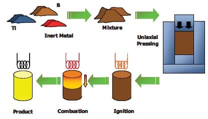
Figure 2.1: Scheme of the basic steps, the combustion synthesis process to synthesize materials comprises.
Synthesis and densification process
Figure 2.2 shows a scheme of the steel die used for the combustion synthesis and quasi-isostatic pressing. The green pellet is placed in the loosely packed pressure transmitting medium (PTM), with the side with the lowest metal content (5 vol.%) positioned at the bottom, in order to facilitate the ignition. The sample is remotely ignited by a resistance wire (Kanthal) through a layer of loose Ti + 2B powder (in stoichiometric ratio) and/or, in some of the cases, an ignitor pellet consisting of Ti + 2B powder (low density pellet) positioned on the bottom. This is a variation of the Raman’s technique [10], in which the hot PTM is poured on the green, which ignites the green in a few seconds. After 2-3 seconds a current of 4.5 A ignites the ignitor pellet which does the equivalent with the green pellet. The ejection of some of the PTM out of the die is a clear indication that the SHS reaction is taking place.
Experimentally it is observed that the SHS process is finished 3 to 6 seconds after ignition of the ignitor pellet. The duration of the SHS reaction is determined from a separate experiment in the same configuration, but without applying pressure. This is done by measuring the average combustion wave velocity using two thermocouples type K, one placed on the bottom and one on the top of the graded pellet, that indicate the passage of the combustion wave.
A pressure between 150 and 400 MPa is then applied 5 to 8 seconds after ignition, for a total duration of 100 seconds. Due to loading and unloading the press, maximum pressure is maintained for 50 seconds. After consolidation, the sample remains inside the die for slow cooling, avoiding cracking due to thermal stresses.
Figure 2.2: Schematic drawing of the configuration for combustion synthesis followed by quasi-isostatic pressing.
Pressure transmitting medium
The material used as a PTM is a mixture of high purity alumina powder (Bassermann Minerals GmbH, Germany) and 5 vol.% graphite powder (Sigma Aldrich Chemie B.V., The Netherlands). The average particle size of the alumina and carbon is 45 µm for most of the experiments, while in some cases alumina with a particle size of 300 µm is used. Pressure distribution results are obtained by small sensor films, denominated Pressurex® (Sensor Products Inc., US), having a thickness of 0.2 mm, that are cut into strips of 10 mm x 5 mm. This type of sensor film is consists of a thin layer with inter-filled hollow spheres, backed by a developer layer. When the spheres break under the influence of an applied force, the underlaying developer layer becomes developed, which produces a local color change. In this way pressure distributions can be measured locally (maximum values).
In general, Pressurex® films are used to reveal the distribution and magnitude of pressure between contacting or impacting surfaces. During these experiments, Pressurex® films are used to measure pressure in a granulate medium, where contact point of the grains of the PTM might affect the result. Therefore also some experiments are effectuated by covering the sensor film at both sides with a stainless steel metal foil (0.05 mm), in order to simulate flat surfaces.
Pressure films are placed inside the PTM in different zones, in a horizontal and vertical direction, see figure 2.3. Two pressure values are applied: 55 and 105 MPa respectively. For that purpose three types of pressure films are used: low (L), medium (M) and high (H) having a pressure range of 2.4-9.7, 9.7-49, and 49-120 MPa respectively. The pressures indicated by the film can be read from color calibration tables with an accuracy of 15 % as is specified by the producer.
Figure 2.3: Placement of the sensor films inside the pressure transmitting medium. The dotted outline represents the position the SHS sample should occupy during the pressing stage.
2.3. Results and discussion
Pressure measurements
Figure 2.4 shows four examples of pressure film measurements. The duration of the measurement amounts to 30 s, which is well above the 10 s required for reading the calibration tables. In general, the colour intensity for the low applied pressure (55 MPa) is more intense than for the higher one (105 MPa). This has to do with the fact that in the former case the measured
pressure is close to the measurement range of the sensor type (medium), while it is more in the middle of this range of the respective sensor type (high) for the latter. The accuracy in the applied pressure Pa amounts to ± 5 MPa, while the measurement accuracy of the films is ± 6 MPa.
Table 2.1 summarizes the various experiments performed with pressure films. After application of pressure, vertically placed films appear usually bended. This effect may be avoided by decreasing their length. However, the vertical films (3A and 4A in figure 2.4) register significantly lower pressure values (about 50 %) than horizontal films. Horizontal films (2, 3B and 4B in figure 2.4) with the exception of sensor 1, present comparative colors, indicating that the pressure is quasi-homogeneous, although of a quasi-uniaxial nature. Even so, the measured values of pressure are always lower than the applied ones. Sensor 1 which is near the bottom of the die shows appreciably low values, being in between the values registered for the vertically and the other horizontally placed sensors.
In test no. 3 the die walls are coated with a layer of lubricant in order to avoid friction between the PTM particles and the die walls. If one compares test no. 1 with no. 3, friction appears to have no influence into the transfer of pressure to the films. This is consistent with the quasi-homogeneous results found for sensor 2 positioned in the upper side of the die, and sensors 3B and 4B positioned in the middle of the die. However, measurements performed with protective metal films, represented in table 2.1 by test no. 8 to 11, show significant low values, which add some doubt concerning the measurements of the unprotected films. Probably some grains in the PTM have induced high local pressure values, making it more difficult to interpret the results.
Figure 2.4: Sensor films after removal from the PTM. Left: sensors type high (49-120 MPa) after pressing at 105 MPa (45 µm alumina); Right: sensors type medium (9.7-49 MPa) after pressing at 55 MPa (300 µm alumina).
Table 2.1: Measured pressure values (Pexp) with various Pressurex® sensor films using applied pressures (Pa) of 55 and 105 MPa respectively. The indexes h and v indicate whether films are placed horizontally or vertically, respectively. The Al2O3 particle size used for the various PTM mixtures is also indicated.
Functionally graded samples
For two of the specimens with a thickness of 10 mm, an average combustion front velocity of 1.67 ± 0.7 mm·s-1 is measured. Therefore, it is estimated that the SHS reaction through the pellet will be finished in about 6 seconds.
X-ray diffraction analysis is performed on similar specimens having a NiFe content of 5 wt.%, see figure 2.5. In the X-ray diffraction pattern mainly peaks belonging to the TiC spectrum are visible, since apparently the metal content is too low to be discerned. When the spectra are studied in detail, peaks of the metallic phase NiFe appear weakly. The absence of intermetallic peaks is an indication that the NiFe phase has not reacted with the TiC. The presence of Al2O3 and C may be due to some rests of the PTM powder adhered to the sample. In the case of C, it can also indicate that C that did not react completely.
Figure 2.6 shows a SEM image of the remaining porosity in a TiC-based functionally graded compact densified at 400 MPa. A gradient in porosity varying from the top (5 wt.% NiFe) to the bottom (30 wt.% NiFe) is observed. The area containing the highest ceramic content presents the largest pores. The global final density is measured using the Archimedes technique obtaining values no larger than 70 % TMD (with respect to the 15 wt.% NiFe composition). It is clear that the material, especially regions with the highest ceramic content, are still too porous, and the densification process has to be improved. These results can help to improve and tailor the densification stage. Figure 2.7 represents the evolution of the temperature of a generic SHS sample inside the PTM. The dashed line represents the loading sequence of the QIP process. The densification stage must conclude before the temperature of the SHS product drops below the melting temperature of the inert metallic phase i.e. tc ≤ tmax in figure 2.7. In chapter 1, simulations of the heat transfer of the SHS product into the PTM have been presented and a theoretical time-window has been estimated. Given these simulations, although carried out later than the actual experiments, there is a possibility to extend the time-window for densification. In chapter 3, the same experimental time-window (100 s) is used resulting in more dense materials. The difference between the materials is the hardness of the final product. This property has not been taken into account in the numerical simulations.
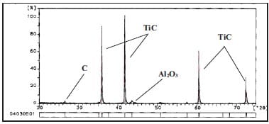
Figure 2.5: X-ray diffraction pattern of a TiC-based functionally graded cermet (layer with a 5 wt.% NiFe).
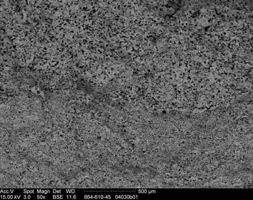
Figure 2.6: Scanning electron-micrograph of the cross section of a graded TiC-NiFe cermet consisting of 4 layers of varying metal content (from top to bottom 5 to 30 wt.%).
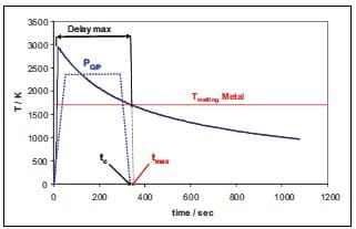
Figure 2.7: Schematic representation of the temperature profile of a generic SHS sample and loading sequence of the QIP densification process. The maximum time-window tmax is determined by the melting temperature of the inert metal. The experimental time-window tc includes loading, holding of pressure and unloading
2.4. Conclusions
- Functionally graded TiC-NiFe-alloy cermets have been fabricated by combustion synthesis followed by quasi-isostatic pressing in a die filled with a granulate medium (PTM).
- The functionally graded material consists of four stacked layers of increasing metal content (5-30 wt.%).
- The X-ray diffraction measurements show that the NiFe alloy does not react with Ti and/or C, avoiding the presence of intermetallics which could weaken the microstructure.
- Local pressure values inside the PTM have been measured using thin pressure sensor films (Pressurex® films).
- The pressure is homogeneously transferred to the horizontally placed sensors, but rather less in the case of vertical sensors. The pressure is more of an uniaxial nature.
- The porosity in these functionally graded cermets is still high especially in regions with the highest ceramic content. According to experimental results obtained by various authors, there is certainly a potential to decrease porosity below 5 to 10 %.
- The pressure distribution in quasi-isostatic pressing of the TiC-based cermets is not the real issue in obtaining high density cermets.
2.5. References
- Gee M.G., Reece M.J., and Roebuck B., J. Hard Mater., 3(2) (1992), p.119.
- Kang S., Powder Met., 40(2) (1997), p.139.
- LaSalvia J.C., Kim D.K., and Meyers M.A., Mater. Sci. Eng., A206 (1996), p.139.
- Saidi A., Chryssanthou A., Wood J.V., and Kellie J.L.F., J. Mater. Sci., 29 (1994), p.4993.
- Quncheng Fan, Huyifen Chai, Zhihao Jin, J. Mater. Sci., 32 (1997), p.4319.
- Dunmead S.D., Ready D.W., Semler C.E., and Holt J.B., J. Am. Ceram. Soc., 72 (1989), p.2318.
- LaSalvia J.C., Kim D.K., Lipsett R.A., and Meyers M.A., Metall. Mat
er. Trans., A 26 (1995), pp.3001. - LaSalvia J.C., and Meyers M.A., Metall. Mater. Trans., A 26 (1995), pp.3011.
- Choi Y., Lee J.K., and Mullins M.E., J. Mater. Sci., 32 (1997), pp.1717-1724.
- Raman R.V., Rele S.V., Poland S., LaSalvia J., Meyers M.A., and Niiler A.R.: “The One-step Synthesis of Titanium-carbide Tiles”, J. Met., 3 (1995), pp.23-25.
- Shon I-J, and Munir Z.A.: “Synthesis of TiC, TiC-Cu Composites, and TiC-Cu Functionally Graded Materials by Electrothermal Combustion”, J. Am. Ceram. Soc., 81(12) (1998), pp.3243-3248.
- Holt J.B.: “Self-Propagating, High-Temperature Synthesis”, Engineered Materials Handbook, Vol.4: Ceramics and Glasses, Ed. ASM International, pp.227-231.
- LaSalvia J.C., Meyers M.A., and Kim D.K., J. Mater. Syn. Process., 1(2) (1994), p.255.
- Zhang X., Han J., Du S., and Wood J.V.: “Microstrure and Mechanical Properties of TiC-Ni Functionally Graded Materials by Simultaneous Combustion Synthesis and Compaction”, J. Mater. Sci., 35 (2000), pp.1925-1930.
- Zhang X., He X., Han J., Qu W.,and Kvalin V.L.: “Combustion Synthesis and Thermal Stress Analysis of TiC-Ni Functionally Graded Materials”, J. of Mater. Syn. Process., 8(1) (2000), pp.29-34
- Sata N., Sanada N., Hirano T., and Niino M.: “Fabrication of a Functionally Gradient Material by using a Self-Propagating Reaction Process”, Combustion and Plasma Synthesis of High Temperature Materials, Ed. Munir Z.A. and Holt J.B., VCH, New York, 1990, p.195.
- Ma X., Tabihata K., and Miyamoto Y., Ceram. Engineer. Sci. Process., 13 (1992), p.356.
Chapter Three
TiB2 – based Cermets for Electrical Contacts Applications1
TiB2-based cermets for electrical contact applications are prepared by combustion synthesis followed by a pressing stage in a granulate medium. Due to the exothermicity of the process and the increased density of the reacted material, the final product usually possesses by a large remaining porosity (typically 50 %). In order to produce dense ceramics or cermets, a subsequent densification step is performed within seconds after the combustion process and when the temperature of the reacted material is still above the ductile-to-brittle transition temperature of the ceramic phase and/or the melting temperature of the inert metallic phase, which acts as a binder.
A selection based on electrical conductivity calculations of candidate materials is made first. TiB2 cermets with 40 wt.% Cu or 30-40 wt.% Al have been made. The low remaining porosity in the TiB2-Al material is attributed to the relatively large volume of the aluminium diluent and a low melting point, when compared to the copper diluent. The combustion temperature of the copper based cermet is slightly above the copper boiling temperature, increasing internal pressure. Electrical and hardness measurements confirm that combustion synthesis followed by quasi-isostatic pressing can successfully lead to electrical contact application materials comparable to silver metal oxides and silver refractory metals. Finally, it is observed that the volume content of the metallic binder plays an important role to achieve predicted and high values of electrical conductivity.
In paragraph 3.1 an introduction is given into the arcing phenomenon and different arcing contact materials. A selection of promising arcing contact materials to be made by combustion synthesis is described in paragraph 3.2 and based on required properties and modelling. Preparation of the TiB2-based cermets and their relevant properties in electrical contact applications are described in paragraphs 3.3 and 3.4. Measured properties will be discussed and final conclusions will be drawn in paragraph 3.5
3.1. Introduction
Electrical switches are designed to pass electric current or signals across a separable interface without introducing disturbances, noise, etc. Electrical energy will be dissipated as it encounters electrical resistance. Essentially, there exist two types of electrical resistance:
- Bulk resistance: is the resistance of the material along the path of the current. Bulk resistance is dependent on the electrical resistivity of the contact material and the shape of the contact.
- Contact resistance: consists of a variable resistance at the interface between the two contact surfaces. The contact resistance is dependent upon the contact force between the two surfaces in contact.
A close look at the contact interface reveals that all surfaces in general posses some roughness. The contact points or contact spots are called asperities. The total sum of these contact areas, being the true area of contact, is typically much smaller than the apparent surface area of the contact interface. The number of contact spots depends on the applied contact force and the hardness of the contact material. The maximum contact area for clean surfaces is given by the expression [1]:
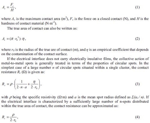
The resistance of a mechanical contact with a clean surface i.e. η = 1, can be calculated from equations (1), (2) and (4):
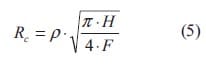
The contact resistance may be composed of a constriction resistance and a film resistance, see figure 3.1. The first one appears because of the passing of the electrical current through the asperities thereby forming thin layers of oxides or contamination on the contact. Oxides present higher resistivity than pure materials, acting as an obstacle for the current to travel through the film.
As the normal force increases the Hertz stress, i.e. the highly localized stress created by the contact, will increase. This decreases the constriction resistance since there are now more and larger paths for the signal to travel through. Since the contacting surfaces are wider, the current can more easily pass through any film that might exist. Therefore, the film resistance decreases as well.
In figure 3.2, the relationship between contact force and contact resistance is represented. It is noticeable that at very high contact forces, most of the total resistance of the contact is formed by the bulk resistance.
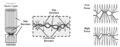
Figure 3.1: Representation of the bulk and contact resistance, the latter detached in its two components (left); effect of increasing the contact force, which allows the current to travel much easily (right).
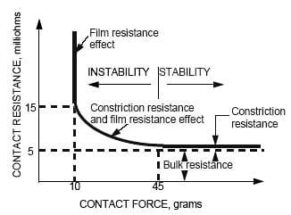
Figure 3.2: Representation of the contact resistance as a function of the contact force.
3.1.1. Arcing
Arcing is a phenomenon by which a current can travel across a gap between electrically charged surfaces such as the two contact surfaces on a separated electrical connector, see detail in figure 3.3. Arcing can occur upon both the opening and the closing of a contact interface.
An electrical switch allows passage of a current across the contact interface when it is in a closed position. Due to a contact resistance there exists a voltage across the contact interface. When a switch is opened, the current stops flowing but at the same time a large voltage difference can be maintained across the gap when the switch is in open position. This voltage can induce an arc across the gap between the contacts surfaces, in case of electrical breakdown.

Figure 3.3: Schematic picture of an arcing contact; plasma columns, metal vapours and electrode wear are characteristics of arcing.
Arcs can only be initiated when the electrical potential between two contacts exceeds the minimum arc voltage, and the available current in the circuit exceeds the minimum arc current. These values depend on many factors such as the contact interface material, distance between contacts and the medium between contacts.
In the case of closing arcs, the minimum arc voltage will decrease when the two contact surfaces approach each other. If the source voltage is too small, no arc will form, and the current will only flow when the contacts are touching each other. Arcing begins when electrons jump across the contact gap from the anode to the cathode.
Opening arcs are initiated in a different way. Any two surfaces in contact touch each other only at their asperities. There exists a contact resistance as the current passes through these small numbers of paths across the interfaces. As the contacting surfaces begin to separate, the asperities decrease in size and number. This forces a great amount of current to flow through each asperity and increase electrical resistance. Resistance heating eventually will cause the last few paths to melt, resulting in a current carrying a molten metal bridge between the contacts. The bridge will vaporize at temperatures high enough to release electrons, initiating the arc.
Arcing has several negatives consequences that must be considered [1]:
- Metal transfer. During an arc, electrons will pass from the cathode to anode. In turn, the anode may release positive ions from its surface, which travel to the cathode. The latter case would result in transfer of metal from the anode to cathode. This is usually the case, but in some circumstances, the direction of the metal may be reversed. In AC circuits, the polarity of the contacts continuously changes, but the instantaneous direction of transfer depends on which of the contacts happened in the moment of the interruption. The net transfer will be approximately zero.
- Welding. When the contacts are closed, the heat created by the arcing may cause the contact surfaces to melt and consequently to weld together. If the opening force is sufficient, the weld will be ruptured when the contacts are opened, resulting in some mechanical damage of the contacts surfaces. Silver tin oxide, silver cadmium oxide, and silver cadmium composites have high melting temperatures and are less likely to weld than pure silver contact surfaces
- Erosion. The energy of the impact can damage the contact surfaces of the switch. Over many cycles, small fatigue cracks will appear and grow at the interface. The total erosion of the contact interface is a combination of material transfer, material vaporization, and mechanical damage from impact, fatigue, and separation of welded contact surfaces. The amount of wear that occurs in each contact cycle depends on many factors including current level, arcing time, size of the contact gap, gasses present in the gap, opening and closing velocity, contact stress, number of bounces on closure, movement of the arc on the contact surfaces, contact size, shape, and material.
- Corrosion. The high energy of arcing will result in formation of corrosion products such as oxides, nitrides, chlorides, carbides and sulphides on the surfaces of the contacts. This will cause the electrical resistance on the contacts interface to increase over time.
- Contact bounce. A single contact closure may result in multiple impacts and arcs. In order to reduce the wear of the contacts it is necessary to minimize the number and height of the bounces. This can be achieved by reducing the impact velocity, decreasing the inertia of the contacts, increasing the impact force, and increasing the impact absorption. Bouncing can be better controlled by using contacts with low inertia and high contact force, and by using contact material that are more resistant to arc formation and wear.
3.1.2. Categories of arcing contact materials
Arcing contact applications cover very wide range of applications in terms of the current level to be switched, electrical load, voltage, current (AC or DC), ambient conditions, and mechanical opening, closing force as well as velocity.
Silver is characterized by high electrical and thermal conductivity; this fact makes it ideal for handling high electrical currents. “Fine silver” possesses more than 99.9 % of purity. It has the highest electrical conductivity of all the electrical contacts materials. However, it has only moderate wear resistance, with a hardness of 75-200 HV (Hardness Vickers), similar to soft gold.
Silver based composite materials such as silver-nickel and silver-metal oxides offer significantly improved resistance to arc erosion, as compared to fine silver. Silver composites are usually produced through powder metallurgy processes, since the constituents are not mutually soluble and cannot be alloyed. These include silver metal oxides (silver cadmium oxide, silver tin oxide, silver indium oxide), silver graphite, silver molybdenum, and silver nickel. Silver composites and silver metal oxides are used in higher current, higher voltage switches where there exits a potential for severe damage caused by arcing. They resist better to arc erosion than fine silver. Their higher melting temperatures make them also more resistant to contact welding.
Because of the large variety of silver-based compounds utilized for arcing contacts applications they are grouped into categories. Arcing contacts materials are usually divided into six different categories summarized in table 3.1.
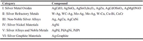
Table 3.1: Categories of arcing contact materials [1].
Silver metal oxides (category I)
Silver metal oxides represent not only the most popular and important category of arcing contact materials but also the most dynamic in terms of research and development. They are composites consisting of a silver matrix and a dispersion of fine particulates of single or multiple oxides.
Their properties can vary widely depending on processing and dopants. In general, silver metal oxides have hardness values HV ranging from 0.75 to 1.15 GPa. Their electrical conductivity σ varies from 0.35 to 0.5 x 10⁸ Ω-1·m-1. The parameter p·HV (with p = 1/σ) establishes a connection between the electrical resistance p, the hardness of the material HV on the one hand, and the contact resistance on the other hand, see equation (4). It is used as a design parameter being proportional to the contact resistance. Typical arcing contact materials of category I present values of p·HV varying from 1.7 to 3 x 10⁻⁸ Ω·m·GPa1/2. Contacts of category I usually can carry currents in the range from 1 to 3000 A.
Silver refractory metals (category II)
Silver refractory metals are a special category of arcing contacts materials for high current applications. Recently, silver refractory metals have become one of the preferred contact materials in contactors for switching currents of hundreds of amperes up to several kiloamperes.
Silver refractory metals have relatively high electrical conductivity combined with other desirable features such as low and stable contact resistance and excellent resistance to sticking and welding. These properties are obtained by additions of cadmium oxide, nickel, carbon, magnesium, iron, etc. Their hardness can vary from 1.25 to 2 GPa. Silver refractory materials have electrical conductivity values in the range from 0.23 to 0.32 x 10⁸ Ω-1·m-1</su p>. The parameter ρ·HV can vary from 3.17 to 6.15 x 10⁻⁸ Ω·m·GPa1/2. Composite refractory metals are normally used in medium and high current devices such as circuit breakers and interrupters. Since these materials develop resistance problems during repetitive switching, they are not recommended for lower current unless they are required to switch fault current. As a result, the main application of these materials is for switching current values of about 1000 A or more. At high current, refractory metals offer superior erosion resistance compared with other silver-based alloys, including silver metal oxides.
Silver-nickel materials (category IV)
Silver-nickel materials are a very popular type of contact material used world wide, and especially used in Europe [1]. This type of arcing contacts is used as low voltage circuit breakers. The contact material can be directly welded onto copper substrates, reducing considerably the cost of the contact assembly. However, this fact can be a disadvantage for some applications where the high current level may cause welding of the contacts. Depending on the device and type of load, silver-nickel materials are especially suitable for values of current between 50 and 100 A.
3.2. Selection of the electrical contact materials
Currently, there exists a great interest in the development of new electrical materials for improving the performance of electrical contacts or connectors in high voltage switching applications.
The main requirements for an electrical material include a good electrical conductivity and a high melting point. Silver refractory metals and silver metal oxides posses these characteristics and are ideal for use in high-current applications. They are based on silver and copper powder as starting materials, which are mixed, pressed, sintered, and, in some cases, infiltrated with liquid of Ag or Cu. Unfortunately the processing used to fabricate these materials is the major drawback. It involves multiple processing steps including, conversion of compounds to the desired composition, powder processing and particle size distribution, followed by high temperature sintering to densify, and finally machining of consolidated products. These multiple steps result final products with elevated costs [2, 3].
Combustion synthesis is reported to be a promising technique for the fabrication of composite materials [4-13]. The main disadvantage of this method lies in the high degree of porosity of the final products. This porosity can be reduced by compressing the synthesized product while it remains above its ductile-to-brittle transition temperature. One of the appropriate consolidation techniques is the quasi-isostatic pressing, which combined with combustion synthesis offers a relatively simple processing method to produce dense components [12, 13].
The life and performance of a product are determined, in a large degree, by the material composition used in the manufacturing. Identifying the proper material is one of the most critical decisions in the fabrication process.
In order to determine the best combination of materials to be produced by combustion synthesis, several ceramics and metals ware considered as potential candidates. From the ceramic compounds able to be fabricated by combustion synthesis and showing good electrical properties TiC, WC and TiB2 have been selected. The metallic or binder phase must be a non reactive metal with high electrical conductivity such as Al, Ag or Cu.
Table 3.2 lists typical properties of the candidates selected to match the optimum combination for electrical contact applications. TiB2 presents higher electrical conductivity compared to WC or TiC and an attractive high value of hardness. In addition, this ceramic possesses a good resistance to thermal shock making it an ideal material for working in applications where pulsating energy is involved.
Concerning the feasibility to fabricate cermets via combustion synthesis, table 3.2 lists the adiabatic temperatures for pure ceramics. As mentioned in chapter 2, the adiabatic reaction temperature and hence the combustion temperature, of a combination of ceramic and diluent will be lower than those listed in table 3.2. Taking into account the experimentally determined limit of 1800 K for a gasless reaction to be self-sustained, the reaction to obtain WC at room temperature will not proceed spontaneously after ignition. In order to fabricate WC by combustion synthesis an additional source of energy will be needed; this fact will make its production rather costly.
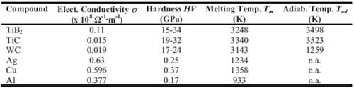
Table 3.2: Properties of ceramic and metallic phases selected as candidates in the synthesis of cermets for electrical contact applications via SHS, including melting and adiabatic reaction temperature, Tm and Tad, respectively [14].
With regard to the metallic phase, copper is like silver an excellent conductor of both heat and electricity. It presents low chemical reactivity and an excellent resistance to corrosion. As silver-based contact materials, copper-based materials with a certain refractory content present good resistance to arc erosion, mechanical wear, contact welding and good conductivity. These reasons and the lower price of the copper are considered to select this metal as a good substitute for silver. Copper contactors are usually selected for oil, gas, or vacuum devices. Their contact surfaces will oxidize when switched in air. These materials are usually made by press-sinterinfiltration process. These types of contacts should only be considered for arcing surfaces in air when used as arcing tips, arc plates, and arc runners. When switching with moderate contact arcing, the contact material with a high copper content may give the lowest erosion. As the arcing severity increases, compositions with the higher refractory content better withstand arc erosion. However, the composite with the higher refractory content is more susceptible to cracking due to thermal shock. This cracking can lead to chunks of material eroding the form of the contact.
In the same way, aluminium possesses an excellent electrical and thermal conductivity. It has unique barrier properties as a packaging material and it resists corrosion.
Several publications show that TiB2 possesses a unique combination of properties, including high electrical and thermal conductivity, good wear resistant, high compressive and mechanical strength, resistance to molten metals and thermal shock and the ability to support high temperatures [15, 16].
Combining a matrix of TiB2 and a metallic filler leads to a material with improved ceramicmetallic properties. In this study, both copper and aluminium are considered as fillers while silver is rejected due to its high cost. In order to determine the optimum content of ceramic and metal phases for electrical applications, calculations are carried out concerning electrical conductivity and mechanical properties of the final cermet.
3.2.1. Electrical conductivity model
The purpose of this paragraph is to estimate the effect of metallic additions on the electrical conductivity of the final cermet for different ceramic phases i.e. TiB2, TiC, and WC. One may start with models describing the complex dielectric behaviour of heterogeneous materials, as in these models dielectric permittivity, dielectric loss and conductivity contribute to the experimentally measured capacitive and/or resistive behaviour of the material. An overview of heterogeneous models is given in [17].
In mixture models the dielectric permittivity and conductivity of a composite material are expressed in terms of the dielectric permittivity of every constituting component and their volume fraction. Cer
mets are composed by a matrix (ceramic phase) and a filler (metallic phase), forming a two-phase system.
The electrical conductivity of cermets is evaluated using the Maxwell mean-field theory for composite materials containing non-conductive spheres, where filler particles with a dielectric constant εf are embedded in a matrix with dielectric constant εm. This theory was generalized by Wagner and Sillars, resulting in the Maxwell-Wagner-Sillars theory, and predicts polarization phenomena due to differences in conductivity and permittivity of the constituents [17].
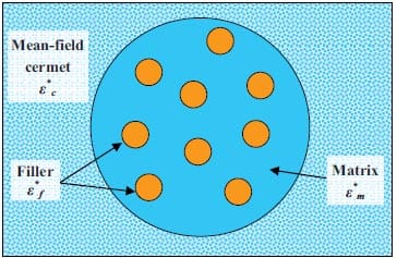
Figure 3.4: Scheme illustrating the Maxwell’s mean-field approach.
Based on the Maxwell-Wagner-Sillars theory, the complex dielectric constant of a mixture ε*c(w) can be calculated from the following equation:
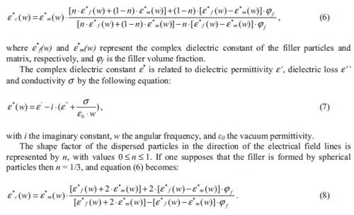
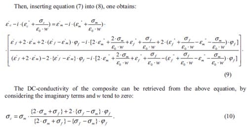
Equation (10) permits the calculation of the electrical conductivity for a mixture model. Unfortunately, this approach is applicable only to low filler volume fractions (i.e. below 20 %). The solution to this problem can be solved using another technique known as Bruggeman-Hanai model.
Bruggeman, using the results of Maxwell theory, introduced an asymmetrical integration technique to extend this theory to higher filler volume fractions (φf > 0.20). He assumed that the Maxwell equation can be used for calculating the infinitesimal increment of the mixture dielectric constant after adding an infinitesimal amount of filler particles to the material at any random position. These infinitesimal increments of the filler volume fraction are integrated to obtain a relation for the dielectric constant of heterogeneous material. Hanai [18] extended this approach to dynamic fields and conductive constituents starting from the Wagner equation. Again assuming spherical particles, i.e. n = 1/3, the following equation for the complex dielectric constant of a two components material ε*c(w) was obtained:
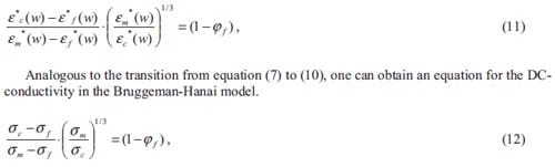
with the ceramic being the matrix and the metal the filler, the equation above will be used in predicting the electrical conductivity of highly filled cermet compositions.
Hence, using the Maxwell-Wagner-Sillars and Bruggeman-Hanai theories an electrical conductive model for composite materials based on the polarization phenomenon is available.
3.2. Selection of the electrical contact materials
Variations of the cermet electrical conductivity is determined numerically from equation (12) for composites with a ceramic matrix of TiB2, TiC or WC diluted with Ag, Cu or Al as an inert filler. The curves obtained are shown in figure 3.5 and provide an adequate description of the electrical conductivity of the materials prior to the development of any experiments.
As it can be observed in figure 3.5, the minimum and maximum values of electrical conductivity correspond to the pure ceramic and metallic compounds, respectively, also listed in table 3.2. The conductivity of these cermets is strongly affected by the amount of inert metal in mixture. For low concentrations of metal, the ceramic matrix is the main conductor phase and, the electrical conductivity tends to decrease when increases the ceramic content. One should notice that the estimated values of electrical conductivity obtained from the modelling are in the same order of magnitude compared to those obtained from literature for contact materials as silver metal oxides or silver refractory metals.
In general, the TiB2-based cermets present the highest values of electrical conductivity. Only when aluminium additions are larger than 50 vol.%, the electrical conductivity of TiB2-xAl cermets is lower than the one for WC or TiC-xAl cermets. The cermets with highest electrical conductivities are those with TiB2 and Ag or Cu as filler. Only for concentrations of metal higher than 40 vol.%, cermets with Ag present slightly higher values of electrical conductivity. The worst combination of compounds corresponds to the one of WC or TiC with Al as an inert metal phase or filler.
In general, the electrical conductivity for TiB2-based cermets with a metal volume fraction higher than 30 vol.% are characteristics of a good conductor material for high current applications.
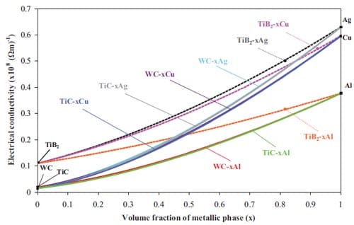
Figure 3.5: Calculated variation of the electrical conductivity of the final cermet as function of the volume fraction of metallic phase.
In this study, compounds with TiB2 and 40 wt.% of metallic filler, 52 vol.% of Al or 26 vol.% of Cu, are selected as the most promising to make a contact material with high resistance against electric wear, contact welding and at the same time electrically high conductive. In table 3.3 electrical conductivity values for cermets with 40 wt.% of filler are listed. The choice of a 40 wt.% metallic content is based on previous series of tests. For low metal contents, the SHS product resulted in a remarkably porous material because of the increase in exothermicity during the formation of the TiB2-based cermet. In addition, the 40 wt.% of metal phase is in accordance with the metallic content used for silver refractory metals fabricated by conventional routes [1].
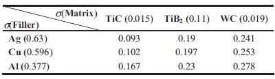
Table 3.3: – Electrical conductivity s (x 108 Ω-1·m-1) values for cermets with a 40 wt.% of inert metallic phase [14].
3.3. Sample preparation and experimental procedure
The steps followed in the combustion synthesis process to produce TiB2-based cermets are based on those described in chapter 2 for TiC-based functionally graded materials, see figure 2.11.
As starting reactant materials high-purity powders of amorphous boron (99.9 %, average particle size of 1 µm, H.C. Starck), and titanium (99.9 % pure, 45 µm, Gimex Technische Keramiek, The Netherlands) are used. As inert diluent materials copper (63 µm, Merck), and aluminium powder (45 µm, Mepura Metallpuver, Germany) are used in the experiments. High purity particles of alumina and carbon, with an average particle size of 45 µm, are used as constituents of the pressure transmitting media.
To obtain electrical contact materials stoichiometric mixtures of Ti and B are dry mixed with 30 or 40 wt.% of the inert metals copper or aluminium. The powders are uniaxially cold pressed in a steel die (figure 3.6, left) to 65-75 % of the theoretical maximum density (TMD) obtaining cylindrical pellets with a diameter of 21 mm and thickness of about 15 mm.
Green pellets are placed in the loosely packed pressure transmitting medium (PTM), see a detail of the die used for consolidation in figure 3.6 (right). The sample is ignited from below by a Kanthal coil through an ignitor pellet consisting of a titanium and boron stoichiometric mixture. A pressure between 250-400 MPa is then applied 5-8 seconds after ignition, for a total duration of 100 seconds. Due to loading and unloading the press, maximum pressure is maintained for 50 seconds. After consolidation, the sample remains inside the die for slow cooling, avoiding cracking due to thermal stresses. Figure 3.7 shows the green pellet and the reac
tion product once it is removed from the die.
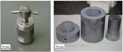
Figure 3.6: Photographs of the dies used during the different step of combustion synthesis followed by quasiisostatic pressing: compaction mould for green pellets (left); die used to perform the combustion synthesis and posterior consolidation (right).
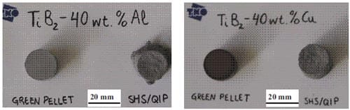
Figure 3.7: Cold pressed pellets of reactant materials, and the resulting material obtained by SHS and QIP. Photograph corresponds to a mixture of Ti, B and Al (left) and Ti, B and Cu (right).
3.3.1. Measurement of electrical resistivity
Once the cermet has been successfully synthesized, a mechanical and electrical characterization is performed in order to evaluate the final properties of the SHS product. A measure of its electrical conductivity as well as hardness is essential to verify whether TiB2-based cermets are good candidates to complement or substitute silver metal oxides and silver refractory metals, category I and II respectively. Density, formation of intermetallics and microstructure will be also studied as they do extensively influence the former properties.
To measure experimentally electrical conductivity values in the synthesized samples, the following equations have been considered:
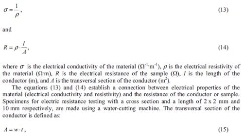
where s is the electrical conductivity of the material (Ω-1m-1), p is the electrical resistivity of the material (Ωx m), R is the electrical resistance of the sample (Ω), l is the length of the conductor (m), and A is the transversal section of the conductor (m2).
The equations (13) and (14) establish a connection between electrical properties of the material (electrical conductivity and resistivity) and the resistance of the conductor or sample. Specimens for electric resistance testing with a cross section and a length of 2 x 2 mm and 10 mm respectively, are made using a water-cutting machine. The transversal section of the conductor is defined as: A = w · t
where, t and w is thickness and depth (m) respectively, of the prismatic specimen. Four-point resistance measurements are performed, see figure 3.8. The four-point resistance circuit utilizes two wires to drive current through a resistance and two wires to measure the voltage drop across that resistance. Flat copper plates are placed on the ends of the sample to apply the current. Dielectric insulators are positioned between the copper plates and the claws to isolate the electronic circuit from its mechanical fixture. The function of the claws is to ensure the contact across the sample and the copper plates. The inter-electrode distance to determine the voltage in the sample is fixed to 10 mm.
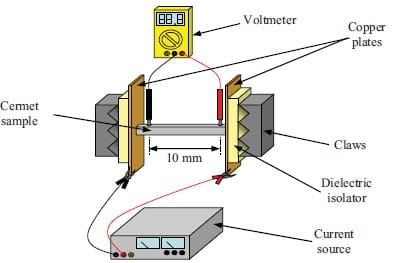
Figure 3.8: Schematic setup of the four-wire-bridge circuit used to measure resistance values: wires in black measure the voltage drop while wires in grey connect the current source with the sample.
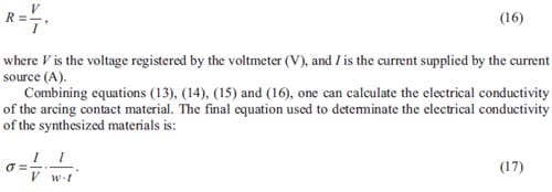
Samples are tested at current values of 5, 10, 15 and 20 A, with at least five values of voltage collected per current range. Experimentally due to the Ohmic heating, fluctuations of temperature during the performance of tests are observed, although not quantified. One may notice that the accuracy of the voltage registered by the voltmeter might be negatively affected by the thermal offsets.
3.4. Experimental results and discussion
Figure 3.9 shows the microstructure of a cross-section of a TiB2-40wt.%Cu cermet. The brightest regions represent the titanium diboride particles with a size below 10 µm. The darker fraction corresponds to the copper phase. The black spots represent remaining porosity. The microstructure appears refined and homogeneous.
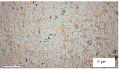
Figure 3.9: Optical micrograph of a TiB2-xCu cermet with a 40 wt.% Cu content.
X-ray diffraction analysis is performed on similar specimens, in this case figure 3.10 correspond to the X-ray diffraction results of a TiB2-40 wt.%Al. In this pattern the strongest peaks belong to the TiB2 and Al spectrum, here the inert metal content is high enough to be discerned. The absence of intermetallic peaks is an indication that neither the Al nor Cu phase has reacted with Ti, B and/or TiB2, which is an important notion regarding the desired final product. The presence of Al2O3 may be due to some rests of the PTM powder adhered to the sample. This phenomenon has already been observed for the synthesis of TiC-based cermets, in chapter 2.
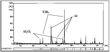
Figure 3.10: X-ray diffraction pattern of a TiB2-40wt.%Al cermet fabricated by combustion synthesis followed by quasi-isostatic pressing.
The final density of SHS products is determined by using the Archimedes method. Table 3.4 summarises the density results for TiB2-based cermets together with sample compositions and loads applied during the quasi-isostatic pressing stage after combustion synthesis for the various experiments. The relative density values of the TiB2-xAl cermets are always higher compared to TiB2-Cu cermets. The remaining porosity for the TiB2-based materials with Al as a binder is reduced to only 2 %. The large differences in final density for cermets with Cu or Al diluent can be explained by the fact the volume fraction of Al diluent is larger than the volume fraction of Cu, providing an enhanced ductile behaviour and hence facilitating the densification. Besides, Al has a lower melting point and is expected to remain longer in the liquid state.
The total energy release in the copper-diluted cermet is highest and it has been noticed that part of the copper is vaporized. A copper vapour has deposited a film on the inside of the combustion chamber. This fact explains the increase in porosity for cermets with Cu as an inert metal phase. Improvement of process parameters is needed to obtain high density TiB2-Cu cermets. A slight increase of the copper content should lower the combustion temperature of the system enough to prevent generation of copper vapour. As this inadvertent internal pressure build-up is avoided, one can expect the final porosity to decrease in the quasi-isotatic pressing. Further discussion of the thermodynamics of the SHS reactions is postponed to chapter 4.
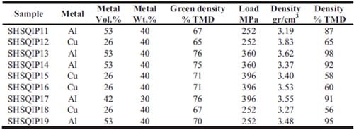
Table 3.4: Experimental values of density for TiB2-based cermets obtained via combustion synthesis and quasiisostatic pressing.
In order to evaluate the properties of TiB2-based cermets as materials for electrical contact applications, hardness and electrical conductivity are determined. Table 3.5 lists the measured final density, electrical conductivity and hardness of TiB2-xAl (x = 53 or 42 vol.%) and TiB2– xCu (x = 26 vol.%) cermets.
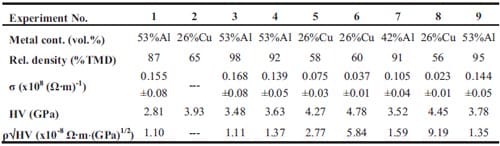
Table 3.5: Measured density relative to theoretical maximum density (TMD), electrical conductivity (δ), hardness values (HV), and p·HV values
of TiB2-based cermets obtained via SHS and QIP.
The TiB2-40wt.%Al samples show an electrical conductivity (s) ranging between 1.4 and 1.7 x10⁷ S·m-1, which is close to the calculated value for a fully dense sample of 2.3 x10⁷ S·m-1. This value is comparable to that of some WC-40wt.%Ag contact materials fabricated by sintering and metal infiltration. Values of electrical conductivity for copper-diluted cermets are still too low compared to the predicted values.
In figure 3.11, it can be observed the effect of porosity on electrical conductivity of the final cermet. Curves are plotted based on the electrical conductivity values shown in figure 3.5 for a fixed content of metallic phase in each curve. One can see that increasing the porosity leads to a decrease of conductivity; the electrical conductivity of a 50 % dense sample is lowered by 35 % of the value for a fully dense sample. Figure 3.11 shows that TiB2-based cermets containing 40 wt.% of Al (53 vol.%) present experimental conductivities between 30 and 18 % lower, in average, than the predicted values. In case of the sample with 30 wt.% of Al (42 vol.%) the conductivity is even 40 % lower than the predicted value for the same percentage of porosity. In samples containing 40 wt.% of Cu as a metallic phase, the measured values are lower by 52- 56 % of the predicted ones. It seems from comparison of the predicted and measured conductivity values that not all the metallic phase is participating in the conductive pathways from one electrode to the other electrode in the resistance measured. An impression of the conductivity pathways can be found in figure 3.9. The conductive pathways do increase with an increase in metallic volume.
In general, a low resistivity is desired in electrical contact applications. The hardness of the material is equally important because of the moving and sometimes even sliding contact. Vickers microhardness tests are performed in order to obtain an estimation of the hardness in dense areas of the sample. Table 3.5 lists hardness values (HV) of TiB2-xAl (x = 53 or 42 vol.%) cermets ranging between 2.8 and 3.8 GPa. This rather large range is caused by the porosity of samples, making good hardness measurements a difficult task.
The contact resistance, which is proportional to ρ·HV (with ρ=1/σ), is used as a design parameter for electrical contact materials. Values of ρ·HV have been determined and listed in table 3.5 as well. Comparing these values with those presented for silver metal oxides and silver refractory metals, one can observe that samples containing aluminium as inert metal do present values of ρ·HV close to those for silver metal oxides. Although the electrical conductivity values for the copper-diluted cermets appear rather low, the values of ρ·HV for these samples are still close to those listed for silver refractory metals due to the good values of hardness. However, it has to be remarked that those hardness values are obtained from microhardness tests i.e. in local areas, while the conductivity tests are performed over the bulk and here the effect of porosity cannot be avoided. Increasing slightly the Cu content may be a solution to avoid the copper vaporization and hence the extremely large formation of pores leading finally to an increase in electrical conductivity of the bulk material.
Figure 3.11: Predicted (curves) and experimental (dots) values of electrical conductivity including the effect of sample porosity for TiB2-based cermets.
3.5. Conclusions
- TiB2-based cermets for electrical contact applications have been fabricated by SHS with a subsequent densification step in a granulate medium.
- Selection is made based on electrical conductivity calculations of candidate materials.
- TiB2-based cermets with a 40 wt.% of Cu and 30-40 wt.% of Al are prepared. X-ray diffraction results indicate no formation of intermetallics, which could weaken the microstructure.
- The remaining porosity of cermets with Cu is about 40 %, while for cermets with Al it is only about 5 %. This large difference is caused by on the one hand the vaporization of Cu and on the other hand the larger volume fraction of Al and its lower melting point.
- The experimentally applied time-window is sufficient for densification of the TiB2- 40wt.%Al. Experimentally it is observed that the time-window for TiB2-based cermets with Cu binder, is not sufficient.
- Electrical and hardness measurements confirm that selection was successful and that SHS/QIP can lead to electrical contact application materials comparable to silver metal oxides and silver refractory metals.
- The measured electrical conductivity of the final cermets is lower than the predicted one due to the remaining porosity and the lack of conductive pathways connecting the two electrodes in the resistivity measurements.
3.6. References
- Slade P.G.: “Electrical Contacts: Principles and Applications”, Ed. Cutler-Hammer, Horseheads, NY, 1999, pp.681-748.
- Schrott O.: “Preparation of WC/Ag Contact Materials with Different Homogeneity”, Struers J. Materialography, Ed. Struers A/S, 40 (2003), pp.6-8.
- Bhaumik S.K., Divakar C., Singh A.K., and Upadhyaya G.S.: “Synthesis and Sintering of TiB2 and TiB2- TiC Composite under High Pressure”, Mater. Sci. Eng. A, 279(1-2) (2000), pp.275-281.
- Varma A., Rogachev A.S., Mukasyan A.S., and Hwang S.: “Combustion Synthesis of Advanced Materials: Principles and Applications”, Adv. Chem. Eng., 24 (1998), pp.79-226.
- Khina B.B., and Loban D.N.: “Modeling SHS in Porous Systems using Cellular Automata Approach”, Natl. Acad. Sci., 2000, pp.412-418.
- Moore J.J., and Feng H.J.: “Combustion Synthesis of Advanced Materials”, Prog. Mater. Sci., 39 (1995), pp.243-273.
- Holt J.B.: “Self-propagating High-temperature Synthesis”, Engineered Materials Handbook, Vol. 4: Ceramic and Glasses, Ed. ASM International, 1991, pp.227-231.
- Munir Z.A., and Anselmi-Tamburini U.: “Self-propagating High-temperature Synthesis of Hard Materials”, Hard Materials, Ed. Riedel R., Wiley VCH, Germany, 1999.
- Zuccaro G., Lapenta G., and Maizza G.: “Particle in Cell Simulation of Combustion Synthesis of TiC Nanoparticles”, Ed. Elsevier Science, Amsterdam, ISSN 0010-4655, 162(2) (2004), pp.89-101.
- LaSalvia J.C., Meyers M.A. and Kim D.K.: “Combustion Synthesis in the Ti-C-Ni-Mo System: Part I. Micromechanisms” J. Am. Ceram. Soc., 1995, pp.3001-3009.
- Zhang J., Lee J.H., Maeng D.Y., and Won C.W.: “Synthesis of Tungsten Monocarbide by Self-propagating High-temperature Synthesis in the Presence of an Additive”, J. Mater. Sci., 36(13) (2001), pp.3233-3238.
- Raman R.V., Rele S.V., Poland S., LaSalvia J.C., Meyers M.A., and Niiler A.R.: “The One-step Synthesis of Titanium Carbide Tiles”, J. Appl. Technol., 1995, pp.23-25.
- Olevsky E.A., Strutt E.R., and Meyers M.A.: “Combustion Synthesis and Quasi-isostatic Densification of Powder Cermets”, J. Mater. Process. Technol., 121 (2002), pp.157-166.
- Shackelford J.F., and Alexander W.: “CRC Materials Science and Engineering Handbook”, Ed. CRC Press, 2001.
- Vajeeston P., and Asokamani R.: “The Electronic Structure and Ground State Properties of Ti2B, TiB, and TiB2”, Anna University, Chennai, https://folk.uio.no/ravi/vaji/Ti2B.pdf.
- Munro R.G.: “Material Properties of Titanium Diboride”, J. Res. Natl. Inst. Stand. Technol., 105 (2000), pp.709-720.
- Steeman P.A.M.: “Interfacial Phenomena in Polymer Systems: A Dielectric Approach”, Doctor
al Thesis, Delft University of Technology, 1992. - Hanai T.: “Theory of Dielectric Dispersion due to Interfacial Polarization”, Kolloid-Zeitschrift, 171(1) (1960), pp.25-31.
Chapter Four
Kinetics of Self-sustained High-temperature Reactions1
In this chapter, a description of homogeneous combustion synthesis in condensed substances is presented. It is known that experimental investigation of the theoretical models is of great importance for developing the theory of combustion synthesis. A theoretical model is considered to estimate values of propagation wave velocity. In addition, the predicted values are compared with experimental measurements for the Ti + 2B and Ti + C based system. Al and Cu are used as diluents and their concentrations are varied systematically. Experiments are based on initiation and propagation of the combustion wave through a stack of cylinders with decreasing diameter. The effect of metal additions, diluent particle size, green density, and geometry is determined by measuring the combustion wave propagation velocity.
Results show that increasing the diluent content lowers the propagation velocity for both Cu and Al systems, being the propagation velocity in systems with Cu is higher than in systems with aluminium. The study of diluent particle size indicates that higher velocities are achieved with a larger aluminium particle size. Experimentally it has been shown that geometry does affect the propagation velocity. A decrease in diameter leads to a decay of velocity or even quenching of the reaction. For the Ti + 2B + 40 wt.% Al mixture a higher green density leads to higher values of propagation velocities in the studied density range. Finally, it has to be mentioned that the propagation velocity is very sensitive to temperature. One should carefully incorporate the effect of latent heat into the calculations of the combustion temperature and not simply approximate the combustion temperature solely based on specific heats of undiluted and diluted reactant mixtures. Activation energy Ea and pre-exponential factor term K0 describing first order kinetics have been experimentally determined. These values do compare to those in literature, but these relative small changes do explain the substantial differences in propagation velocity.
An introduction into theory of combustion wave in gives in paragraph 4.1. In paragraph 4.2 the fundamentals of homogeneous combustion of condensed substances are described. Various analytical models for the combustion wave propagation are presented in paragraph 4.3 and paragraph 4.4. In paragraph 4.5, combustion wave propagation velocities for the Ti + 2B and Ti + C metal diluted systems are predicted on basis of an adopted analytical expression for the propagation velocity of these systems. Experiments on combustion wave propagation velocities are as well described. Measured velocities are compared with predicted values and discussed in paragraph 4.6. In paragraph 4.7 conclusions are drawn.
4.1. Introduction
Combustion waves are an interesting phenomenon and they are considered in the theory of heat and mass transfer in chemically reacting systems. The occurrence of chemical conversion in wave regimes also finds broad application in energetics and technology. It is thus not surprising that there is an extensive literature on various aspects of combustion wave theory [1-20].
Propagation of a combustion wave is one of the possible modes for a combustion reaction [18]. The reactants have a relatively low initial temperature and are separated from the hightemperature reaction products by a narrow combustion zone (see figure 4.1). T0 is the initial reactant temperature while Tc is the combustion temperature. The combustion zone propagates into the reactant mixture with a fixed relative velocity un. This velocity is called laminar flame or laminar burning velocity.
Only deflagration waves, i.e. reaction waves travelling with appreciable though subsonic velocities, will be considered here. There are a few claims in literature that supersonic combustion waves can even exist in chemically reacting systems, which do not produce gases in the reaction [21, 22]. The detonation theory is a large special division in the theory of combustion and explosions, closely related to gas dynamics [4].
The initial reactant is stationary in figure 4.1 (left) and the combustion wave travels through it with the velocity un. However, a different scheme of the process is possible. The initial reactant in figure 4.1 (right) is fed to the reaction zone with the velocity un and the reaction products are withdrawn (with a velocity usually other than un). The combustion zone is then stationary. The first situation is typically encountered in combustion wave propagation through initially stationary media. The second occurs in various practical systems (e.g. furnaces, engines, etc.). In real systems, however, in contrast to figure 4.1 (right) the directions of the initial mixture flow and the normal to the combustion front do not coincide, as a rule, and the combustion front is not flat.
Figure 4.1: Ways of considering a wave regime of an exothermic reaction: combustion zone propagates over a fixed explosive (left); explosive is fed to a fixed combustion zone (right).
Systems with a reaction occurring in a combustion wave find broad application in current technologies e.g. gaseous mixtures of hydrocarbons with air are utilized in various spark-ignition engines, jet propulsion engines, etc.; explosives, gun powders and solid rocket propellants; fine sprays and dusts in engines and furnaces; pyrotechnic compounds used for various purposes; synthesizing refractory compounds in the combustion zone; synthesis of some metals or alloys and production of acetylene by incomplete oxidation of hydrocarbons [23-30].
It is obvious from the list that systems in which reactions can be run as a combustion wave are much diversified in their physico-chemical properties. The reactants and products can be gaseous, liquid, solid or particles and droplets suspended in gas. Many of the systems can be heterogeneous, with complex processes of mixing between the reactants occurring in the reaction wave. The combustion wave propagation in many technical systems is drastically affected by the gas flow turbulence.
As temperature in the combustion wave changes appreciably and a significant chemical conversion is attained, the physical material properties typically vary widely. This leads to additional difficulties in the development of a quantitative theory of combustion wave propagation and in the analysis of results for real systems.
Difficulties associated with consideration of a reaction with high conversions are specific to the study of the combustion wave propagation. They are not usually encountered in the study of such burning phenomena as thermal explosion or ignition where it is often sufficient to consider the phenomena before the temperature runaway, when conversion is still small, and e.g. zero order kinetics are applied.
The variety of phenomena and complicating factors in combustion wave propagation results in the existence of a number of branches in theoretical approaches and aims. It is difficult for this reason to make a satisfactory description of the main trends from a single point of view. However, the theory of deflagrations can be conditionally divided into two parts: physicochemical and fluid dynamics.
The combustion wave is characterized by chemical reactions leading to heat generation and temperature rise with accompanying heat and mass transfer. Specific features of heat and mass transfer allow division of com
bustion processes into two main classes, namely homogeneous and heterogeneous combustion [18]. The total effect of coupled heat and mass transfer, which determine the internal structure and velocity of the combustion wave, is studied in the physicochemical theory for both homogeneous and heterogeneous burning. The effect of the flow field on the combustion wave or vice versa, the effect of the combustion wave on characteristics of the flow (laminar or turbulent), is treated in the fluid-dynamic theory.
Systems with homogeneous combustion remain uniform throughout the process, so transport and mixing of components are not necessary for reaction and heat generation. However, this does not mean that diffusion is not important. The best-known example of homogeneous combustion is the burning of premixed gases consisting of fuel and oxidizer. Homogeneous combustion also comprises burning of a number of condensed and gasified species in which exothermic reactions of molecular decomposition or coupling can occur.
In the case of heterogeneous combustion, the system is most often macroscopically nonuniform when combustion is initiated, or it becomes non-uniform during combustion. Chemical reactions and heat generation in heterogeneous combustion often occur at the phase boundary or in several phases and may be accompanied by phase transitions. The rate of heterogeneous combustion is usually limited by transport phenomena. Systems with heterogeneous burning include various condensed and dispersed systems with different properties and modes of burning (various fuel droplets in a gaseous oxidizer, porous fuels into which the oxidizer is fed by infiltration, etc.) [20, 31].
This chapter is restricted to the theory of combustion in homogeneous media, even though the reactant mixture is a dispersion and therefore heterogeneous. The theory of combustion wave propagation in heterogeneous media involves various complications and has to be developed separately for different types of heterogeneous combustion. For homogeneous combustion, there are fewer complications. Attention will be focused on problems that have a general significance for combustion wave theory.
4.2. Fundamentals of homogeneous combustion of condensed substances
Fundamentals of the current physico-chemical theory of the combustion wave propagation are based on simultaneous consideration of chemical kinetics and heat and mass transfer. These models were formulated in the 1930’s and 1940’s for gas mixtures by Lewis and von Elbe, Zel’dovich and Frank-Kamenetsky, Belyaev and others. Lewis and von Elbe [32] determined an empirical relationship between flame velocity and the kinetics of a chemical reaction. Zel’dovich and Frank-Kamenetsky [4] derived first a formula for flame velocity. These studies were further developed both to specify mechanisms of chemical reactions and hydrodynamics of gas flow. The experimental work of Belyaev [19] was essential in developing the theory of homogeneous combustion of condensed substances. Analysis of his work helped to propose a combustion mechanism for explosives. Later on, Zel’dovich described mathematically the combustion mechanism in solid-state reactions based on flame propagation in gas mixtures.
Many exothermic solid-solid or solid-liquid reactions, after being ignited locally, can release enough heat to achieve the self-propagating mode throughout the sample without the need of additional energy [1-3]. The liberated heat creates a combustion front with a propagating reaction zone of finite thickness, thereby synthesizing the final product. Modelling the Selfsustained High-temperature Synthesis (SHS) reaction involves not only the thermodynamics and kinetics of the reaction, but also physical phenomena associated with ignition (i.e. melting of reactants and/or diluents), combustion wave propagation mechanisms, heat losses (related with the sample size and shape), porosity and thermal conductivity of both reactants/diluents and products. Experimental investigations on SHS reactions can provide data on wave characteristics and propagation rates, which may be used to validate a proposed model.
SHS reactions have two basic stages: ignition and propagation of the reaction. The thermal theory has been used most widely in dealing with the ignition processes. However, thermal theory describes only the heat generation and conduction without taking into account the diffusion processes that proceed during the reaction.
A schematic picture of the combustion wave as a plane of reaction propagating through the reactant mixture is given in figure 4.2. Since the SHS reaction is usually fast, the first assumption made for the modelling is that the process occurs under adiabatic conditions. The unreacted starting mixture, with an initial temperature T0, is heated to the ignition temperature due to energy released from the chemical reaction. The region ahead of the wave is the heat-affected zone in which the temperature increases from T0 to the ignition temperature. Once the reaction begins, and the wave is propagating at a constant rate, a steady temperature distribution is established. The reaction or combustion zone dw is the region in which the SHS reaction is initiated and completed and hence where most of the chemical and physical conversions take place. The thickness of the zone is defined by the degree of completion of the reaction η from 0 to 1. The rate of the reaction Φ becomes greater than zero when the ignition temperature is achieved and will be a maximum at some position within the combustion zone, as shown in figure 4.2. This represents an ideal situation where dw is relatively thin. Such reactions are associated with low activation energy barriers.
The thickness of the reaction zone is therefore dependent on the kinetics of the reaction. Reactions that have strong kinetic control will have wider reaction zones and different spatial distributions of T, η and Φ, see figure 4.3. The combustion front can be then defined by the temperature rather than the degree of completion of the reaction. If this is so, the extent of the effective combustion front is much smaller than the distance between η = 0 and η = 1. Under these conditions, the section from the end of the effective combustion zone and total completion of the reaction is known as the after burn region.
Figure 4.2: Spatial distribution of the temperature T, degree of conversion ?, and heat generation rate f for a propagating combustion wave with a narrow reaction zone.
Figure 4.3: Spatial distribution of the temperature T, degree of conversion ?, and heat generation rate f for a propagating combustion wave with after-burn region or heat generation delay, where Tj is temperature, Φf is conversion, ηf is reaction rate at the end of the combustion front. The thickness δw cannot be compared directly to figure 4.2.
Models for homogeneous combustion can then be divided in two groups:
- Combustion models where the combustion rate or combustion wave propagation velocity, depends on total conversion of initial substances into final or intermediate products.
- Combustion models where the combustion rate depends on incomplete conversion of the initial substances in the reaction zone.
The heat generation rate in classical theory of combustion is mainly controlled by temperature, while in SHS processes it can be also strongly dependent on conversion. Models of the second group are characterised by a delay in heat generation due to the incompleteness of reaction. This phenomenon is due to certain physico-ch
emical processes such as evaporation, sublimation or dispersion. Owing to these processes, some of the reactants are carried away from the reaction zone in a dispersed state. It is assumed that further conversion does not affect the combustion rate. Formation of a combustion surface is characteristic of the processes with incomplete conversion of the substance. Models of the second group present a major complexity than models of the first group [5-7]. In this chapter, only models from the first group will be considered.
4.2. Fundamentals of homogeneous combustion of condensed substances
The governing equation for combustion synthesis of a material system is given by Fourier’s heat conduction equation including a term for the heat generation:
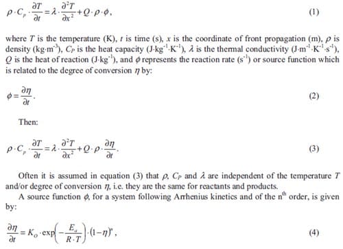
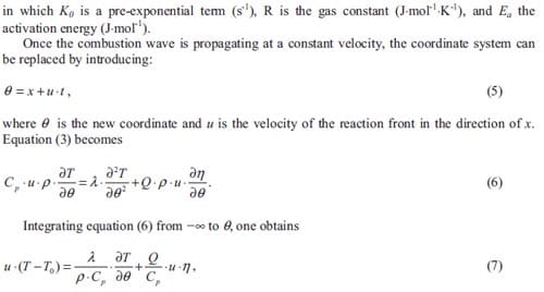
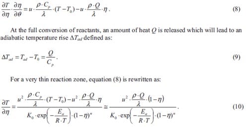
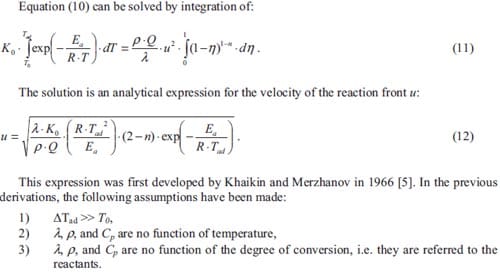
4.4. Modified models for homogeneous combustion
In Self-sustained High-temperature Reactions, the heat or enthalpy of reaction is needed in order to heat up the unreacted material sufficiently and increase the reaction rate. It is well known that the properties of the reactants ahead of the combustion front may be considerably different from those of the products behind the combustion front. Hence, the expression given in equation (12), derived by Merzhanov, cannot be used in most of the systems. Therefore, new models have been developed by various researchers [8-17, 20, 31] in order to include the effect of not only thermophysical properties of reactants and products but also porosity, diluent additions, phase changes, heat losses and particle size on the combustion front velocity.
Lakshmikantha et al. [8, 9] derived analytical equations for the combustion wave propagation velocity incorporating the effect of the different properties of reactants and products such as thermal conductivity and density. It is shown that porosity also influences the nature of combustion and hence the same values of velocity may be obtained at different porosities. The effect of green density on the reaction front velocity has been thoroughly studied [2, 14-16]. Special mention must be given to the study by Rice [16] where it is observed that the propagation rate as a function of the green density presents a maximum, which depends on particle size of the reactants. It is known that the presence of a liquid phase enhances the kinetics of the system. Smolyakov et al. [10] studied the effect of an inert low melting additive in combustion synthesis, and formulated analytical solutions for the front velocity including thermal properties of the low-melting inert diluent. Smolyakov showed that the combustion pattern must be studied considering the different regimes provoked by the diluent phase transformations. In regimes controlled by the phase transformation, the combustion velocity is independent of the amount of inert diluent. All these formulated expressions are in essence based on the model developed by Merzhanov in 1966.
The reactant particle size is also supposed to influence the combustion wave propagation velocity. So far, researchers have studied the effect of the particle size of the melting reactant [2, 3, 8, 11-13]. Analytical solutions for the combustion front velocity have been derived only by adopting diffusion kinetics [20, 31], i.e. heterogeneous combustion, which requires an assumption of the geometry of the reactants, and hence includes the reactant particle size as a parameter. Merzhanov’s approach does not include explicitly the effect of the particle size; presumably, any such effect is contained in the empirically determined constant K0.
It is known that the heat losses depend on the shape of the samples and quenching of the reaction can be achieved when heat losses are larger than the heat production. Lau et al. did perform experiments in which the goal was to quench the reaction due to the adopted geometry [17]. In our study, heat losses will be considered by varying the diameter of the samples. An influence on the kinetics of the process is expected to be found.
4.4.1. Analytical model considering physical and chemical properties of reactants and products
In this section, the formulations obtained by Lakshmikantha et al. [8] are presented. In this case, λ in equation (1) is considered to be a function of reactants and products by applying the rule of mixtures. Still they are supposed to be independent of temperature. Under this consideration, equation (6) becomes:
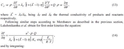
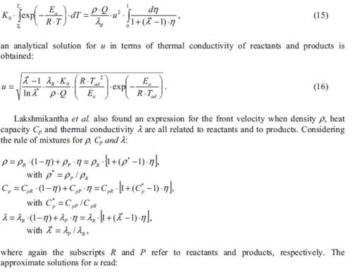
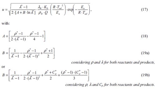
One has to realize that the application of the rule of mixtures is analytically correct for the density and heat capacity. For the thermal conductivity, the rule of mixtures is only an approximation. Better models, even analytical, do exist [33]. However, integration of equation (14) will become complex if not impossible.
4.4.2. Analytical model considering nonreacting diluents
Lakshmikantha et al. in their study took also into account the influence of an inert additive on the system kinetics. The general expression for the heat equation (6) becomes:
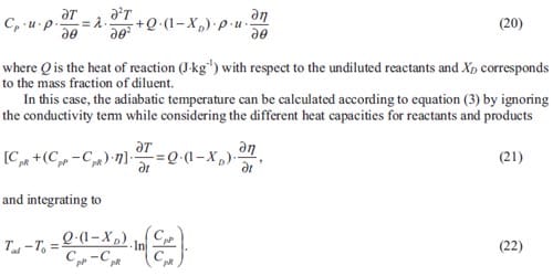
Usually the combustion temperature is close to the adiabatic temperature of a given reaction system. The propagation or front velocity can be obtained by substituting the combustion temperature obtained from equation (22) into the following expression:
4.5. Experimental procedure
This paragraph will be divided in two parts. Initially, predicted values for the combustion wave propagation velocity are calculated based on an expression described in paragraph 4.4.2. Next, the experimental procedure followed in order to perform the combustion wave propagation velocity tests for the Ti + 2B and Ti + C metal diluted system is described.
4.5.1. Estimation of combustion wave velocity
To study the kinetics of SHS processes, it has been proposed considering the systems Ti + 2B and Ti + C, at stoichiometric ratio, diluted with a low melting inert metal. Aluminium and copper are considered as inert diluents based on the X-ray diffraction analysis presented in chapter 3. It is shown that Al and Cu, apparently, do not react with titanium and/or boron. Although no X-ray diffraction analysis has been done for the Ti +C + Al system, based on former experiences Al is chosen as an inert diluent for the Ti + C system.
Here the effects of reactants and products properties are taken into account. Because a diluent is added to the pure stoichiometric reactant mixture, equation (23), derived by Lakshmikantha et al. [8], will be used to calculate predicted values of combustion front velocity for our SHS systems.
Combustion temperatures will be calculated and two different me
thods to obtain values of combustion temperature are considered. Equation (22) is chosen as a first approximation for the combustion temperature. However, in this expression the possible diluent phase changes are not taken into account. Furthermore, the heat capacity for both reactants and products are supposed to be independent of temperature.
In order to obtain more accurate values of the combustion front velocity, a second method to calculate the combustion temperature considering the heat capacity as a function of the temperature, as well as the latent heat L (J·Kg-1) at the melting and/or boiling point of the inert diluent, is proposed. The following heat balance equation is considered:

where v1D and v2D represent the fraction of diluent that melts or evaporates respectively. In order to calculate the thermal and physico-chemical properties of the reactant mixture as well as the product, the rule of mixtures has been applied. Porosity has been considered in the theoretical calculations: an initial porosity of 30 % is considered, a typical value for a reactant composition in SHS. The final porosity is fixed to 50 %, which is then a typical value of porosity in SHS reactions without further consolidation [1-3]. The effect of porosity has been taken into account to calculate p, Cp, and λ of reactant mixture and product.
4.5.2. Sample preparation
High-purity (99.9 %) titanium powder (Gimex, The Netherlands) with an average particle size < 45 µm (-325 mesh), boron amorphous powder (H.C. Starck, Germany) with an average particle size of 1 µm and a purity of 99.9 %, and high-purity (99.5 %) carbon powder (Sigma Aldrich Chemie, The Netherlands) with an average particle size of 10 µm are chosen as reactant powders. Copper powder (Merk, Germany) 99.7 % pure and with an average particle size < 63 µm (-230 mesh), and aluminium powder (Mepura Metallpulver, Austria) with a purity of 99.5 % and three different particle sizes 1.2, 45 and 125 µm, are used in the experiments as inert metal diluents.
Powders are dry mixed in order to obtain stoichiometric mixtures of Ti + 2B + x·Diluent and Ti + C + x·Diluent, with x = 20, 30, 40 and 50 wt.% of Al and/or Cu. Cylindrical green pellets with diameters varying from 27 to 6.5 mm and constant height of 30 mm are obtained by stacking layers of the powder mixtures, followed by cold uniaxially pressing in steel tubes. The various applied pressures result in green densities of 65 and 70 % of the Theoretical Maximum Density (TMD) for all compositions.
Two different configurations are considered to measure the combustion front velocities: 1) a stack of cylinders with decreasing diameter where the reaction is initiated at the side with the largest diameter; 2) cylinders are ignited independently. A schematic representation of the set up for configuration 1 is shown in figure 4.4.
The dimensions of steel tubes have been calculated in order to minimize the heat losses to the surroundings while the combustion wave is propagating along the cylinders with decreasing diameter. The ratio diameter/wall thickness was kept constant for the seven cylinders.
Figure 4.4: Detail of a seven tubes configuration for combustion front tests: cold uniaxial pressing of initial powder mixtures is achieved (left), tubes are coupled in order to form the stack of cylinders considered in configuration 1 (right).
Figure 4.5 represents a scheme of the experimental set-up. The SHS reaction always starts from the largest cylinder. Here the ignitor, a steel plunger with a 0.3 mm diameter Kanthal wire, is connected to a current source. A cavity between the plunger and the pressed reactant powder is filled with loose powder of pure Ti + 2B. A current of 4.5 A ignites the loose powder after 2 seconds which then ignites the pressed reactant powder. In order to measure values of combustion wave propagation velocity, holes have been drilled in each cylinder at a constant distance of 30 mm. A set of glass fibres is aligned to the holes capturing the moment the reaction front passes. The alignment is accurately achieved by the use of small tubes welded to the cylinders acting as a coupling element. In order to avoid movement of the cylinders while SHS occurs, the stack of tubes is mounted in a bank with a spring-back system, which keeps the cylinders in a correct position and, at the same time, allows longitudinal expansion of the SHS product. The glass fibres are connected to a digital camera (Canon Photoshot) and/or coupled to photodiodes, which are connected to oscilloscopes (LeCroy). Furthermore, a high definition video camera (Sony Handycam® HDR-FX1) is capturing the experiment inside the combustion chamber. Signals are processed by means of the program Origin 7.0 and special computer software for video editing (HT Video Editor 6.0).
Figure 4.5: Schematic set-up of experiments, with constant spacing between glass fibres (left); view of the stack of cylinders in configuration 1, aligned with the glass fibres (right).
4.6. Results and discussion
This paragraph is divided in two parts. Firstly, predicted combustion wave propagation velocity values are presented. The second part is dedicated to the experimental results and comparison between predicted and experimentally measured combustion front velocities.
4.6.1. Estimated combustion wave velocity
Values of propagation velocity according to equation (23) are calculated considering a green density of reactants mixture close to 70 % TMD while the final density of the product is 50 % TMD. The latter value is typical in SHS processes without assisted densification. Hence the effect of air on the thermo physical properties of reactants and products (Cp, λ and ρ) is included as well by applying the rule of mixtures.
Values of combustion temperature Tad, according to equation (22), and Tc according to the heat balance considered in equation (27) are calculated in order to estimate predicted values of propagation velocity. Thermodynamic data concerning reactants and products are obtained from various Handbooks of Chemistry. Table 4.1 lists values of Tad and Tc for the Ti + 2B and Ti + C based system. The effect of diluent phase transitions on the combustion temperature can be observed from the large differences between Tad and Tc. Values of Tc listed in italic are obtained assuming that only a certain amount of diluent evaporates. The values of Tad obtained with equation (22) are unrealistically high; these temperatures are sometimes exceeding the experimentally determined combustion temperature of the undiluted reaction. Therefore, this approximation cannot be used in the calculation of propagation velocity, as one may not ignore the latent heat of melting and/or evaporation.
The calculated propagation velocity as a function of the diluent content is given in figure 4.6, with K0 = 1·1010 s-1 and Ea = 3.18·105 J·mol-1 for the Ti + 2B system and K0 = 5·104 s-1 and Ea = 1.24·105 J·mol-1 for the Ti + C system [9]. The propagation velocity decreases when the amount of diluent increases as the heat generation Q·(1-XD) per unit of mass becomes smaller and the combustion temperature decreases.
Propagation velocities for the Ti + C based system are always lower
than for the Ti + 2B based system. This is due to not only the lower Tc but also the lower value of K0.
Within the Ti + 2B based system the mixtures with copper as diluent, show always higher propagation velocities compared to mixtures with aluminium. This can be explained from the larger combustion temperatures for mixtures with copper and from the fact that copper does posses a larger thermal conductivity, which for the same green density, leads to a faster preheating of the reactants ahead the reaction front.
Table 4.1: Theoretical values of combustion temperature for the Ti + 2B and Ti + C based systems. Tc is based on equation (27) and Tad is based on equation (22).
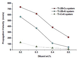
Figure 4.6: Calculated propagation velocity values as a function of the content of Al or Cu for the Ti + 2B and Ti + C systems
4.6.2 Experimental results
A sequence of frames, showing the evolution of the combustion wave along the stack of cylinders, is given in figure 4.7. Here one can observe how relatively fast the reaction initiates and propagates along the seven tubes. The SHS reaction does initiate and propagate until the end of the first tube in less than 2 seconds. The violence of the reaction for a Ti + 2B + 50 wt.%Cu system is clearly observed from the sequence of images in figure 4.7.
Experimental results indicate that for a given green density, the reaction does propagate faster in mixtures with a smaller content of diluent. The front velocity slows down with decreasing diameter as the effect of heat losses becomes more important. In some cases, the reaction is quenched when propagating along the smallest diameters. This phenomenon can be observed in figure 4.8. Mixtures containing copper do show a larger propagation velocity than mixtures with aluminium. This was already demonstrated theoretically in figure 4.6. The remarkably high values of velocity for the smallest diameter in systems containing Cu can be explained by the fact that for these systems a jet of molten material is pushed ahead of the combustion front, seemingly fastening the propagation of the front. Actually the internal pressure is not only due to heating of the entrapped air, but also due to the boiling of the copper.
A representation of the propagation velocity versus the aluminium content is given in figure 4.9. One can observe the decay in propagation velocity with increasing aluminium content. This effect was already postulated above when presenting the theoretical calculations for the front velocities. The obtained results present a similar tendency of that reported by Fu et al. [11]. However, figure 4.8 and figure 4.9 shows much lower values of propagation velocity than those theoretically calculated.
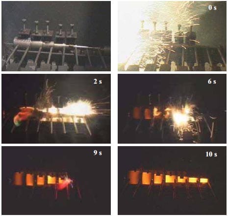
Figure 4.7: Sequences of the evolution of the combustion wave for a Ti + 2B + 50 wt.%Cu system. Ignition is achieved at the beginning of the largest tube; combustion wave propagates in a self-sustained way until the end of the stack of cylinders decreasing in diameter.
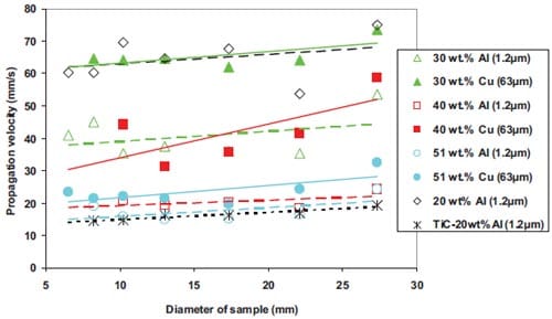
Figure 4.8: Experimental propagation velocity as a function of the sample diameter for the Ti + 2B system with indicated amount of Al and Cu, and a green density close to 65 %TMD.
Figure 4.10 indicates the effect of green density on the propagation velocity. Apparently, a higher propagation velocity is observed for a higher green density. One may expect that a higher green density promotes the quenching of the reaction as the thermal conductivity of unreacted layers becomes larger and broadens the reaction zone. However, no evidence is seen of this effect with the Ti + 2B + 40 wt.%Al system in figure 4.10. It may be that for this system, the two considered densities are still below the maximum reported by Rice et al. [16] and a higher green density is needed to undergo a decrease in propagation velocity and an eventual quenching of the reaction.
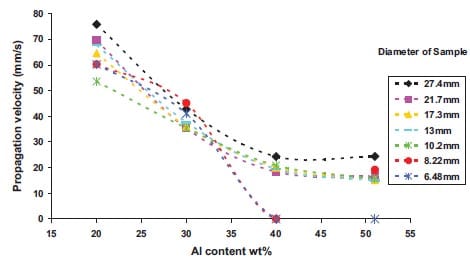
Figure 4.9: Propagation front velocity as a function of the aluminium content for the Ti + 2B + xAl (1.2 µm) system with a green density close to 65 %TMD for several sample diameters.
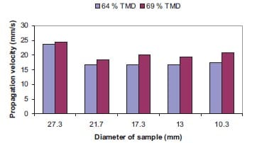
Figure 4.10: Propagation velocity values for the Ti + 2B + 40 wt.%Al (1.2 µm) system with green densities close to 65 and 70 %TMD.
Results given in figure 4.11 show the effect of diluent particle size on propagation velocity. Excluding two atypical values measured for 20 wt.% Al, the tendency is that a higher propagation velocity is achieved when the particle size of Al diluent is increased. This phenomenon also occurs for the Ti + C based system. Only in a Ti + 2B based system with 40 wt.% Al, this tendency is not observed. These results may contradict those obtained by Moore et al. [2] and Munir et al. [3]. However, they considered the effect of reactant and not diluent particle size. The hypothesis is that the melting diluent facilitates the diffusion of the reactants and thus increases the reaction rate. This does not necessarily mean that small diluent particles also increase the propagation rate. For large diluent particles, there exits a closer contact between the reactants; with coarse aluminium particles and for same aluminium content in mixture, particles of titanium and boron do interact easily as those are occupying the voids left by the aluminium particles. Fine aluminium particles act as an interaction barrier and particles of titanium and boron do need more time to migrate and consequently interact yielding a slower reaction.

Figure 4.11: Representation of the propagation velocity as a function of the sample diameter for the Ti + 2B + xAl and Ti + C + xAl system for different aluminium particle sizes.
The values of propagation velocity are comparable to those for configuration 1 both comparing diluent content and sample diameter. As the experimental propagation velocities are different from the calculated ones, the experimental data of figure 4.11 has been plotted to the equations given before. In order to obtain a value of the activation energy, according to equation (23) one can plot ln(u/Tc) as a function of 1/Tc, yielding a straight line with a slope related to Ea. This general principle still applies even for systems with phase transitions under the assumption of Arrhenius-type kinetics [15]. For the data corresponding to the Ti + 2B + xAl system at 65 %TMD with 45 µm Al particles and a sample diameter of 21.7 mm, one obtains the following values for the kinetic parameters: Ea = 4.5·105 J·mol-1 and K0 = 2.6·1011 s-1. These values are larger than those adopted from literature for the theoretical calculations in figure 4.6, i.e. Ea = 3.18·105 J·mol-1 and K0 = 1·1010 s-1. Even though K0 may vary, the activation energy Ea is expected to be the same for the undiluted and diluted Ti + 2B system [34].
In figure 4.12, the fitted and experimental propagation front velocity values are plotted. These results may indicate that despite the X-ray diffractio
n analysis for the Ti + 2B + xAl systems, the aluminium does take part in the SHS reaction at least at very early stages. This can be the reason why no peaks belonging of intermetallics phases are detected in the X-ray diffraction pattern. To this respect, Rogachev et al. developed a study of the phase evolution in the Ti + C + xAl and Ti + 2B + xAl systems [35]. Here, it is reported that disappearance of initial phases and formation of the first products (TiC or TiB2) happen during a short time interval, at the most 40 ms (time resolution of the method). Therefore, the first products of combustion reactions are refractory titanium carbide or diboride and melt. Then temperature decreases and other phases precipitate from the melt according to phase diagram. However, the systems studied by Rogachev et al. do not correspond to the stoichiometric composition but with titanium in excess. Therefore, a further analysis using time-resolved synchrotron X-ray diffraction is needed to confirm this fact.
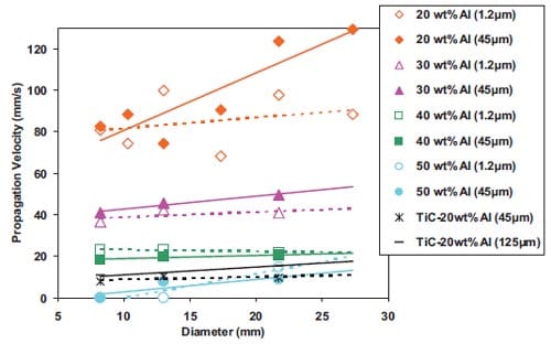
Figure 4.12: Propagation velocity versus diluent content for the Ti + 2B + xAl system (experimental in black, fitted in grey).
4.6.2 Experimental results
- The main approaches regarding the description of homogeneous combustion synthesis in condensed substances have been presented.
- A theoretical model to estimate values of propagation wave velocity has been applied and compared with experimental measurements for the Ti + 2B and Ti + C based system.
- Both theoretical and experimental results show that the propagation velocity in systems with copper as a diluent is higher than in systems with aluminium. Increasing the diluent content lowers the propagation velocity for both Cu and Al systems.
- The study of diluent particle size indicates that higher velocities are achieved with a larger aluminium particle size.
- Experimentally it has been shown that geometry does affect the propagation velocity. A decrease in diameter leads to a decay of velocity or even quenching of the reaction.
- For the Ti + 2B + 40 wt.%Al mixture a higher green density leads to higher values of propagation velocities in the studied density range.
- The propagation velocity is very sensitive to temperature. The effect of latent heat needs to be incorporated into the calculations of the combustion temperature. Approximating the combustion temperature based on specific heats of undiluted and diluted SHS reactant mixtures brings to unrealistic values of combustion temperature.
- Activation energy Ea and pre-exponential factor term K0 are system specific and have been experimentally determined for the Ti + 2B + Al system.
- The prediction of front velocities cannot be made just based on reactants and products when an inert metallic diluent is considered. At very early stages, the metallic diluent may take part in the reaction affecting thus the kinetics of the system.
4.8. References
- Merzhanov A.G.: “Theory and Practice of SHS: Worldwide State of the Art and the Newest Results”, Int. J. SHS, 2 (1993), pp.113-157.
- Moore J.J., and Feng H.J.: “Combustion Synthesis of Advanced Materials: Reaction Parameters”, Progr. Mater. Sci., 39 (1995), pp.275-316.
- Munir Z.A., and Anselmi-Tamburini U.: “Self-propagating Exothermic Reactions: The Synthesis of High- Temperature Materials by Combustion”, Mater. Sci. Rep., 3 (1989), pp.277-365.
- Zel’dovich Ya.B., and Frank-Kamenetskii D.A., Zh. Fiz. Khim., 12 (1938), p.100.
- Khaikin B.I., and Merzhanov A.G.: “Theory of Thermal Propagation of a Chemical Reaction Front”, Combust. Explosives and Shock Waves, 2 (1966), pp.22-27.
- Merzhanov A.G.: Arch. Procesow Spalania, 5(1) (1974), p.17.
- Merzhanov A.G.: “SHS-process: Combustion Theory and Practice”, Arch. Comb., 1 (1981), pp.23-48.
- Lakshmikantha M.G., and Sekhar J.A.: “Analytical Modeling of the Propagation of a Thermal Reaction Front in Condensed Systems”, J. Am. Ceram. Soc., 77(1) (1994), pp.202-210.
- Lakshmikantha M.G., and Sekhar J.A.: “An Investigation on the Effect on Porosity and Diluents on Micropyretic Synthesis”, Metall. Trans. A, 24A (1993), pp.617-628.
- Smolyakov V.K.: “Inert Additive Melting in a Gasless Combustion Wave”, Combust., Explosives and Shock Waves, 38(5) (2002), pp.559-565.
- Fu Z.Y., Yuan R.Z., Munir Z.A., and Yang Z.L.: “Fundamental Study on SHS Preparation of TiB2-Al Composites”, Int. J. SHS, 1(1) (1992), pp. 19-124.
- Li H.P., and Sekhar J.A.: “The Influence of the Reactant Size on the Micropyretic Synthesis of NiAl Intermetallic Compounds”, J. Mater. Res., 10(10) (1995), pp.2471-2480.
- Li H.P.: “Investigation of Propagation Modes and Temperature/Velocity Variation on Unstable Combustion Synthesis”, J. Mater. Res., 17(12) (2002), pp.3213-3221.
- Bhattacharya A.K.: “Green Density of a Powder Compact and Its Influence on the Steady-State Wave Velocity in Combustion Synthesis of Condensed Phase”, J. Am. Ceram. Soc., 74(9) (1991), pp.2113-2116.
- Kachelmyer C.R., Varma A., Rogachev A.S., and Sytschev A.E.: “Influence of Reaction Mixture Porosity on the Effective Kinetics Gasless Combustion Synthesis”, Ind. Eng. Chem. Res., 37 (1998), pp.2246-2249.
- Rice R.W.: “Review Microstructural Aspects of Fabricating Bodies by Self-propagating Synthesis”, J. Mater. Sci., 26 (1991), pp.6533-6541.
- Lau C., Mukasyan A.S., and Varma A.: “Reaction and Phase Separation Mechanisms during Synthesis of Alloys by Thermite Type Combustion Reactions”, J. Mater. Res., 18(1) (2003), pp.121-128.
- Merzhanov A.G., and Khaikin B.I.: “Theory of Combustion Waves in Homogeneous Media”, Progr. Energy Combust. Sci., 14 (1988), pp.1-98.
- Belyaev A.F., Zh. Fiz. Khim., 12 (1938), p.94.
- Hardt A.P., and Phung P.V.: “Propagation of Gasless Reactions in Solids I. Analytical Study of Exothermic Intermetallic Reaction Rates”, Combust. Flame, 21 (1973), pp.77-89.
- Merzhanov A.G., Gordopolov Y.A, and Trofimov V.S.: “On the Possibility of Gasless Detonation in Condensed Systems”, Shock Waves, 8 (1998), pp.157-159.
- Gur’ev D.L., Gordopolov Y.A., Batsanov S.S., Merzhanov A.G., and Fortov V.E.: “Solid-state Detonation in the Zinc-sulfur System”, Appl. Phys. Lett., 88 (2006), pp.024102-1:3.
- Cooper F.M.: “Solid Propellant Controlled Rocket Motors”, US Patent 3.712.058, January 1973.
- Heier W.C.: “Molded Composite Pyrogen Igniter for Rocket Motors”, US Patent 4.080.901, March 1978.
- Furbringer C., and Pauling H.: “Explosive and Propellant Composition and Method of Preparation”, US Patent 4.881.993, 21 November 1989.
- Wong J.: “Propellant Formulation and Process”, US Patent 5.404.813, 11 April 1995.
- Laucht H., Mueller G., and Welser W.: “Igniting Element”, US Patent 6.332.399, 25 December 2001.
- Rothman B.: “Pyrotechnic Noisemaker”, US Patent 4.005.657, 1 February 1977.
- Wells J.E.: “Apparatus and Process for Producing Predominately Iron Alloy Containing Magnesium”, US Patent 4.519.838, 28 May 1985.
- Baldi A.L.: “Metal Treatment”, US Patent 5.182.078, 26 January 1993.
- Amstrong R.: “Models for Gasless Combustion in Layered Materials and Random Media”, Combust. Sci. Technol., 71 (1990), pp.155-174.
- Lewis B., and von Elbe G.J., J. Chem. Phys., 2 (1934), p.537.
- Russell H.W.: “Principles of Heat Flow in Porous Insulators”, J. Am. Ceram. Soc., 18 (1935), pp.1-4.
- Oral communication at the 11th International Ceramics Congress, CIMTEC 2006.
- Rogachev A.S., Gachon J.C., Grigoryan H.E., Vrel D., Schuster J.C.
and Sachkova N.V.: “Phase Evolution in the Ti-Al-B and Ti-Al-C Systems during Combustion Synthesis: Time resolved Study by Synchrotron Radiation Diffraction Analysis”, J. Mater. Sci., 40 (2005), pp.2689-2691.
Chapter Five
Energetic solids such as thermites, intermetallic mixtures or Metastable Intermolecular Compounds may react to release chemical energy. This energy can be tailored for different purposes. Energetic fragments initially deliver its kinetic energy to a very small area of the target, perforating or penetrating it. At the later stage, chemical energy is released and damage is greatly increased. The chemical reaction is initiated due to mechanical deformation at impact.
In this chapter, the ignition of energetic materials due to mechanical deformation and in particular shear deformation is studied. Studying the deformation mechanism by means of computer simulations involves a great complexity. However a study of deformation and sensitivity to impact in the Ballistic Impact Chamber Test, supposes a close resemblance, assuming shear rate is the parameter that controls initiation
Experiments on shear initiation of Al / MoO3 mixtures are performed with the Ballistic Impact Chamber and results investigated in detail. Uniaxially pressed samples are made of a mixture of nanometric aluminium, with nano or micron-sized molybdenum trioxide. A fluoropolymer is added to some of the mixtures as well. Composition, green density of the compact and particle size as well as impact velocity of the drop weight, have been varied systematically. The sensitivity of the material to shear initiation is reported as time to reaction. Because of the relative insensitivity of these mixtures to shear deformation compared to high explosives and propellants, a simple evaluation of the shear rate at the moment of initiation from sample dimensions and drop weight velocity is not straightforward and requires a (numerical) simulation. Results show that samples with low porosity do react faster, as shear and shear stress increase with decreasing porosity. Also the fluoropolymer when added to nanometric mixtures enhances the initiation due to a change in mechanical properties and an increase of shear and shear stress. The effect of reactants particle size on sensitivity shows a dependence of the fluoropolymer additions. Finally, hardly any effect of the fuel-oxidizer ratio on mechanical sensitivity is observed.
In paragraph 5.1 an introduction is given into initiation mechanisms in general of energetic materials and thermites in particular. Mechanical initiation mechanisms of energetics and especially initiation due to impact will be treated in paragraph 5.2. Here the Ballistic Impact Chamber test used to determine the sensitivity to mechanical initiation will be also described. The various Al / MoO3 mixtures and the preparation of samples together with their sensitivity to initiation depending on the different parameters are described in paragraphs 5.3 and 5.4. Finally conclusions will be drawn.
5.1. Introduction
Many gases, liquids, solids, and mixtures are capable of reacting. In many situation reaction starts at localized “hot spots” and develops from these. It is not necessary to heat all of the energetic solid but only small volumes. If in these small volumes the release of chemical energy exceeds the heat losses to the material surroundings, then the reaction grows. Depending of the nature of the energetic solid, the ignition stage develops a burning process, deflagration or even, a detonation
In general, it is thought that initiation of the reaction is thermal in origin [1], even if the initial stimuli are from mechanical or electrical origin. Over the years, a large number of hot-spot mechanisms have been proposed. There is no single dominant process since the mechanism or mechanisms operating depend on the energy input and the physical properties of the energetic solid. In considering any particular system, it is important to understand the various hot-spot formation processes and the mechanical, thermal, and chemical properties of the energetic material.
The main mechanisms that have been suggested for ignition of energetic materials are:
- Adiabatic compression of trapped gas in cavities,
- Mechanisms involving cavity collapse such as viscous or plastic heating of the surrounding matrix material or, for very high shock collapse pressures, hydrodynamic shock focusing,
- Friction between sliding or impacting surfaces, or between explosive crystals and/or grit particles in an explosive,
- Localized adiabatic shear of the material during mechanical failure,
- Viscous heating of material rapidly extruded between impacting surfaces,
- Heating at crack tips,
- Heating at dislocation pileups,
- Spark discharge,
- Triboluminescent discharge,
- Decomposition, followed by Joule heating of metallic filaments.
In this chapter, only the sensitivity of energetic materials to shear deformation will be considered. Deformation of energetic materials may cause undesired reactions and therefore hazardous situations. Understanding of the phenomena leading to initiation by deformation is not only necessary to explain for example the response of energetics and munitions to intrusions or large deformations imposed in storage and transportation accidents. A fundamental understanding of shear initiation also provides the opportunity to initiate energetic materials in a different and controlled manner, and possibly with a tailored reaction rate of the material.
Traditionally, energetic materials are divided into: primary explosives, secondary explosives, propellants, and pyrotechnics. Primary explosives are very sensitive to ignition and detonate easily. Secondary explosives are less sensitive and are usually initiated by a shock wave. They may also detonate if deflagration occurs in sufficiently strong confinement. Propellants are produced for delivery of impulse. Pyrotechnics are designed to produce smoke, heat, colours or noise. The sensitivity based ranking of energetic materials depends on composition, physical and chemical properties of the ingredients and on the nature of the applied stimulus in a specific test or scenario.
Thermite is a term used to describe exothermic reactions involving reduction of metallic oxides with aluminium to form aluminium oxide and metals or alloys [2]. Thermites are a subgroup of the class of pyrotechnics. During the last decade, the term Metastable Intermolecular Composites (MICs) has been adopted to define thermites with ingredients on the nano-scale. Nano particles can drastically change the kinetics and propagation characteristics increasing the reaction velocity of thermites and also enhance the sensitivity to initiation. The nano-sized Al / MoO3 powder mixtures are a good example of MICs being thoroughly studied in recent years [3-6]. These new materials are different from traditional energetic materials e.g. explosives or propellants; depending on composition they may posses high density, significant mechanical strength, and/or sufficient but tailored insensitivity to mechanical stimuli. These properties of MICs give rise to new applications as lead-free ignitors, gasless delay charges, and energetic fragments.
In this chapter, the initiation of Al / MoO3 mixtures due to mechanical deformation is the subject of investigation. So far, no detailed understanding exists on the ignition mechanisms of energetic materials when subjected to high shear rates. Various models have been proposed to describe the behaviour of energetic solids to rapid deformation [7-12]. These models were first developed for explosives and propellants. However, MICs present promising in this field due to their enhanced sensitivity to ignition by impact [13]. The mecha
nical initiation of energetic materials may be characterized by a material specific shear rate threshold [10], and work is directed to quantify shear deformation [14, 15]. Experimentally, in order to understand the ignition and combustion of MICs, parameters such as impact velocity, mixture composition and porosity will be varied systematically.
5.1.1. Thermites
In 1908 Goldschmidt used the term “thermite” to describe exothermic reactions involving reduction of metallic oxides with aluminium to form aluminium oxide and metals or alloys [2]. This type of reaction is characterized by a large release of heat, which is often sufficient to heat the products above their melting point. The reaction Fe2O3 + 2Al –> Al2O3 + 2Fe is the oldest and well-known thermite. The so-called “aluminothermic” reaction, can achieve temperatures close to 3000 °C and it was originally used for repair welding in field such as locomotive axleframes or rail tracks, a practice still in use. Nowadays, the term thermite refers to a much broader class of reactions and can be defined as an exothermic reaction which involves a metal reacting with a metallic or a non-metallic oxide to form a more stable oxide and the corresponding metal or non-metal of the reactant oxide. It can be written in a general form as:
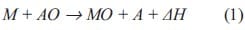
where M is a metal or an alloy and A is either a metal or a non-metal, MO and AO are their corresponding oxides, and H is the heat generated by the reaction. Due to the large exothermicity, a thermite reaction can generally be initiated locally and can become selfsustained, making their use extremely energy efficient. The self-sustained nature of thermite reactions can be adjusted by the addition of an inert diluent, as a result of this they are often used as experimental models for solid combustion studies and for pyrotechnics applications [16, 17].
Classical thermites produce small amounts of gas and have particle sizes in a range of tens to hundreds of micrometers, with their burning or reaction rate being relatively slow. Metastable Intermolecular Composites (MICs) are based on the same starting materials have particle sizes in the range of nanometres, and are also known as “superthermites”. The change in particle size induces significant changes in the energy release, kinetics and reaction propagation characteristics. If the average particle size is reduced, the rate of energy release increases due to a shorter diffusion path of the limiting reactant [16-19]. In addition, as the specific surface area increases, the number of contact points between reactants also increases and therefore the reaction rate increases.
Researchers have paid special attention to the ignition characteristics and propagation behaviour of MICs [3-6]. Pantoya et al. [5] demonstrated that the ignition time could be reduced by two orders of magnitude using Al / MoO3 mixtures with nano-sized particles (10-100 nm) instead of micron-sized particles. Furthermore, the ignition time does depend on the mixture composition and the shortest ignition time is registered in a slightly Al rich mixture. Bockmon et al. [6] studied the effect of particle size on the propagation velocity for nano-scale Al/MoO3 mixtures. Propagation velocity does increase when particle size of nano-scale Al is reduced. However, the reaction becomes independent of particle size below a specific particle diameter. In all these papers, the ignition mechanism is based on thermal initiation with a laser beam. Here the initiation by mechanical deformation is studied, a relatively new topic as shown by only recent publications in literature [13-15].
5.2. Sensitivity of energetic materials to mechanical action
One of the major problems in determining the sensitivity to initiation of an energetic material is that sensitivity depends on both the energetic material and the kind of stimulus applied. Furthermore, it is not clear in terms of which physical quantity the sensitivity of an energetic can be expressed. Often attempts are made to find an experimental method to rank energetics by their sensitivity. Various apparatus have been constructed throughout the decades being the impact tests (fall-hammer) extensively used for this issue.
The many fall-hammer tests differ mainly by the impact conditions: geometry and dimensions of the interacting elements, method of load application, etc. Some test devices to determine sensitivity to mechanical action are shown in figure 5.1. Here the main problem is the strong dependence of the tests results on the activation conditions. On the one hand, the accumulative data display the difference in energetics with respect to sensitivity and give rise to the concept of specific sensitivity as a property of an energetic material. Since it is unclear which physical quantity characterizes sensitivity, this concept is to some extend only intuitive. On the other hand, the results of numerous experiments set up under the most diverse conditions of mechanical action are not only in disagreement with the reference order, but do not display a sensitivity order at all i.e. the order varies under different conditions. It follows that one cannot speak of the sensitivity of an energetic independently of the activation conditions, or, in other words, a property such as the specific mechanical sensitivity of an energetic does not exist. The aim is then to develop a method, which for a fixed geometry and sample dimensions would be common for comparing the sensitivity of various energetics. The concepts of higher or lower sensitivity of energetics, is the outcome of much practical experience, in which a specific energetic is subjected to the most diverse mechanical actions.
In view of the strong dependence of results on the type of testing device, the concept of selective sensitivity of energetics to various types of mechanical action has become widespread. Tests in devices of types a, b, c and d (see figure 5.1) measure the sensitivity to impact, tests in devices of type e are dedicated to determine the sensitivity to friction, while devices of type f represent tests for sensitivity to needle (stab) action.
A stab action may be regarded as one of the impact tests with a small striker area. The friction tests is sometimes termed rapid shear test, indicating that the terminology (impact, friction, stab action) is of very old origin and is to some degree arbitrary. The attempt to divide the sensitivity of energetics to mechanical action into various types of sensitivity is thus equally arbitrary and questionable. Differentiation between sensitivities of explosives to mechanical action would be useful if it yielded a difference in the initiation mechanism, i.e. a distinction similar to that which distinguishes between sensitivities of energetics to mechanical action, to thermal effects, and to a shock wave.
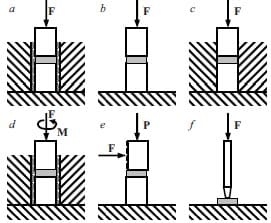
Figure 5.1: Some setups for sensitivity tests of energetic solids: devices of type a, b, c and d represent tests for sensitivity to impact, while devices of type e tests for sensitivity to friction, finally tests in devices of type f are tests for sensitivity to needle (stab) action.
In order to advance the investigation with the aim of either evaluating the specific sensitivity and determining causes of different sensitivities of energetics, or evaluating the sensitivity under given conditions, it is clearly necessary to study the mechanism of the initiation and growth of the reaction, with a well-designed test equipment.
5.2.1. Mechanism of initiation by impact
The importance of studying the mechanism of initiation by mechanical action was recognized
when developing methods of testing sensitivity of energetics. Here, the energy of the falling load (impact energy) which initiates the reaction is looked upon. Experimental evidence supports the following facts [20]:
- Different reactions are not initiated by the same impact energy, but a probability of initiation corresponds to each case.
- In most of the cases, the impact energy, which causes initiation, is insufficient to heat the sample uniformly to the ignition temperature.
- There is no relation between impact sensitivity and ignition temperature.
- The sensitivity of an energetic solid may vary for different instruments.
Two different theories of the initiation of an energetic material by impact are considered: the thermal and nonthermal theories. The latter theory (which does not fit with the second and third of the above points) postulates that chemical transformation upon impact begins as a result of molecular deformation. There are two versions of this approach: the hypothesis of critical stresses where initiation occurs when the critical stresses of hydrostatic pressure are reached, driving the molecules of the material into an unstable state; and the tribochemical hypothesis where the cause of initiation is the direct disruption of the chemical bond in the material molecules due to shear stresses. However, the nonthermal theory possesses physical inconsistencies: for example, upon deformation of organic energetic substrates, it is impossible to destroy immediately the molecules, since the energy of the intramolecular bonds is much higher than that of the intermolecular ones. Bridgman in [21, 22] examined the effect of high hydrostatic pressures on a number of explosives obtaining no initiation whereas these substances did initiate by impact at lower pressures.
According to the thermal theory, a mechanical action heats the material, resulting in a rapid chemical reaction. Since the energy of impact causing initiation is usually insufficient to heat the solid even to the reference ignition temperatures, it is clear that adiabatic compression of the explosive proper does not initiate the reaction. The thermal theory leads to the hypothesis of localized hot spots in a solid upon impact.
Considering that energetic solids contain gaseous inclusions, their adiabatic compression may produce a high temperature. It was experimentally demonstrated that compressed gaseous inclusions subjected to impact do only result in initiation when nonuniform inelastic deformation of the solid as a whole does occur. Moreover, the conditions of deformation have a significant influence on the initiation behaviour of the energetic.
A quantitative general analysis of the mechanical initiation of a reaction should include methods over the mechanics of inelastic continuous media and the theory of heat conduction, i.e. the simultaneous application of the equations of deformation and heat conduction (mechanical and chemical) with heat sources.
5.2.2. The Ballistic Impact Chamber (BIC)
The Ballistic Impact Chamber (BIC) is an instrumented version of the drop-weight impact test [9-12]. Its purpose is the low velocity impact testing of energetic materials like explosives and propellants. The fall-hammer or drop-weight impact test is usually a relatively simple test that can be performed on small quantities of energetics. It was already used in the early nineteen hundreds to assess the relative impact sensitivity of explosive materials.
Generally, the various drop-weight impact tests all aim to determine the initiation threshold. Positive and negative reactions are observed by variation of the drop height and procedures exist to arrive at the threshold within a limited number of experiments and a limited accuracy (e.g. 50 % Bruceton staircase, UN 1-out-of-6 method). A typical impact machine consists of an impactor of mass M1 and an anvil of mass M3. Often, between the impactor and the anvil is a striker of mass M2 that transfers the impact force from the drop-weight to the sample and anvil, see figure 5.2.
The physical behaviour of the drop-weight impact test can be modelled treating the dropweight, striker and anvil as a collection of mass-spring systems [9]. The energy transferred to the machine by releasing the drop-weight from a determined height, is partitioned between the elastic energy stored in the machine, the plastic energy required to deform and heat the sample to ignition, plus a small amount of energy lost in the machine during impact. As far as ignition is concerned only the plastic energy is important. Unfortunately, there is no easy way to separate elastic and plastic energies and it makes the drop-weight impact test unable to predict with accuracy the performance of energetic materials but just provides a crude ranking of sensitivity based on the Go-No Go drop-height. Moreover, this information is dominated by the stored elastic energy and therefore machine dependent.
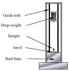
Figure 5.2: Schematic picture of the Drop-weight Impact Test machine [9].
Coffey et al. in 1995 [9] studied an impact ignition test that quantifies the amount of energy dissipated in the explosive composition. Making use of a relative soft sample of an explosive composition, which can radially expand, ignition occurs in a very early stage during impact when the stress levels are low and the sample is only undergoing deformation. This ensures that most energy transferred from the impactor goes into deforming and heating the sample and hence very little is elastic energy stored in the machine. It was observed that in most cases the energy required for ignition is still less than the potential energy of the drop-weight (= m·g·hat 50% probability of ignition), being the remaining energy stored as elastic energy or dissipated by some other ways. Coffey et al. also demonstrated that the sample size is important to allow the growth of shear stresses. It was observed [12] that ignition always occurs near the outer edge of cylindrical samples where the pressure is minimal and shear is maximal and never in regions near the centre of the sample where the pressure achieved is maximal and shear is minimal.
A thorough understanding of the parameters responsible for initiation under impact conditions is still topic of various studies. Recent calculations made by Coffey et al. [11] have demonstrated a relationship between the rate of energy dissipation and the rate of plastic deformation in crystalline solids subjected to plastic flow. In the case of explosive crystals the energy dissipated locally within the crystals during plastic deformations forms the hot spots from which chemical reactions can be initiated.
When dealing with explosives or propellants, initiation of a chemical reaction is not sufficient by itself to predict their response to an arbitrary shock or impact. The growth of the reaction in the energetic material plays an essential role in determining its response to these mechanical actions. Therefore, the object of the Ballistic Impact Chamber (BIC) test is to obtain information on the growth and extend of reaction in a simple impact test. To extend this data to more general circumstances a deep understanding of the impact ignition processes is needed.
The BIC, shown in figure 5.3, is a quasi-confined chamber, in which a striker squeezes the explosive sample against an anvil. The BIC constructed at TNO is currently equipped with two optic fibres to observe the start of reaction, a pressure gauge, a 4.5 mm diameter barrel with a lead pellet as pressure relief, and an accelerometer on the drop-weight. A 10 kg drop-weight is released from a height of 1.5 or 0.375 m, yields an impact velocity of 5.35 ± 0.09 or 2.61 ± 0.02 m·s-1, respectively, as determined in a large series of
calibration experiments. The impact of the drop-weight on the striker will give the striker a velocity of 10.7 or 5.22 m·s-1, as calculated from conservation of energy and impulse of drop-weight and striker. This velocity is initially the speed at which the solid energetic is squeezed against the anvil.
The hot gases, which may be produced from ignition, escape through the barrel accelerating the lead pellet placed inside it. Evaluating the kinetic energy of this flying pellet can provide an estimate of the extent and growth rate of the reaction.
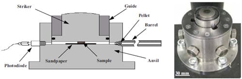
Figure 5.3: Scheme of the cross section and view of the Ballistic Impact Chamber (BIC) Test.
The time to reaction is a measure of the sensitivity of the energetic to mechanical deformation. A laser beam is aligned horizontally just above the top surface of the striker. At the moment the drop-weight hits the striker, see details in figure 5.4, the mechanical deformation starts. At the same moment, the laser beam will be interrupted and this is easily recorded with a photodiode. In the Ballistic Impact Chamber two windows are equipped with photodiodes. The first observation of light is taken as the start of the reaction. The time to reaction is defined as the difference between start of deformation and start of reaction.
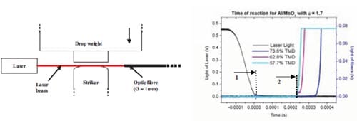
Figure 5.4: Detection impact technique used in the Ballistic Impact Chamber Tests (left) to determine when deformation does start. Typical signals obtained from a BIC test (right): (1) corresponds to the start of deformation, (2) corresponds to the start of the reaction.
5.3. Materials and sample preparation
MoO3 in powdered form is obtained from TECHNANOGY. The provided specific area, specified as a BET value of 40 m2·g-1, will give a particle size around 32 nm. Micron-sized MoO3 with a particle size of 15 µm as measured by laser diffraction, is obtained from Sigma Aldrich. Nano aluminium with a particle size of 40 nm, is obtained from TECHNANOGY as well. Mixtures are based on nano Al and nano MoO3, or nano Al and course MoO3. Powders are mixed to different fuel/oxidizer ratios r defined as:
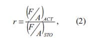
where F is the fuel mass and A is the oxidizer mass, and the subscripts ACT and STO correspond to the actual and stoichiometric compositions, respectively. The ratio r is varied from 1.0 to 1.2 and 1.7 in order to compare with results on thermal initiation presented in recent studies of Pantoya et al. [6, 19].
In addition various mixtures have been prepared including an amount of 10 wt.% Viton. The Viton binder provides mechanical strength to the pressed sample and releases gases upon reaction. While pressing the thermite samples, Viton also acts as a lubricant. It is therefore more difficult to achieve low density samples. The MoO3 particle size will affect the compaction of the mixtures, as well.
Dry powder mixtures of Al and MoO3 are suspended in an acetone solution at a ratio of 0.5 g powder to 5 ml of solvent. When using Viton, this is first dissolved into the acetone and, then, poured into the dry powder mixtures. Never more than 0.5 grams of thermite mixture is used for safety reasons and known incidents. Agglomerates are destroyed and mixing is achieved by stirring thoroughly the solution. After 10 minutes, mixing is combined with a flux of Argon, which bubbles sluggishly in the solution while stirring. The argon flux enhances the mixing process while at the same time the solution slowly dries. After 30 minutes, the acetone has evaporated almost completely. Increasing the flux of argon will allow the solvent to evaporate until a mixture of loose powder is finally obtained. Table 5.1 lists the various mixtures made.
Table 5.1: Description of the compositions differing in MoO3 particle size and fuel / oxidizer ratio. Compositions are tested in the BIC at low and high drop-weight impact velocity and at different green densities.
Loose powder mixtures are cold uniaxial pressed into preforms. Control over sample dimensions is very important when comparing the sensitivity to mechanical deformation in the BIC test, see also equation (3). Cylindrical compacts with a diameter of 5 mm and thickness of 1.2 mm are obtained by pressing in a steel die. The various applied pressures result in green densities varying from 50 up to 90 % of the Theoretical Maximum Density (TMD).
Figure 5.5: Photographs of the steel die and Al / MoO3 pellets after cold uniaxial pressing. In order to achieve highly dense greens, the upper punch of the steel die was hardened to avoid deformations while pressing.
5.4. Results and discussion
Figure 5.6 shows results for stoichiometric nano-sized Al / MoO3 mixtures subjected to two different drop-weight impact velocities (5.35 or 2.61 m·s-1) and for two ranges of sample green density. In figure 5.6, the photodiode signals are plotted as a function of the time. The signal obtained from the laser beam indicates the moment of impact between drop-weight and striker. Striker and sample are in intimate contact, and mechanical deformation of sample starts within that instant. The time of reaction is determined by the moment in which one of the photodiodes begins to capture light from a chemical reaction. The curves in dark or light tones are examples that show the start of reaction at high or low drop-weight impact velocity, respectively.
Numerical simulations of the BIC Test, for an impact velocity of 3 ms-1, are shown in figure 5.7. Results indicate that the striker, immediately after being impacted and accelerated by the drop-weight, detaches from the drop-weight due to their difference in mass. For the first 0.3 ms the striker velocity is constant and twice the drop-weight velocity. These simulation conditions are comparable to experimental results with a drop-weight impact velocity of 2.61 ms-1 presented in this chapter. The observed time to reaction, however, is always more than 0.5 ms. Therefore, an evaluation of the shear rate at the moment of reaction according to the equation [10]:
is not possible using simply h(t) = h0 – vstriker (t = 0)t. In this equation r and h are the radius and the height of the sample, v the velocity, γ the shear and t the time. Unfortunately, the real striker velocity cannot be evaluated from placing an accelerometer on the drop-weight as the drop-weight and striker detach after collision. Only a (numerical) simulation of the impact experiment, in combination with the experimentally determined time to reaction, could give the shear rate at the moment of initiation.
Figure 5.6: Typical times to reaction in stoichiometric nanosize Al / MoO3 samples at indicated drop-weight impact velocity and a high green density (up) or low density (down). Experiments are performed in duplicate.
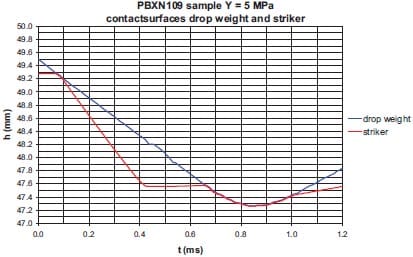
Figure 5.7: Trajectory as a function of the time of the contact surfaces
of drop-weight and striker. The velocity of the drop-weight prior to impact is 3 m·s-1. Although simulations are run considering the explosive PBXN109, initially no influence of the physical or mechanical properties of the material is observed [14].
Experimental results will be discussed regarding: 1) the effect of drop-weight impact velocity, 2) green density or remaining porosity, 3) addition of Viton binder, 4) MoO3 particle size, and 5) fuel/oxidizer ratio, on the sensitivity of the Al / MoO3 mixtures towards mechanical deformation.
Impact velocity – Figure 5.6 indicates that the time to reaction decreases when increasing the impact velocity. A typical time to reaction for a stoichiometric Al / MoO3 mixture at high drop-weight impact velocity is ˜ 0.4 ms, while at low drop-weight velocity a typical time to reaction is ˜ 1.0 ms. When higher impact velocities are applied, larger shear rates are induced in the samples, resulting in a faster initiation.
Green density / Porosity – In figures 5.8 and 5.9, the time to reaction is plotted for the various Al / MoO3 mixtures. Figure 5.8 covers the results with micron-sized MoO3 and figure 5.9 the results with nano-sized MoO3. The timescales corresponding to initiation by high and low impact velocity are clearly separated.
For the 5.35 m·s-1 impact velocity no significant correlation with porosity is observed. In a previous series of tests [14] with the same impact conditions, it is concluded that sensitivity is enhanced by porosity. The limited number of experiments yielded that premature conclusion.
For the 2.61 m·s-1 impact velocity, however, significant changes in time to reaction can be measured. A clear trend is seen for the mixtures without Viton binder. The time to reaction increases with increasing porosity. Actually, the sensitivity of the mixture decreases with increasing porosity.
The porosity is expected to have an effect on the sensitivity to initiation in the BIC test as deformation is controlled by the mechanical properties of the material. In the test set-up there will be a compaction in the vertical direction. The compaction will depend on initial porosity. Although the initial striker velocity is constant and imposed by the falling drop-weight, a resistance to compaction is building up in time. The resistance to compaction will be larger for low porosity. Even without considering a constant volume of the impacted and porous energetic mixture, there must be a radial expansion of the thermite mixture. One should note that the constant volume approach is one of the assumptions in the derivation of equation (3). The radial expansion is accompanied by shear deformation as well, as there is a contact surface between sample and striker and between sample and anvil with sandpaper. Note that the sandpaper is added to obtain reproducible results [9, 10]. The shear is expected to increase with decreasing porosity, and this effect will be stronger for a mixture with polymeric binder. Although the deformation of a porous mixture will be complex, the shear rate is expected to raise faster in low porosity samples. If shear rate is a controlling parameter in mechanical initiation, then time to reaction will decrease with decreasing porosity in the BIC test.
Addition of a binder – It has been mentioned that shear is expected to increase by addition of a polymeric binder. In the experiments in figure 5.8 more or less the same time to reaction is observed for samples with or without Viton binder, when comparing results at the same porosity and stoichiometry. However, in figure 5.9, the time to reaction is always shorter in mixtures containing Viton binder. This indicates that the effect of Viton addition is not independent of the MoO3 particle size. Furthermore, in mixtures with Viton the time to reaction is not or hardly dependent upon porosity.
MoO3 particle size – The difference between figures 5.8 and 5.9 is the MoO3 particle size. Both figure 5.8 and 5.9 indicate that mixtures with micron and nano-sized MoO3 present comparable times to reaction. Mixtures with finer particles in general show faster kinetics and times to reaction are expected to reduce. Only with the presence of Viton in mixtures with nano MoO3 a noticeable faster reaction is observed.
Fuel/Oxidizer ratio – Results shown in figure 5.8 and 5.9 do not indicate any clear effect of the fuel/oxidizer ratio for either high or low impact velocity with the exception of fuel rich Al / MoO3 (r = 1.7) at a low drop-weight impact velocity and no binder. Pantoya et al. has experimentally observed that the ratio of Al / MoO3 can influence the ignition mechanism [5] when a thermal stimulus is applied, and a 20 % fuel rich mixture (r = 1.2) has the shortest ignition time and the highest combustion velocity. It could also be expected that the ratio of fuel/oxidizer does affect the tendency to ignite due to high deformation rates as the structural properties of the material and hence the resistance to shear, change when varying the composition. However, results here presented do not show any evidence of that. A further study on Al / MoO3 mixtures as well as a better understanding of the initiation mechanism is needed in order to find an explanation to this phenomenon.
In a parallel study at TNO it has been demonstrated that a composition based on the same nano Al, micron-sized MoO3 and Viton ingredients, when pressed to a density of 95%TMD, can be accelerated from a gun without disintegrating, and deform and initiate on impact at a steel plate. The determined initiation threshold for a sample with 12.6 mm of diameter and a height of 22 mm lies in between 700 and 1400 m·s-1 and shows the applicability of MICs as an energetic fragment [14]. The reaction at these high impact velocities is noticed within a few microseconds after impact.
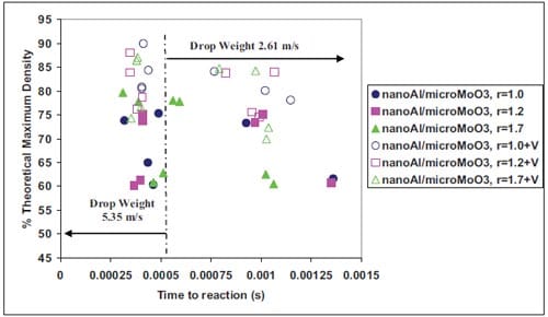
Figure 5.8: Time to reaction in the BIC for thermite samples with different porosity (%TMD), fuel/oxidizer stoichiometry (blue, purple and green), addition of Viton binder (solid or open symbols with “V” meaning Viton), and at indicated drop-weight impact velocities. The thermite is based on nanometric aluminium and micronsize molybdenum trioxide.
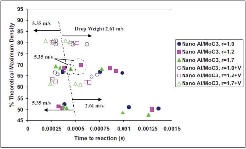
Figure 5.9: Time to reaction in the BIC for thermite samples with different porosity (%TMD), fuel/oxidizer stoichiometry (blue, purple and green), addition of Viton binder (solid or open symbols with “V” meaning Viton), and at indicated drop-weight impact velocities. The thermite is based on nanometric aluminium and molybdenum trioxide.
5.5. Conclusions
- Reactive materials research is still in a very early stage of exploration and development.
- The chemical energy released by thermites, intermetallic mixtures or MICs is usually tunable and can be used for different purposes depending on application. Energetic fragments make use of this feature.
- A reactive fragment delivers kinetic and chemical energy being the damage greatly increased. The chemical reaction is initiated due to mechanical deformation at impact.
- Assuming shear rate is the parameter that controls initiation, mechanical deformation and sensitivity to impact of MICs can be studied in the Ballistic Impact Chamber Test.
- The sensitivity of pressed Al / MoO3 mixtures towards mechanical deformation has been studied, using the Ballistic Impact Chamber. In particular, the effect of green density / porosity, a polymeric binder, MoO3 particle siz
e and fuel / oxidizer ratio has been looked at. - The drop-weight impact velocity had to be lowered to see the effect of these parameters on sensitivity.
- The sensitivity towards mechanical deformation is reported as time to reaction, and evaluation of shear rate at the moment of initiation has not been possible.
- Samples with low porosity will react faster, as shear and shear stress increase with decreasing porosity. Also the addition of the Viton binder to nanometric mixtures of Al and MoO3 enhances the initiation which can be attributed in the same way to a change in mechanical properties and increase of shear and shear stress.
- The change of micron-sized to nano-sized MoO3 leads to an improved sensitivity only, in the presence of the Viton binder.
- Hardly any effect of fuel-oxidizer ratio on mechanical sensitivity is observed here, whereas in thermal initiation of similar mixtures, an optimum sensitivity is found depending on the fuel-oxidizer ratio.
5.6. References
- Field J.E.: “Hot Spot Ignition Mechanisms for Explosives”, Acc. Chem. Res., 25 (1992), pp.489-496.
- Goldschmidt H., Iron Age, 82 (1908), p.232.
- Plantier K.B., Pantoya M.L., and Gash A.E.: “Combustion Wave Speeds of Nanocomposite Al/Fe2O3: the Effects of Fe2O3 Particle Synthesis Technique”, Combust. Flame, 140 (2005), pp.299-309.
- Asay B.W., Son S.F., Busse J.R., and Oschwald D.M.: ”Ignition Characteristics of Metastable Intermolecular Composites”, Propell., Explos., Pyrotech., 29(4) (2004), pp.216-219.
- Pantoya M.L., and Granier J.J.: “Combustion Behavior of Highly Energetic Thermites: Nano versus Micron Composites”, Propell., Explos., Pyrotech., 30 (2005), pp.53-62.
- Bockmon B.S., Pantoya M.L., Son S.F., Asay B.W., and Mang J.T.: “Combustion Velocities and Propagation Mechanisms of Metastable Interstitial Composites”, J. Appl. Phys., 98 (2005), pp.64903-1:7.
- Powers J.M.: “Thermal Explosion Theory for Shear Localizing Energetic Solids”, Combust. Theor. Model., 3 (1999), pp.103-122.
- Bardenhagen S.G., Brackbill J.U., and Sulsky D.L.: “Shear Deformation in Granular Material”, Proc. 11th Int. Detonation Symp., Ed. Peiris S., ONR 33300-5 (1998), pp.547-555.
- Coffey C.S., and DeVost V.F.: “Impact Testing of Explosives and Propellants”, Propell. Explos. Pyrotech., 20 (1995), pp.105-115.
- Namkung J. and Coffey C.S.: “Plastic Deformation Rate and Initiation of Crystalline Explosives”, AIP Conf. Proc., Ed. Furnish M.D., Horie Y. and Thadhani N.N., American Institute of Physics, ISBN 0-7354- 0068-7, 620 (2002), pp.1003-1006.
- Coffey C.S. and Sharma J.: “Initiation of Crystalline Explosives due to Energy Dissipated during Plastic Flow”, Proc. 11th Int. Detonation Symp., Ed. Peiris S., ONR 33300-5 (1998), pp.751-757.
- Zerilli F.J., Guirguis R.H. and Coffey C.S.: “A Burn Model Based on Heating due to Shear Flow: Proof of Principle Calculations”, Proc. 12th Int. Detonation Symp., Ed. Peiris S., 2002, online paper in https://www.intdetsymp.org/detsymp2002/.
- Son S.F., Foley T.J., Sanders V.E., Novak A.M., Tasker D.G., and Asay B.W.: “Overview of Nanoenergetic Material Research at Los Alamos”, in Multifunctional Energetic Materials, Proc. Mater. Res. Soc. Symp., 896 (2006), 0896-H03-03.
- Meuken B., Martinez Pacheco M., Bouma R., and Katgerman L.: “Shear Initiated Reactions in Energetic and Reactive Materials”, in Multifunctional Energetic Materials, Proc. Mater. Res. Soc. Symp., 896 (2006), 0896-H06-06.
- Ames R.G.: “Energy Release Characteristics of Impact-Initiated Energetic Materials”, in Multifunctional Energetic Materials, Proc. Mater. Res. Soc. Symp., 896 (2006), 0896-H03-08.
- Wang L.L., Munir Z.A., and Maximov Y.M.: “Review Thermite Reactions: Their Utilization in the synthesis and Processing of Materials”, J. Mater. Sci., 28 (1993), pp.3693-3708.
- Munir Z.A.: “Synthesis of High Temperature Materials by Self-Propagating Combustion Methods”, Am. Ceram. Soc., 67 (1988), pp.342-349.
- Tomasi R., and Munir Z.A.: “Effect of Particle Size on the Reaction Wave Propagation in the Combustion Synthesis of Al2O3-ZrO2-Nb Composites”, J. Am. Ceram. Soc., 82 (1999), pp.1985-1992.
- Granier J.J.: “Combustion Characteristics of Al Nanoparticles and Nanocomposite Al+MoO3 Thermites”, Doctoral Thesis, Texas Tech University, 2005.
- Afanas’ev G.T., and Bobolev V.K.: “Initiation of Solid Explosives by Impact”, Ed. Israel Program of Scientific Translations, Jerusalen, 1971.
- Bridgman P.W.: “ Effects of High Shearing Stress Combined with High Hydrostatic Pressure”, Phys. Rev., 48 (1935), pp.825-847.
- Bridgman P.W.: “The Effect of High Mechanical Stress on Certain Solid Explosives”, J. Chem. Phys., 15 (1947), pp.311-313.
Chapter Six
Electrostatic Discharge Initiation of Reactive Materials1
Energetic materials are susceptible to spark and/or impact, requiring adequate safety measures. In this chapter, experiments are focus on determining the spark sensitivity of various energetic compositions. The studied energetics comprise intermetallic and thermite mixtures. Both intermetallics and thermite mixtures hardly produce gases, and reactants have to be in close proximity in order to be sufficiently sensitive to initiation. At the same time, the reaction velocity is increased by the decrease of the distance between reactants. In a number of applications (initiators, delay charges, reactive fragments) both the sensitivity of the reacting mixture and the speed at which heat is released are important parameters.
Electrostatic discharge measurements are performed with a dedicated apparatus in which the initiation threshold will not only be specified in terms of the capacitor energy, but also in terms of the energy dissipated in the spark through the energetic material. The electrostatic discharge sensitivity of the tested materials strongly depends on the particle size but on mixture preparation techniques as well. Mechanical treatments like alloying by ball milling processes will enhance sensitivity. Probably it is the higher sensitivity that will increase the reaction rate of the Ti + C mixtures in Self-sustained High-temperature Synthesis of TiC. However, finer Ti + C mixtures do present a higher sensitivity to ESD than ball milled powders. Both Ti + C mixtures are still less reactive to electrostatic discharge ignition than the (ultra)fine or nano-sized thermites Al / MoO3, Al / Fe2O3, Al / Bi2O3, Al / Ti or Ti / xB considered as well in this chapter. The sensitivity of nano-sized Al / MoO3 mixtures decreases when the nano-sized MoO3 powder is substituted by coarser MoO3 powder. However, this feature is lost in the presence of the nitrocellulose as energetic binder. Nano-aluminium powder is less sensitive to ESD than Al / MoO3 mixtures, and therefore it is believed that the initiation thresholds correspond to the thermite reaction and are not attributed to aluminium oxidation in air. The presence of Al2O3 in Al / Fe2O3 thermites does influence greatly their sensitivity to ESD initiation. When the Al2O3 content in aluminium is lower than 31.9 wt.%, this thermite is the most sensitive mixture to spark ignition. Stoichiometry is also an important parameter to be considered in ESD tests. Stoichiometric mixtures are more reactive to ESD than non-stoichiometric mixtures. Finally, it is observed that the initiation behaviour is different for short or long spark pulses in pyrotechnic mixtures rather sensitive to ESD initiation.
An introduction into the susceptibility of energetics to spark initiation is given in paragraph 6.1. The determination of the electrostatic sensi
tivity of energetics is mentioned in this paragraph as well. In paragraph 6.2, the electrostatic discharge apparatus and the preparation of the various energetic mixtures are described. Results together with a discussion on morphology and spark sensitivity of intermetallic and thermite mixtures are reported in paragraph 6.3. Finally, conclusions are drawn in paragraph 6.4.
6.1. Introduction
Initiation of energetics can in general be due to conversion of mechanical, chemical, electrical, or other energy, followed by an exothermic chemical reaction which generates additional heat and, thereby, accelerates the reaction rate. If a sufficiently high temperature is attained within a sufficient large volume of the energetic, the chemical reaction and heat release processes will continue to ignite the rest of the volume. Electrostatic discharge (ESD) sensitivity is an important parameter in the safe handling of energetic materials since electric sparks may occur in handling situations.
The role of safety testing is to determine whether there is a large probability that energy from likely sources, i.e. impact, friction, spark discharge, etc., will ignite an energetic material. Such a determination is convenient when a safety test is mainly controlled by a single characteristic of an energetic material [1]. In that case, the test data will be highly correlated with that material property, and thus that property can be used to predict the safety performance of the material to that particular hazard. The usual situation, however, is that a safety test which is usually defined to simulate some specific hazard, such as ignition by spark discharge, will be controlled by several characteristics of the energetic.
Electrostatic discharge incidents have been studied for some time, and there is reasonable agreement on three models describing these phenomena [2]: the human body model, the machine model, and the charged device model. The human body model simulates the ESD event when a person charged either to positive or negative potential, contacts with another body at a different potential. The charged device model simulates the ESD event wherein a device charges to a certain potential, and touches with a conductive surface at a different potential. The machine model simulates the ESD event that occurs when a part of an equipment or tool contacts a device at a different potential. Human body and charged device model are considered to simulate better real situations than the machine model. Each of these models possesses its equivalent RLC circuit with a determined value of resistance, inductance and capacitance with respect to its surroundings, and hence different time constant values (τ = RC).
In order to determine the ESD sensitivity of energetic powder mixtures, usually the Human body or the Machine Model are used (with its variants). Several factors have been identified as contributing to the sensitivity of an energetic material to initiation by ESD [3]. Properties such as resistivity, relative permittivity and breakdown voltage are of principal importance and each of these is influenced by a range of external factors including temperature, pressure and relative humidity. However, whether or not initiation occurs in a given situation will also depend upon local effects such as the nature of the electric field and the rate at which energy is deposited into the energetic material.
During the early 1940’s the Explosives Division of the U.S. Bureau of Mines investigated the hazards associated with explosives for electrostatic discharge ignition [1]. Years after, the ESD apparatus was redesigned. In an issued report it was determined that the best single criterion of the ESD sensitivity of a material was to subject the material to a spark from a capacitive discharge. The total energy initially stored on the capacitor was used as a measure of the energy discharged into the energetic sample. To eliminate energy losses in an apparatus, which rapidly switched the high voltage, the charged capacitor was switched into contact with a needle electrode when the sample-to-electrode spacing was still large, and then the electrode was rapidly moved towards the sample to a position where its distance from the other electrode was closer than necessary for spontaneous breakdown.
Samples were tested in two configurations: unconfined samples were placed in a shallow depression in the top of a steel block; partially confined samples were placed inside a glass tube with a grounded steel plug at one end and the moving needle entering the tube from the opposite end. Generally, to vary the discharge energy, capacitors of different values were used with the charging voltage held constant at 5 kV, no series resistance was used in the discharge circuit. Steel phonograph needles were used for electrodes. Significant differences were measured between unconfined and partially confined 50 mg samples. A tabulation of the highest ESD energy at 5 kV for which there is still a zero ignition probability was given for several energetic materials both unconfined and partially confined. Several trends in ESD sensitivity were observed from the tests:
- Large particles ignite less readily than small particles.
- Except for primary explosives, the degree of confinement usually has a marked effect on the ease of ignition and completeness of combustion.
- The ignition energies for unconfined samples of finely ground secondary high explosives are invariably less than for the same samples tested under confinement.
- The ignition of unconfined secondary high explosives is apparently due to explosions of fine dust dispersed in the air by the spark.
- Metal powders are more sensitive when tested unconfined.
- Black powder is much more sensitive when tested under confinement.
An estimate of the magnitude of electrostatic discharge that may arise from the human body was also made. Capacitance values between 0.1 and 0.4 nF were measured for various personnel. A value of 10 kV was arbitrarily selected as the likely personnel charging potential, giving a stored energy value of 15 mJ from the total energy formula E = 1/2·C·V2, where C is the capacitance value in farads and V is the charging voltage.
Kirshenbaurd et al. [4] during the 1970’s presented an improved version of the approaching needle electrode apparatus developed by the Bureau of Mines. Their test procedure was divided into two parts: a screening test to distinguish between primary and secondary main-charge explosives, and a test to rank or compare energetic materials in the primary explosives category. In the screening test, a material was assessed using a discharge with no series resistance at a fixed energy of 20 mJ. Materials that ignited at this level were considered very sensitive and placed in the primary explosives category. Samples were usually unconfined and placed in a depression in a metal-grounded electrode. The effects of discharge parameters on the minimum ignition energy were studied extensively.
Larson et al. [5] subsequently continued the development of the ESD test, mainly in establishing an improved sample confinement configuration using lead foil and performing additional studies on secondary explosives. Particle size, sample weight, electrode material, series resistance, sample temperature, voltage, free volume in the sample holder, and degree of confinement were systematically studied. The type of confinement chosen in this case eliminated subjectivity in operator judgement of Go-No Go in testing.
Not long ago, Fisher [6] developed an improved model and apparatus for simulating a worstcase scenario for spark discharge from a static charge build-up on a person. His work determined that a person could have a very short duration but high current discharge combined with a slower discharge. The test apparatus for simulating this situation gives a v
ery short high current transient followed by a longer duration discharge, which is achieved by combining the discharges of two energy storage capacitors through circuits with different time constants. ESD testing using this type of discharge is more likely to ignite energetic components (mainly due to the high current in the initial spike) than the single pulse.
It should be noticed that small-scale sensitivity tests do not necessarily provide exact scientific values, but rather relative ones that depend on the testing conditions employed. The Pershing accident in January 1985, demonstrated that small-scale ESD tests either do not scale or that they neglect some important parameters [5]. The accident was officially attributed to an ignition of the rocket propellant by an electrostatic discharge. This energetic did not show any adverse behaviour in the small-scale ESD tests used by propellant manufacturers. Most of the small tests will not scale to either larger circumstances or slightly different stimuli, so their results must be used with caution. Another problem with sensitivity tests is the demand for standardization. Standardization in principle is good, but may lead to blind acceptance of numbers; as the experimental results have a limited value depending on the application it takes to represent.
6.1.1. Determination of electrostatic discharge sensitivity
Standard ESD tests classify the susceptibility of an energetic material to ESD in terms of the energy available from a charged capacitor. However these tests are designed as screening tests and tend to categorise energetic materials into fairly broad bands according to their sensitivity to ESD. Additionally, the initiation energy is usually quoted in terms of the energy stored within the capacitors prior to discharge. This may be very different from the energy of the spark, which the sample experiences.
The sensitivity of a mixture to spark ignition also depends on the duration of the spark. Depending on the prevailing initiation mechanism of the substance tested, the ESD test is carried out at undamped discharge (short duration spark) or damped discharge conditions (long duration spark). Undamped discharge conditions are typical of substances with prevailing initiation stimulus by a shock wave. However, energetic materials initiated predominantly by a relatively long-term heat impulse, are tested under damped discharge conditions. Typically, high explosives tend to require a high power spark of short duration for ignition whereas primary explosives and pyrotechnics require a spark of longer duration at a lower power [4, 5, 7-10]. According to [5], two types of reaction may be occurring depending upon the spark energy. At low energies, the amount of reaction is proportional to the energy. When the energy is increased beyond a certain value, a self-sustained reaction occurs. In this reference, the energy refers to the energy stored in the capacitor prior to discharge. Therefore, to study the sensitivity of energetic materials purely in terms of the energy required for ignition without reference to the duration of the spark, has little scientific meaning. There is a need to refine current test methods in order to determine more accurately the energy and duration of the spark required for ignition of the sample.
In order to determine the spark sensitivity of energetic materials, it is useful to describe first the electrostatic discharge phenomenon [11]. In electric spark tests, the samples receive an electric discharge that first crosses an air column. The breakdown phase is characterized by very high peak values of voltage and current and an extremely short duration (1-10 ns). Already, at a very early stage, a cylindrical channel develops together with a rapid temperature rise to 60000 K. The energy supplied is transferred almost without loss to the plasma where it is stored by dissociation and ionization. The pressure jumps to 200 bar causing thus the emission of an intense shock wave and the subsequent expansion of the plasma channel. Thus, the temperature drops as a function of time and the potential energy i.e. dissociation and ionization, is reconverted into thermal energy. The energy portion originally removed by the shock wave (30 %), will be recovered by the plasma, as it finally expands throughout the region where the major part of the shock energy has been absorbed. The arc voltage is very low (< 100 V) although the current may be as high as the impedance of the external circuit permits. Only 1 % of the air molecules are ionized but the degree of dissociation may be quite high in the central region of the discharge. The arc expands mainly due to heat conduction and mass diffusion. Due to continuous energy losses, the equilibrium kernel gas temperature will be limited to 6000 K. Temperature and degree of dissociation decrease rapidly with increasing distance from the axis of the electrodes. An increase in breakdown energy does not manifest itself in higher kernel temperatures. Instead, the channel diameter increases, causing a larger activated gas volume. The spark initiation process is divided in two stages. In the first stage, the energetic is heated to a critical temperature (thermal explosion temperature) while in the second stage, the heated material self ignites. Auzanneau et al. [11] studied the energy transferred to the sample based on these two stages. However, most ESD tests define the sensitivity of a sample in terms of the energy Ecap discharged from a capacitor [10, 12]:
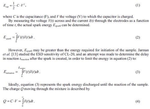
This chapter describes the result of testing intermetallic and thermite type energetic mixtures in a spark test apparatus for various spark durations. In particular, the thermite Al / MoO3, for different particle sizes, with and without nitrocellulose is studied in this paper.
6.2. Experimental procedure
In this paragraph, the electrostatic discharge apparatus as well as the various intermetallic and thermite compositions to be tested are described.
6.2.1. Electrostatic discharge apparatus
An electrostatic discharge apparatus consists of two main parts: the high voltage block containing a high voltage source, storage capacitors, damping resistors and a high voltage switch; and the test chamber in which the electrostatic spark can be safely discharged through the test sample, see figure 6.1.
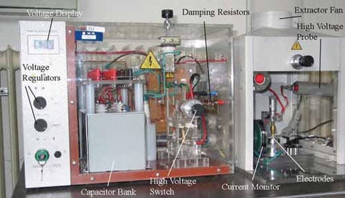
Figure 6.1: Photograph of the electrostatic discharge apparatus used for the various experiments.
For the apparatus shown in figure 6.1, a transformer and voltage multiplier increase the voltage to between 3.2 and 10 kV, which is supplied to the capacitors. Five capacitors are included within the test apparatus with approximate values of 5, 15, 30, 100 and 200 nF. In addition, capacitors with values of 62, 92, 142 and 242 pF have been incorporated to the capacitor bank in order to test the most sensitive mixtures. These capacitance values include 42 pF of the connecting cable. The capacitors are connected to the HV supply by pulling on a spring-loaded mechanical switch. Without any damping resistors connected to the circuit, the discharge circuit will produce an attenuated oscillating discharge, with a frequency f given by:
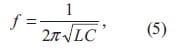
where L is the inductance of the discharge circuit, and C is the capacitance. The discharge produces a spark with duration of a few microseconds only.
Depending of the reactivity of the energetic mixture, a spark of longer duration may be required. This can be achieved by connecting a damping resistance R into the discharge circuit
. The time constant for the capacitor discharge is then given by τ = RC.
For the tests described in this chapter, the value of R is 10 kΩ which produces a spark of a few milli-seconds duration using capacitors of nanofarads. When capacitor values of picofarads are considered, a spark duration of a few micro-seconds is achieved. Subsequent tests used no damping resistances at all.
The high voltage supply is connected to a micrometer, which holds the anode of the spark gap. The anode and cathode are made of steel, surrounded by rubber tubing. The cathode tubing extends 1 mm above the cathode to hold the test sample. The volume of sample is 4.5 mm3 and the spark gap length close to 1 mm. A fiber optical detector based on a United Detector Technology photo diode (Model F0-02-400) measures the light produced by reaction of the sample, see figure 6.2.
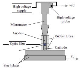
Figure 6.2: Scheme of the spark gap setup without damping resistances used for the various experiments.
6.2.2. Materials
The sensitivity of energetic powder mixtures depends on the intrinsic properties of the starting materials. Initiation properties can be varied systematically by introducing defects and dislocations in the unit lattice of the material, i.e. by ball milling techniques, or by decreasing the particle size of the powder mixture (increasing thus the surface energy).
Furthermore, the quality of mixing is expected to influence the ESD sensitivity of energetic powder mixtures. A finely dispersed powder mixture assures that atoms of different starting elements are in intimate contact and thus react easier and faster than in non-homogeneous mixtures where migration of atoms must occur in order to achieve reaction between the starting elements.
Before determining the ESD sensitivity of energetic materials, the morphology as well as the homogeneity of the powdered mixtures is determined by performing a SEM study of the powders and powder mixtures to be tested.
Experiments on the ESD sensitivity are initially focused on powder mixtures of Ti + C and the thermite Al / MoO3.
High-purity (99.7%) titanium powder is obtained from Gimex and graphite powder from Sigma-Aldrich Chemie. The code BM, attributed to the titanium-carbon mixtures, indicates that the powder mixtures are subjected to various ball milling processes in order to increase their reactivity. Parameters such as milling time, number and size of grinding balls and amount of material are successively varied for every titanium and graphite mixture.
Amounts of MoO3 in powdered form are obtained from TECHNANOGY. In this case, information about the particle size is given by the specific area. For a BET value of 40 m2·g-1, the particle size is around 32 nm. ALEX® nanoaluminum obtained from Argonide is used to make the Al and MoO3 mixtures. Furthermore, to prevent formation of clusters and obtain as much as possible homogeneous mixtures, a certain amount of nitrocellulose (NC) is added to the Al / MoO3 powder mixture. The Al / MoO3 / NC mass ratio is taken from a recent paper of Naud et al. [14], where the oxide content of the aluminium has been determined experimentally in order to compensate for this partial oxidation by adding more aluminium. Because of the similar particle sizes the same composition is used. In order to observe the influence of particle size on ESD sensitivity of the Al / MoO3 mixtures, in two of the mixtures the nano MoO3 has been replaced by coarse, micronscale MoO3. Table 6.1 lists the specifications of the various tested samples.
In addition, a new series of experiments is performed in which the ESD sensitivity of the mixtures Ti + C with reduced particle size, Ti + xB, Ti + 2Al, and the thermites Al / Fe2O3 and Al / Bi2O3 is determined. Here mixtures are made varying the particle size of some of the reactants as well as the degree of oxidation or passivation in the case of nano aluminium powders. The last rows of table 6.1, starting from sample 04PEM170, are dedicated to the materials used for the second series of experiments.
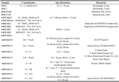
Table 6.1: List of specifications for the Ti + C, Ti + xB, and Ti + 2Al mixtures as well as the thermites Al / Fe2O3 and Al / Bi2O3 tested to determine their ESD sensitivity.
6.3. Results and discussion
6.3.1. Morphology and homogeneity of mixtures
Figure 6.3 is a scanning electron micrograph of the titanium and graphite mixture BM7. The lightest particles correspond to titanium while the darkest ones correspond to graphite. One can observe the deformation process that initial spherical particles have suffered during ball milling. The particle size after ball milling is still larger than 20 µm after processing in most of the mixtures.
Figure 6.4 shows a detail of the particle morphology of sample BM17. The deformation process in the attrition mill has been even more intense compared to BM7 using the same starting materials. The shape of the particles has been changed from spheres to plates after attrition milling.
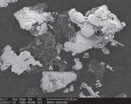
Figure 6.3: Scanning Electron Microscopy image of sample BM7 a Ti + C powdered mixture after 75 hours on a rollerbank.
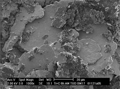
Figure 6.4: SEM micrograph of sample BM17 a Ti + C powder mixture after 6 hours on an attrition milling.
Figure 6.5 represents a scanning electron micrograph of the ALEX® aluminium in a mixture with MoO3. Here, the spherical morphology of the particles together with the narrow particle size distribution is remarkable and even more important is the fact that separate clusters of aluminium and molybdenum trioxide have been found, indicating the importance of sample preparation in order to obtain well-dispersed reactants.
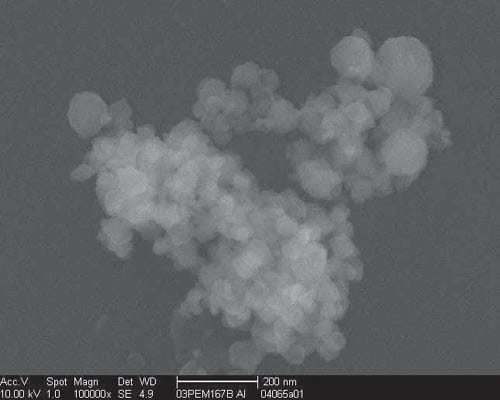
Figure 6.5: SEM micrograph of an ALEX® nano aluminium cluster in an Al/MoO3 powder mixture (03PEM167b).
6.3.2. Experimental results on electrostatic discharge sensitivity
Figure 6.6 presents the measured voltage profiles with and without 10 kO series resistance added, for sample 04PEM25 containing nano Al, nano MoO3 and NC, see composition in table 6.1. Both voltage profiles correspond to positive experiments (ignition) near the initiation threshold. With these low energy levels, the reaction time is about 200-300 µs and much longer than the application of the spark. Figure 6.7 gives the measured voltage and current profiles of similar samples as in figure 6.6. However, the applied energy is far above the initiation threshold and reaction is completed during the electrostatic discharge. The long duration of reaction compared to the spark is the reason why it is difficult to obtain a distinct initiation threshold. Furthermore, this behaviour is different from the initiation of CL-20 where near the threshold the reaction is driven by the duration of the spark [13].
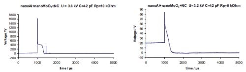
Figure 6.6: Voltage (V) as a function of time (µs) for a nano-sized Al / MoO3 / NC mixture during a long pulse (left) and a short pulse (right).
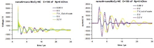
Figure 6.7: Voltage (V) and current (A) for va
rious initial capacitor voltage values as a function of time (µs) for the nano-sized Al / MoO3 / NC mixture during a short pulse, left and right respectively.
Figure 6.8 represents the voltage and current measured for different initial voltage values for samples 03PEM167b and 03PEM167, i.e. Al / MoO3 or Al / MoO3 / NC mixtures respectively. It can be observed that 1) the initial current is always nicely controlled by capacitor voltage and series resistance and, 2) that the current decreases with time constant RC. The figures show that there is a secondary discharge within the ESD apparatus. In figure 6.8 there is seemingly a secondary discharge in the system. Due to the mechanical and electrical configuration of the switch, no possible further discharge can be produced by the ESD apparatus once the first discharge is achieved. This means, that the recharge and ulterior discharge is an intrinsic and not controllable response of the material. It seems that there is a different behaviour depending on the presence of nitrocellulose. With nitrocellulose there always is a clearly separated secondary discharge.

Figure 6.8: Voltage (V) and current (A) for various initial voltage values (U) as a function of time (ms) for the nano-sized Al / MoO3 / NC mixture (up) and for the nano-sized Al / MoO3 mixture (down) both during a long pulse.
Table 6.2 summarizes the threshold ESD sensitivities of the intermetallic and thermite mixtures. The ESD sensitivity is evaluated in terms of the capacitor energy and the minimum spark energy to cause ignition of the sample, as calculated from the oscilloscope traces of voltage and current. It is especially remarkable the broad range in spark energy i.e. from 2.5 to less than 3·10-6 J, for the intermetallic and thermite mixtures tested. This anticipates serious safety problems to handle these energetic mixtures.
The ESD sensitivity results strongly depend on the powdered material properties such as particle size, morphology and degree of dispersion. In earlier work [15] it has been shown that the differences in preparation of Ti + C mixtures, i.e. different ball milling processes, do influence the reaction rate in Self-sustained High-temperature Synthesis. It was shown that mixtures subjected to longer milling times and/or more powerful milling techniques do present faster reaction times. ESD measurements indicate that not all the ball milled Ti + C mixtures are sensitive enough to determine their initiation threshold with the current ESD apparatus. The mixtures BM17 and BM18, which have been prepared by the very powerful attrition mill processing technique, are the most sensitive towards ESD when compared to the other Ti + C ball milled mixtures. It is shown therefore that by a proper mechanical treatment, one may enhance the sensitivity of a reactive mixture. In this particular case, the capacitor energy has been lowered at least by a factor four.
Table 6.2 indicates that the nano Al / MoO3 mixtures are the most sensitive to ESD. For most of the Al / MoO3 mixtures, the ESD thresholds have been obtained. Only sample 04PEM27, which is made with coarse MoO3, shows less reactivity as the specific surface decreases compared to the nano Al / MoO3 mixtures. These results demonstrate that the reactant particle size largely influences the ignition mechanism of energetic mixtures. Samples 04PEM27 and 04PEM29 are made with nano Al and coarse MoO3. However, the presence of nitrocellulose increases the reactivity of the mixtures. This phenomenon can also be observed in sample 04PEM25 with nano Al and nano MoO3. Here the ESD threshold is lower than the equivalent sample without nitrocellulose for both short and long pulse duration.
ESD initiation of the nano-aluminium itself has been carried out in order to know the contribution of aluminium oxidation in air to the sensitivity and reaction of the thermite mixture. The initiation energy of the nano-aluminium (04PEM33a) is about three orders of magnitude larger than the initiation energies of the nano Al / MoO3 mixtures. This is a strong indication that the measured initiation energies correspond to the thermite reaction.
Results for mixtures containing nano Al and nano MoO3 or nano Al, nano MoO3 and nitrocellulose, samples 03PEM167 and 03PEM167b respectively, are not included in table 6.2 due to the fact that their ESD sensitivity could not be determined by the apparatus at that time. The capacitor bank of the ESD apparatus was then modified in order to obtain ESD thresholds for these Al / MoO3 nano mixtures. Experiments performed for sample 03PEM167b with a new capacitor bank are represented in table 6.3. The energy producing initiation of the sample in 50 percent of the trials cannot be determined for an initial voltage of 3.2 kV and a capacitor value of 5.1 nF, and always an ignition is observed. Due to the high reactivity shown by these mixtures, other capacitor with even lower capacitances should be included in the ESD apparatus.
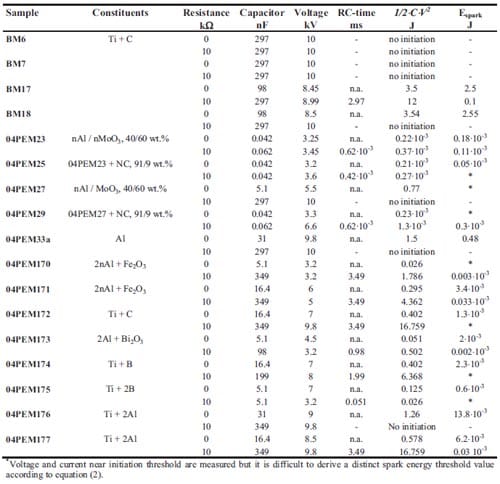
Table 6.2: ESD sensitivity results for the various studied mixtures.
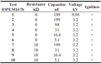
Table 6.3: ESD sensitivity tests for sample 03PEM167b. The ESD threshold sensitivity cannot be determined for these values of initial voltage and capacitance due to the high reactivity of the mixture.
Sample 04PEM175, micron-sized Ti and B powders both in stoichiometric ratio, is the most sensitive intermetallic mixture tested. Actually 04PEM175 is so sensitive that the reproducibility in sensitivity threshold is again difficult to measure and/or the ESD equipment has difficulty in reproducibly generating a low Espark. Sample 04PEM176, a micron-sized 2Al + Ti powder mixture, it is more sensitive than the Ti + C ball milled mixtures but less than the sample 04PEM172, a Ti + C mixture containing fine Ti and C powder.
The fact that the ESD sensitivity depends on the mean size of the reactants used is again evident by comparing samples 04PEM176 and 04PEM177, containing both micron-sized Ti and micron-sized Al or nano-sized Al respectively, in stoichiometric ratio. Sample 04PEM173 though consisting of micron-sized particles of Al and Bi2O3, is rather spark sensitive, its ESD sensitivity is very close to those of the two most reactive mixtures, indicating that a nano-version of this composition might initiate even more easily. Again the effect of reducing the particle size can be observed comparing values of sensitivity for ball milled Ti + C mixtures and the sample 04PEM172 where the particle size of Ti and C is reduced, even when ball milled mixtures should show an enhanced sensitivity.
Samples 04PEM170 and 04PEM170 and 04PEM171 have the same stoichiometry of nano Al and nano Fe2O3, but use a slightly different mean particle size of Al. Assuming that reactivity increases with decreasing particle size, sample 04PEM171 was expected to be more sensitive than 04PEM170, but the opposite is observed. This may well be related to the higher Al2O3 content of the nano-Al used in 04PEM171.
Another interesting phenomenon is the influence of sample stoichiometry on ESD sensitivity: the stoichiometric mixture of Ti and B (sample 04PEM175) is more reactive than the nonstoichiometric one (04PEM174).
In table 6.5, one can also observe the effect of short or long spark on the initiation behaviour of energetic mixtures. Samples 04PEM172, 04PEM176 and 04PEM177 show a quite high ESD sensitivity for short spark but very low or no initiation for a long spa
rk pulse. This may indicate that the initiation mechanism is different for different spark pulses. For a long spark pulse, particles require higher capacitor energy to react with each other. However, for a short pulse, particles react faster and the energy required is lower. This can slightly be observed in samples 04PEM171 and 04PEM174. For the most reactive mixtures, that phenomenon cannot be observed due to the closed values of capacitor energy obtained for both spark pulses.
6.4. Conclusions
- (Ultra)fine and nano materials are very susceptible to spark and/or impact, requiring adequate safety measures.
- The spark sensitivity of Ti + C and various thermite mixtures has been determined. Both hardly produce gasses and reactants have to be in close proximity in order to be sensitive to initiation.
- The availability of (ultra)fine and nano materials provides new tools to tailor the properties of energetic materials.
- The initiation threshold is specified in terms of the energy dissipated in the spark through the energetic material.
- The electrostatic discharge sensitivity of the tested materials strongly depends on the particle size but on mixture preparation techniques as well.
- Mechanical treatments like alloying by ball milling processes will enhance sensitivity.
- The higher sensitivity to spark of the Ti + C mixtures will increase the reaction rate in Selfsustained High-temperature Synthesis of TiC.
- Finer Ti + C mixtures do present a higher sensitivity to spark than ball milled powders.
- Ti + C mixtures are still less reactive to electrostatic discharge ignition than the (ultra)fine or nano-sized thermites Al / MoO3, Al / Fe2O3, Al / Bi2O3, Al / Ti or Ti / xB.
- The sensitivity of nano-sized Al / MoO3 mixtures decreases when the nano-sized MoO3 powder is substituted by coarser MoO3 powder. However, this feature is lost in the presence of the nitrocellulose as energetic binder.
- Nano-aluminium powder is less sensitive to spark than Al / MoO3 mixtures. Therefore, the initiation thresholds of Al / MoO3 mixtures correspond to the thermite reaction and not to aluminium oxidation in air.
- The presence of Al2O3 in Al / Fe2O3 thermites does influence greatly their sensitivity to ESD initiation. When the Al2O3 content in aluminium is lower than 31.9 wt.%, this thermite is the most sensitive mixture to spark ignition.
- Stoichiometric mixtures are more reactive to ESD than non-stoichiometric mixtures.
- The initiation behaviour is different for short or long spark pulses in pyrotechnic mixtures rather sensitive to ESD initiation.
6.5. References
- Skinner D., Olson D., and Block-Bolten A.: “Electrostatic Discharge Ignition of Energetic Materials”, Propell. Explos. Pyrotech., 23 (1997), pp.34-42.
- Kelly M.A., Servais G.E., and Pfaffenbach T.V.: “An Investigation of Human Body Electrostatic Discharge”, Proc. 19th Int. Symp. Testing and Failure Analysis, Ed. ASM International, Materials Park, Ohio, 1994, ISBN 0871704986, pp.167-173.
- Bellerby J.M., Forsey C.R., and Singordan N.T.: “Some Factors Affecting the Initiation of a Composite Propellant by Electrostatic Discharge”, Proc. 21st Int. Ann. Conf. ICT, Ed. Fraunhofer Institut fur Chemische Technologie, Karlsruhe, 1990, ISSN 0722-4087, pp.84-1:9.
- Kirshenbaum M.S.: “Response of Lead Azide to Spark Discharges via a New Parallel-plate Electrostatic Sensitivity Apparatus”, Picatinny Arsenal, Dover, New Jersey, 1973.
- Larson T.E., Dimas P., and Hannaford C.E.: “Electrostatic Sensitivity Testing of Explosives at Los Alamos”, Proc. 9th Int. Detonation Symp., Ed. Peiris S., OCNR 113291-7(2) (1989), pp.1076-1083.
- Fisher R.J.: “A Severe Human ESD Model for Safety and High Reliability System Qualification Testing”, Proc. EOS/ESD Symp., ESD Association, Rome, 1989, ISBN 1-878303-16-3.
- Strnad J., Majzlik J., Koci J., and Zeman S.: “Technical Description and Instructions for Use of Spark Test Apparatus ESZ KTTV”, University of Pardubice, 2001.
- Roux M., Auzanneau M., and Brassy C.: “Electric Spark and ESD Sensitivity of Reactive Solids (Primary, Secondary Explosives, Propellants, Pyrotechnics). Part I: Experimental Results and Reflection Factors for Sensitivity Test Optimization”, Propell. Explos. Pyrotech., 18 (1993), pp.317-324.
- Wyatt R.M.H., Moore P.W.J., Adams G.K., and Summer J.F.: “The Ignition of Primary Explosives by Electric Discharges”, Proc. Royal Soc., Series A, 1958, pp.189-196.
- Koci J., Zeman S., Majzlik J., and Strnad J.: “Notices to Determination of the Electric Spark Sensitivity of Energetic Materials”, Proc. 5th Sem. New Trends Res. Energetic Mater., University of Pardubice, 2002, pp.111-127.
- Auzanneau M., and Roux M.: “Electric Spark and ESD Sensitivity of Reactive Solids (Primary, Secondary Explosives, Propellants, Pyrotechnics). Part II: Energy Transfer Mechanisms and Comprehensive Study on E50”, Propell. Explos. Pyrotech., 20 (1995), pp.96-101.
- Strnad J, and Majzlik J.: “Determination of Electrostatic Spark Sensitivity of Energetic Materials”, Proc. 4th Int. Sem. New Trends in Res. Energetic Mater., University of Pardubice, 2001, pp.303-307.
- Jarman D., Prinse W., and Bouma R.H.B: “Electrostatic Discharge Initiation of CL-20: Effect of Discharge Time and Spark Energy”, Proc. 34th Int. Ann. Conf. ICT, Ed. Fraunhofer Institut fur Chemische Technologie, Karlsruhe, 2003, ISSN 0722-4087, pp.71-1:11.
- Naud D.L., Hiskey M.A., Son S.F., Busse J.R., and Kosanket K.: “Feasibility Study on the Use of Nanoscale Thermites for Lead-free Electric Matches”, J. Pyrotech., Ed. Kosanke B., J. Pyrotechnics Inc., Colorado, ISSN 1082-3999, 17 (2003), pp.65-75.
- Carton E.P., Stuivinga M., and Boluijt A.: “TiC by SHS and Dynamic Compaction”, AIP Conf. Proc., Ed. Furnish M.D., Horie Y. and Thadhani N.N., American Institute of Physics, ISBN 0-7354-0068-7, 620 (2001), pp.1127-1130.
Summary
Self-sustained High-temperature Synthesis (SHS), also called Combustion Synthesis, is an exothermic and self-propagating reaction between the reactants, which has assumed significance for the production of ceramics and ceramic-metallic composites (cermets), because it is a very rapid processing technique without the need of complex equipment. One of the drawbacks of this route is the high porosity of the final product (typically 50 %). In order to produce dense materials a subsequent densification stage is necessary, e.g. by pressing. For ceramic-based composites, such as titanium carbide based cermets that are highly deformation-resistant, pressure has to be applied when the synthesized product is still hot and shows some ductility.
Self-sustained High-temperature Reactions (SHR) involve the initiation, and the subsequent propagation of a reaction front, being the reaction thermally driven. Initiation of these reactions can take place by e.g. electric, mechanical and thermal means. The study of self-sustained hightemperature reactions have industrial relevance for the production of pyrotechnic delays e.g. airbags, fireworks, etc. Heat release from these reactions is of potential interest for high temperature welding and brazing operations.
In chapter 1 an introduction is given into the Self-sustained High-temperature Synthesis reactions. Typical densification techniques in particular to obtain dense TiC-based cermets are reviewed. Here the focus is on quasi-isostatic pressing as a consolidation technique after combustion synthesis. The time-window for densification is determined by the end of the combustion process and the solidification
of the final product. A study of the heat transfer processes in self-sustained high temperature synthesis followed by quasi-isostatic pressing is performed in order to improve the conditions for the consolidation process. The time-window for TiB2 and TiC-based cermets is numerically simulated with the finite element code ABAQUS, for the experimental set-up used in chapter 2 and 3.
In chapter 2 the preparation of functionally graded TiC-NiFe alloy cermets by Self-sustained High-temperature Synthesis followed by quasi-isostatic pressing in a die filled with a granulate medium (PTM) is presented. Local pressure values inside the PTM have been measured using thin pressure sensor films (Pressurex® films). Results for the horizontally and vertically placed sensors which indicate that the pressure is more of an uniaxial nature. The functionally graded material consists of four stacked layers of increasing metal content (5-30 wt.%). X-ray diffraction measurements indicate no evidence of intermetallics in the microstructure of the final product. The porosity in these functionally graded cermets is still high especially in regions with the highest ceramic content.
Chapter 3 describes the fabrication of TiB2-based cermets for electrical contact applications by Self-sustained High-temperature Synthesis followed by a pressing stage in a granulate medium. Selection is made based on electrical conductivity calculations of candidate materials. TiB2-based cermets with a 40 wt.% of Cu and 30-40 wt.% of Al are prepared. X-ray diffraction results indicate no formation of intermetallics, which could weaken the microstructure. The low remaining porosity in the TiB2-xAl cermet is attributed to the relatively large volume of the aluminium diluent and a low melting point, when compared to the copper diluent. The combustion temperature of the copper based cermet is slightly above the copper boiling temperature yielding the evaporation of Cu. Electrical and hardness measurements confirm that selection is successful and that self-sustained high temperature synthesis followed by quasiisostatic pressing can lead to electrical contact application materials comparable to silver metal oxides and silver refractory metals.
In chapter 4, a description of homogeneous Combustion Synthesis in condensed substances is presented. A theoretical model to estimate values of propagation wave velocity is applied and compared with experimental measurements for the Ti + 2B and Ti + C based system. Both theoretical and experimental results show that the propagation velocity in systems with copper as a diluent is higher than in systems with aluminium. Increasing the diluent content lowers the propagation velocity for both Cu and Al systems. Activation energy and pre-exponential factor are system specific and are experimentally determined for the Ti + 2B + 40 wt.%Al system.
In chapter 5 an introduction is given into initiation mechanisms in general of energetic materials and thermites in particular. Mechanical initiation mechanisms of energetics and especially initiation due to impact are treated. Here the Ballistic Impact Chamber test is used to determine the sensitivity to mechanical initiation of various Al / MoO3 mixtures. In particular the effect of green density/porosity, a polymeric binder, MoO3 particle size and fuel/oxidizer ratio is looked at. The sensitivity towards mechanical deformation is reported as time to reaction.
Finally in chapter 6 the susceptibility of energetics to spark initiation is treated. Moreover the chapter is focused on the determination of the electrostatic sensitivity of energetics. The spark sensitivity of Ti + C and various thermite mixtures is determined. Both hardly produce gasses and reactants have to be in close proximity in order to be sensitive to initiation. The electrostatic discharge sensitivity of the tested materials strongly depends on the particle size but on mixture preparation techniques as well. (Ultra)fine and nano materials are very susceptible to spark and/or impact, requiring adequate safety measures. Both the Ballistic Impact Chamber and the Electrostatic Discharge test, help to rank energetics in terms of their sensitivity to initiation.
Scientific Publications
- Martinez Pacheco M., Bouma R.H.B., and Katgerman L.: “Combustion Synthesis of TiB2-based Cermets: Modeling and Experimental Results”, submitted to Mater. Sci. & Process., Appl. Phys. A, January 2007.
- Bouma R.H.B., Martinez Pacheco M., Meuken B., Verbeek H.J., and Katgerman L.: “Shear Initiation of Al/MoO3-based Reactive Materials”, submitted to Propell. Explos. Pyrotech., January 2007.
- Martinez Pacheco M., Bouma R.H.B., and Katgerman L.: “Experimental Study and Modelling of Combustion Front Velocity in Ti-2B and Ti-C based Reactant Mixtures”, Adv. Sci. Technol., Ed. Trans Tech Publications, 45 (2006), pp. 2656-2663.
- Meuken B., Martinez Pacheco M., Verbeek H.J., Bouma R.H.B., and Katgerman L.: “Shear Initiated Reactions in Energetic and Reactive Materials”, Multifunctional Energetic Materials, Mater. Res. Soc. Symp. Proc. Vol. 896 (2006), 0896-H06-06.
- v.d. Heijden A.E.D.M., Bouma R.H.B., Carton E.P., Martinez Pacheco M., Meuken B., Webb R., and Zevenbergen J.F.: “Processing, Application and Characterization of (Ultra)fine and Nanometric Materials in Energetic Compositions”, AIP Conf. Proc., Ed. Furnish M.D., Elert M., Russell T.P. and White C.T., American Institute of Physics, ISBN 0-7354-0341-4, 845 (2006), pp. 1121-1126.
- Martinez Pacheco M., Carton E.P., Stuivinga M., and Katgerman L.: “Functionally Graded TiCbased Cermets via Combustion Synthesis and Quasi-Isostatic Pressing”, Mater. Sci. Forum, Ed. Trans Tech Publications, 492-493 (2005), pp. 63-68.
Conference publications
- Martinez Pacheco M., Bouma R.H.B., and Katgerman L.: “Experiments on Shear Initiation of Al/MoO3 Mixtures”, Proc. 33rd Int. Pyrotechnics Sem., Ed. Dillehay D.R., IPSUSA Seminars Inc., Marshall, 2006, ISBN 0-9755274-3-6, pp. 45-52.
- Martinez Pacheco M., Bouma R.H.B., and Katgerman L.: “Experiments and Numerical Modelling of Gasless Combustion Processes”, Proc. 36th Int. Ann. Conf. ICT, Ed. Fraunhofer Institut fur Chemische Technologie, Karlsruhe, 2005, ISSN 0722-4087, pp. 29-1:10.
- Martinez Pacheco M., Bouma R.H.B., and Katgerman L.: “Electrostatic Discharge Initiation of Ti+C Mixtures and the Thermite Al+MoO3”, Proc. 35th Int. Ann. Conf. ICT, Ed. Fraunhofer Institut fur Chemische Technologie, Karlsruhe, 2004, ISSN 0722-4087, pp. 105-1:12.
Other conference contributions:
- Martinez Pacheco M., Bouma R.H.B., and Katgerman L.: “Experiments on Shear Initiation of MoO3/Al Mixtures”, oral presentation given at the 33rd International Pyrotechnics Seminar 2005, Fort Collins CO, USA, July 16-21, 2006.
- Martinez Pacheco M., Bouma R.H.B., and Katgerman L.: “Experimental Study and Modelling of Combustion Front Velocity in Ti-2B and Ti-C based Reactant Mixtures”, oral presentation given at the 11th Int. Ceramics Congress, Sicily, Italy, June 4-9, 2006.
- Martinez Pacheco M., Bouma R.H.B., and Katgerman L.: “Experiments and Numerical Modeling of Gasless Combustion Processes”, oral presentation given at the 36th International Annual Conference of ICT and 32nd International Pyrotechnics Seminar, Karlsruhe, Germany, June 28-July 1, 2005.
- Martinez Pacheco M., Bouma R.H.B., Stuivinga M., and Katgerman L.: “TiC and TiB2-based Cermets via Combustion Synthesis and Quasi-Isostatic Pressing”, oral presentation given at the 7th Int. Symp. SHS, Sardinia, Italy, June 21-24, 2005. Martinez Pacheco M., Carton E.P., Stuivinga M., and Katgerman L.: “Functionally Graded TiCbased Cermets via Combustion Synthesis and Quasi-Isostatic Pressing”, oral presentation given
at the 8th Int. Symp. Multifunctional and Functionally Graded Materials, Leuven, Belgium, July 11-14, 2004. - Martinez Pacheco M., Arias Cuevas O., Bouma R.H.B., and Katgerman L.: “Experiments on Combustion Front Velocity for Ti+2B+Metal systems”, poster presentation at the 7th NIMR Conference Building Bridges in Metallurgy, Noordwijkerhout 2005.
- Martinez Pacheco M., Bouma R.H.B., Carton E.P., Stuivinga M., and Katgerman L.: “Synthesis of Electrical Contact Materials via Combustion Synthesis Reactions”, poster presentation at the 6th NIMR Conference Building Bridges in Metallurgy, Noordwijkerhout 2004.
- Martinez Pacheco M., Bouma R.H.B., Carton E.P., Stuivinga M., and Katgerman L.: “Combustion Synthesis for Electrical Contact Materials”, poster presentation given at the 5th NIMR Congress Building Bridges in Metallurgy, Noordwijkerhout 2003.
- Rejsek V., Martinez Pacheco M., Carton E.P., Stuivinga M., Bouma R.H.B., and Katgerman L.: “Fast Brazing of Ti using the Heat of Self-propagating High-temperature Reactions”, poster presentation given at the 5th NIMR Congress Building Bridges in Metallurgy, Noordwijkerhout 2003.
- Martinez Pacheco M., Carton E.P., Stuivinga M., and Katgerman L.: “Reactive Processing Methods for Cermets”, poster presentation given at the 4th NIMR Congress Building Bridges in Metallurgy, Noordwijkerhout 2002.
