

Article
Related Links
Surry, K.J.M.*, Liggins, A.B.+ and Finlay, J.B.++
* Imaging Research Laboratories, Robarts Research Institute, London, Ontario, Canada
+ Department of Orthopaedic Surgery, Temple University, Philadelphia, Pennsylvania, USA
++ Trudell Medical International, London, Ontario, Canada
Introduction
In biomechanics, the contact areas and interface pressures between articulating joint surfaces can provide valuable, quantitative, information regarding the function of that joint. Studies of these two characteristics may seek to generate base-line data from normal joints[1], examine the effects of pathological changes[1], assess the function of prosthetic replacements[2] or investigate function following other surgical interventions[3]. Consequently, transducers for recording interface pressures and/or contact areas have been described extensively within the biomechanics literature.
The most commonly-described transducers for this application consist of a sheet (or sheets) of material, placed between the contacting surfaces: these devices may produce either a single image of maximum pressures/contact areas[4], or a dynamic record of pressure/contact areas sampled across the loading/unloading process[5]. Due to its commercial availability and relative ease of use, Fuji Prescale pressure-sensitive film (Fuji Photo Film Co. Ltd, Tokyo, Japan) has arguably become the transducer of choice for biomechanical applications. This sheet-based medium uses a chemical-release mechanism to produce a pink stain on the sheet-surface: a greater pressure generates a darker stain[6]. A calibration relationship between applied pressure and stain-density can be determined, allowing full-field pressuremaps to be generated[6].
Biomechanical interfaces (physiological, pathological and prosthetic) can be small, and can contain complex threedimensional surfaces; consequently, the two-dimensional Fuji film may “crinkle” within such interfaces, thereby creating both pressure and contact area artifacts[7]. An image processing technique for removing crinkle artifact from a digital image of a Fuji film stain has been presented in the literature[8]. However, it has been shown that crinkling may cause the film to interfere with the interface within which it is inserted, such that true contact areas may fail to register[7]; such findings cast doubt on the ability of image processing techniques to provide adequate artifact-compensation.
The film crinkles because it cannot conform to the three-dimensional surface; therefore, a mechanical solution is to cut the film into a shape that will wrap around the surface. Petal-shape cut-outs have been presented in the literature for use on spherical objects such as the femoral head[9]. Similarly, a simple cut-out has been shown to regain the true contact areas lost to crinkle artifact on a prosthetic replacement for the articulating surface of a patella[7]. Alternatively, circular cut-outs have been placed over a joint surface[4]; however, this approach results in a loss of coverage across the surface and a potential loss of significant data.
Objective
The objective of this work was to develop a standardized, optimal, technique for producing cut-out shapes for complex surfaces and to examine the practical considerations necessary for its implementation.
Method
The saddle-shaped articulating surface of the patella-component of a total knee replacement (Figure 1a) was chosen as the trial surface for this study. This choice was based on the small contact area and complex nature of the surface-profile, plus the availability of preliminary data on crinkle artifact and the effects of simple film-cutting for this surface (as mentioned above)[7]. The surface consists of a uni-planar central section with concave medial and lateral sections, as indicated.
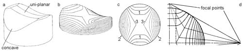
Figure 1. Development of the surface-contours and cut-outlines
The working drawings for this component (kindly supplied by Protek AG, Switzerland) were used to create a threedimensional model of the articulating surface in the AutoCad environment (AutoDesk Inc., Sausalito, CA). The threedimensional modeling routines within AutoCad were then used to sequentially cut slices through the surface (Figure 1b): the slice-outlines, projected onto a single plane, produced a contour map of the surface (Figure 1c). Clearly there are two distinct groups of contours (1 and 2), plus two border-contours (3). Lines were drawn from the ends of, and perpendicular to, the border-contours: due to component symmetry, the intersections of these lines were used to define four focal points (Figure 1d). Cutting lines were drawn from these focal points, such that they joined at the respective border-contour and stopped at the edge of the central area (dotted lines) which would lie over the uni-planar central section of the patella component. Median lines, drawn between the cutting lines, were used as backbones to develop each petal-like segment of the final cut-out. The developed shape for each petal was determined using the contour-width between cutting lines and the median line length (along the three-dimensional surface) between contour lines.
Discussion
The resulting cut-out is shown in Figure 2. Tabs have been added to the ends of the uni-planar section, to allow for ease of location of this complex shape to the patellar surface. This shape allows the film to lie over the complex three-dimensional patellar surface, without crinkling and with a maximised area of coverage.
The cutting of Fuji film into such complex shapes can be a challenge. We discovered that it is possible to print the cut-out shape onto the back (non-active) surface of the film using a flatbed plotter and light application of the pen. Cutting of the film should be conducted using a sharp scalpel (taking into account that the pressure of the cutting edge will activate the chemical-release mechanism, thereby rendering this area inactive for subsequent datacollection).
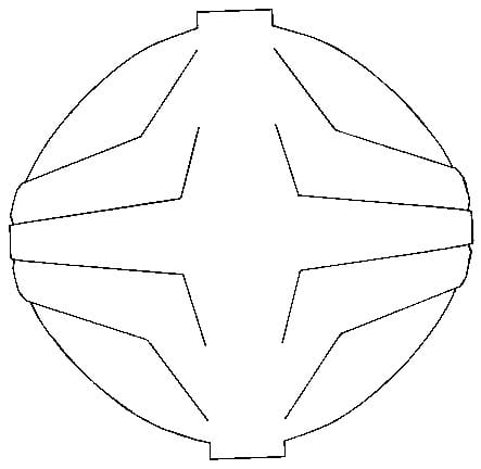
Figure 2. Final Cut Out Shape.
While this technique was developed for the application of Fuji film over a specific surface, components of this method can be easily transferred to other complex surfaces and other transducers (with the exception of the real-time devices which rely on contacts running across the film, which would be sacrificed using this technique).
References
- Fukubayashi, T. and Kurosawa, H. Acta Orthopaedica Scandinavica, 51: 871-879, 1980.
- McNamara, J.L., et al. Clinical Orthopaedics, 299: 104-113, 1994.
- Marder, R.A., et al. Journal of Bone and Joint Surgery, 75A(1): 35-45, 1993.
- Singerman, R.J., et al. Experimental Mechanics, 27(1): 99-105, 1987.
- Harris, M.L., et al. Journal of Biomechanics, 32: 951-958, 1999.
- Liggins, A.B., et al. In: Little, E.G. (Ed), Experimental mechanics: Technology transfer between high tech engineering and biomechanics. Amsterdam: Elsevier Science Publishers. 61-70, 1992.
- Liggins, A.B. In: Shelton, J.C. and Orr, J.F. (Eds), Optical measurement methods in biomechanics. London: Chapman and Hall. 174-189, 1995.
- Caldwell, N.J., et al. Journal of Biomechanics, 26(8): 1001-1009, 1993.
- Afoke, N.Y.P., et al. Journal of Bone and Joint Surgery, 69B(4): 536-541, 1987.
![]()