Lukas Zach, Lukas Horak, Pavel Ruzicka and Svatava Konvickova
Abstract—Common total knee endoprosthesis (TKE) consist of a metal femoral component and a tibial component (an UHMWPE plateau and its metal tray). Though metal in case of the femoral component can be replaced with the more progressive material like Zirconia [1] (the endoprosthesis developed with a contribution of our Laboratory of Biomechanics) a loading remains unchanged. For future development of actual endoprosthesis, a quality FE model seems to be a key-goal. While developing a dynamic model [2] of a lower limb focusing on the knee joint with the implanted endoprosthesis, every partial result is being verified.
One of the most important characteristics of the endoprosthetic system using the UHMWPE plateau is contact pressure between the plateau and the femoral component. For the mechanical test serving for verification of contact pressures (formerly calculated by FEA) by means of pressure sensitive films, special jigs were designed for the femoral and the tibial component and the measurement up to 3000 N were made. Then using the single-purpose software, magnitudes and a distribution of a contact pressure were calculated and compared with FEM results. Since a geometric model of the endoprosthesis and a factory-made endoprosthesis seem not to be identical in shape of contact surfaces, a result comparison was very hard. Based on a position of a contact and its area we beg to conclude that the results are very promising.
Index Terms— contact pressure, finite element analysis, knee joint, pressure sensitive film.
I. INTRODUCTION
A unique ceramic total knee endoprosthesis (TKE) made of Zirconia was developed as a substitution for a Co-Cr-Mo alloy femoral replacement which is standardly implanted as a part of Medin Modular System (a knee joint endoprosthesis by Medin Orthopedics). The Zirconia femoral component would be a unique solution for patients at a risk of an alloy allergic reaction (4-5% of the population) or young and active patients who could have an alternative to the current endoprosthesis [1]. This ceramic femoral component was designed by several groups and laboratories, among them the Laboratory of Biomechanics, Department of Mechanics, CTU in Prague, but the main designers were the companies Walter, Prague (Medin Orthopedics today) and Dias, Turnov (Saint-Gobain today).
A reliability of finite element analyses (FEA) is raised by other tests especially mechanical proving the FEA results. There are not many possibilities how to measure contact pressure which is one of an important output of FEA. We have chosen special films by FUJI [3] designed to register the pressure distribution over any surface [4, 5 and 6]. A limitation of these films is their use only for static tasks.
In order to be able to predict, by means of the FEA, the stress and contact pressure distribution over the total knee replacement (TKR), the comparison of the results helps us to develop our FE models [1, 2]. At the moment, our complex lower limb model consists of 5 bones, 32 muscles and 11 ligament bundles.
II. MATERIALS AND METHODS
As said before, the aim of this paper is to publish the comparison of the results of contact pressures between the Co-Cr-Mo FC and the tibial plateau given by special film (provided by Fuji) and the FEA. In order to do so, we had to prepare the FE model matching the mechanical test. The loading was performed on MTS 885 MiniBionix for the forces of 500-3000 N with 500 N stepping.
A. Finite Element Method
To fulfill a main demand, identity of the FE model and the experiment, we used for the FEA the same TKR and the same design of its jigs. A loading force and boundary conditions agreed with the test also. Only one contact pair (type “hard-contact” was defined in the problem, between the femoral and tibial component with a coefficient of friction of 0.3. All material models instead of a material model of polyethylene were prepared according to a theory of elastic materials. UHMWPE was supposed to behave according to an ideal elasto-plastic model, see fig. 1. For more details about the material constants see table 1.
A tetrahedral mesh of C3D10M elements was created semi-automatically with local refinement on a contact area (see fig. 3).
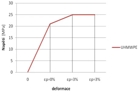
Fig. 1 – Material model of UHMWPE
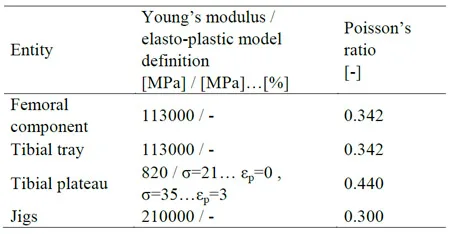
Table 1 – Material properties
B. Pressure Sensitive Films
Using MTS 885 MiniBionix machine during the test, firstly special jigs for TKR was designed and manufactured to be able to translate a loading force of up to 3000 N. The final assembly can be seen in the fig. 2. An original TKE (size 68, right leg design) as well as the geometric model used in FEA was provided by the producer (Medin Orthopedics, Prague). The upper fixation allowed the metal femoral component a madio-lateral rotation while the bottom jig prevented the UHMWPE tibial plateau from any translations and rotations. The Prescale films were applied on the tibial plateau covering all the contact area according to the fig. 2.
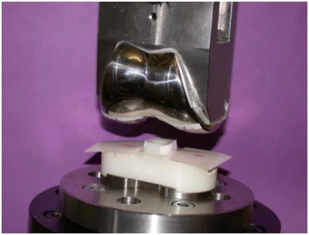
Fig. 2 – Mechanical test
There are several types of pressure sensitive films. A Film by Fuji called “Prescale” has been used during our test. Three kinds of Prescale are distinguished according to expected magnitudes of contact pressures (0.2 – 130 MPa). Types LW and MS covered the range of the contact pressures which we aimed to monitor.
Since we lacked an original evaluating machine and software, to evaluate the red-coloured map after an impact of the femoral component against the tibial plateau, calibration and verification tests preceded. As the evaluation tool for the red-colored scans of the films, a general-purpose computing, data analysis and visualization environment Matlab (MathWorks, Natick, MA, USA) has been chosen. Necessity of a special-purpose program is evident. This software was able to transform the red-colored maps into the FE-looks-like maps. The output of it was the following quantities: maximal contact pressure, mean contact pressure and contact area.
For red-colored imprints digitalization a high-resolution scanner has been used. Firstly, simple impact tests (plane surface-plane surface and plane surface-cylindrical surface) had been made and evaluated to calibrate the evaluating software to fit the theoretical results, and then the mechanical test with the TKE followed.
III. RESULTS
Based on the aim of this work, the results of contact pressures a
nd contact areas are presented for following values of loading: 500 N, 1000 N, 1500 N, 2000 N and 3000 N. A typical shape and locations of the imprint on the Prescale film can be seen in the fig. 3. As additional comparative data, contact areas calculated by FEA and measured by Prescale films follow (table 2). Only the sum of the medial and the lateral contact area is compared.
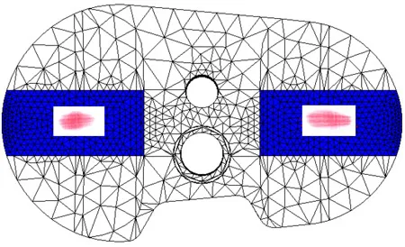
Fig. 3 – Impact shape and location
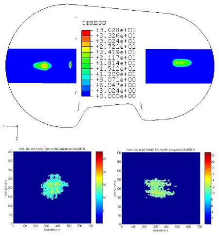
Fig. 4 – Comparison of contact pressure results: F=500 N
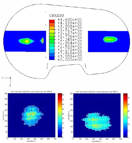
Fig. 5 – Comparison of contact pressure results: F=1000 N
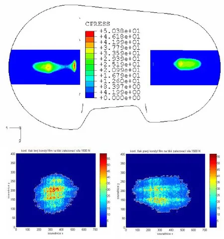
Fig. 6 – Comparison of contact pressure results: F=1500 N
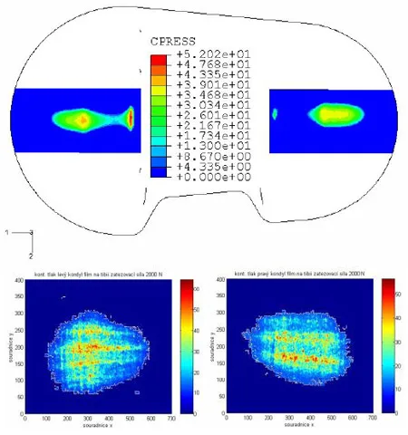
Fig. 7 – Comparison of contact pressure results: F=2000 N
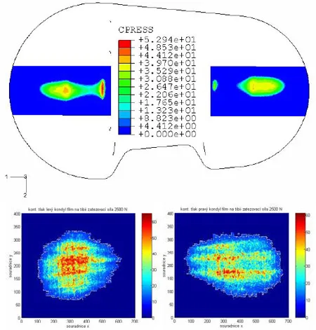
Fig. 8 – Comparison of contact pressure results: F=2500 N
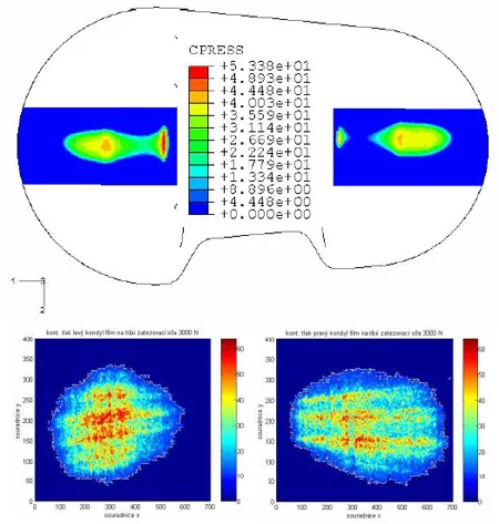
Fig. 9 – Comparison of contact pressure results: F=3000 N
![Table 2 – Contact Area (comparison) [mm2] table 2](https://www.sensorprod.com/wp-content/uploads/2023/08/table-2-9.jpg.webp)
Table 2 – Contact Area (comparison) [mm2]
IV. CONCLUSIONS
A key to a successful FE model, able to predict stress fields, contact pressures, contact areas etc., is its permanent validation. Accordance of both approaches, the final element analysis and the mechanical tests, can stand at the beginning of further, more complex, FE models.
Laboratory of Biomacheanics, CTU in Prague participates at a development of various types of biomechanical devices, among others a zirconia femoral component of a Medin Modular total knee endoprosthesis (TKE). As a verification tool of our FE model of a lower limb focused on a knee joint, pressure sensitive films have been used. We designed special jigs for a fixation of the total knee endoprosthesis featuring the Co-Cr-Mo femoral component, the UHMWPE tibial plateau and its metal tray. Using special pressure sensitive films “Prescale” by Fuji [3] (types LW and MS) loads up to 3 kN were applied on a MTS 885 MiniBionix machine. Red-colored films were then scanned and using a special-purpose program in Matlab, these maps were transformed to a color scale corresponding to contact pressure as known from FE codes. Due to lack of an original evaluating machine and software provided by Fuji to exactly evaluate the color map after the loading, a calibration and verification tests of developed software preceded.
The results of contact pressures and contact areas showed encouraging accordance. Firstly, though contact area was always a larger in case of a FEA (ranging from 2.5 times higher for F=500 N to 1.21 times higher for F=3000 N), a contact position was almost identical. On FEA results, there are in fact two contact areas on each condyle which can be distinguished. “A bearing contact area” and a “medio-lateral stabilization contact area” (see fig. 10). The “stabilization area” is a specially formed shape of the tibial plateu which limits a medio-lateral shift of the femoral component. The differences in contact area could be given by different shape of the geometrical model and the real knee on one side and a coarse mesh on the other side.
Secondly, based on different contact areas, peak values of contact pressures are hardly comparable. It can be supposed that disposing the identical geometric model and the edoprosthesis, the results would be more corresponding.
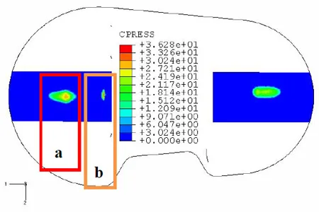
Fig. 10 – Contact areas calculated by FEA:
a) “bearing contact area”
b) “medio-lateral stabilization contact area”
Though a geometric model of a Medin Modular total knee joint edoprosthesis should serve as an ideal shape of the TKE, a comparison of contact pressures and contact areas showed discrepancies between the model and the real endoprosthesis leading to the results disagreements. Due to the above mentioned reasons, we beg to make a conclusion that our FE models are well designed and improving of a material model of UHMWPE and another local refinement of the current meshes which directly influence a shape contact surfaces could improve our FE analysis.
REFERENCES
- Zach, L., Konvickova, S., Ruzicka, P., Development of a finite element knee model after total replacement operation. In Proceedings of the 4th Youth Symposium on Experimental Solid Mechanics, Castrocaro Terme 4-7 May 2005, University of Bologna, Bologna, Italy, 2005, pp. 75-76, ISBN 88-901080-2-9-44406.
- L. Zach, S. Konvickova, P. Ruzicka, “Finite element analyses and other tests of ceramic knee joint replacement (WDM system),” in Proceedings of IFMBE, Prague 20-25 November 2005. Prague, Czech Republic, vol. 11, 2005, ISSN 1727-1983.
- FUJI Prescale Pressure Sensitive Film [Online]. Available: https://www.spareonweb.com/fr_red.htm
- M.L. Harris, P. Morberg, W.J.M. Bruce, W.R. Walsh, “An improved method for measuring tibiofemoral contact areas in total knee arthroplasty (a comparison of Kscan sensor and Fuji film),” in J. Biomechanics, vol. 32, issue 9, 1999, pp. 951 – 958.
- Jiann-Jong Liau, Cheng-Kung Cheng, Chun-Hsiung Huang, Wai-Hee Lo, “Effect of Fuji pressure sensitive film on actual contact characteristic of artificial tibiofemoral joint,” in. Clinical Biomech., vol. 17, 2002, pp. 698-704.
- Jiann-Jong Liau, Chi-Chung Hu, Cheng-Kung Cheng, Chun-Hsiung Huang, Wai-Hee Lo, “The influence of inserting a Fuji pressure sensitive between tibiofemoral joint of knee prosthesis on actual contact characteristics,” in Clinical Biomech., vol. 16, 2001, pp. 160-166.
Manuscript received March 6, 2008. This work was supported in part by the Ministry of Education of the Czech Republic under Grant MSM 6840770012. L. Zach is with Laboratory of Biomechanics, Czech Technical University in Prague, Faculty of Mechanical Engineering, Technická 4, 166 07 Praha 6, Czech Republic (phone: +420-224-325-542; fax: +420-233-322-482; e-mail: Lukas.Zach@fs.cvut.cz). L. Horak, was with Laboratory of Biomechanics, Czech Technical University in Prague, Faculty of Mechanical Engineering, Technická 4, 16607 Praha 6, Czech Republic. P. Ruzcka is with Laboratory of Biomechanics, Czech Technical University in Prague, Faculty of Mechanical Engineering, Technická 4, 16607 Praha 6, Czech Republic (e-mail: Pavel.Ruzicka@fs.cvut.cz). S. Konvickova is with Laboratory of Biomechanics, Czech Technical University in Prague, Faculty of Mechanical Engineering, Technická 4, 16607 Praha 6, Czech Republic (e-mail: Svatava.Konvickova@fs.cvut.cz).


