

Article
Related Links
Christopher L. Golden
George W. Woodruff School of Mechanical Engineering Georgia Institute of Technology May 2008
Approved by: Professor Shreyes N. Melkote, Chair, School of Mechanical Engineering Georgia Institute of Technology
Professor Steven Y. Liang School of Mechanical Engineering Georgia Institute of Technology
Professor Suresh K. Sitaraman School of Mechanical Engineering Georgia Institute of Technology
Summary
Slender ring-shaped parts, such as mechanical seals and bearing races, ex- perience elastic deformation due to workholding and cutting loads applied during turning. Workholding loads contribute to workpiece positional errors prior to turn- ing, and machining loads contribute to machined form errors. These form errors often require finishing operations, such as grinding or lapping, to ensure that the workpiece geometry meets prescribed dimensional tolerances. Finishing operations can be time consuming and environmentally unfriendly, and their removal from the manufactur- ing process can significantly reduce both production time and cost. Consequently, it is desirable to understand and predict the contribution of workholding and machin- ing loads to elastic deformation during turning in order to minimize form errors and maximize final part quality.
This thesis presents a method for the prediction of final out-of-plane surface profile variation in face turning of rings of non-uniform cross section. A ring of non-uniform cross section is one that has a radial cross section of non-uniform thickness over the height of the ring. An analytical model was developed to predict the final peak-to- valley (PTV) surface profile variation of the face of a machined ring. The model is a superposition of several key factors that affect the final surface profile variation. These factors include initial surface profile variation, elastic deformation due to workholding, material removal during machining, workpiece de ection due to cutting forces, and elastic recovery due to unclamping. Furthermore, finite element analysis was carried out to relax some of the assumptions made in the development of the analytical model to provide a more accurate prediction of the final PTV surface profile variation.
A series of experiments was performed to validate both the analytical and finite element models. The first series of experiments examined the PTV surface profile variations of a set of cobalt alloy (Stellite) rings throughout a facing operation. The second series of experiments characterized the clamping force produced by a three- jaw chuck. The third series of experiments measured the cutting forces applied to the workpiece during the facing operation. Analytical and finite element results cor- respond well with experimental observations, with average relative errors of 11.6 and 7.2 percent, respectively.
Introduction
1.1 Machining Processes
Many products manufactured using casting, forming, and shaping require additional processing to impart specific geometric characteristics to the workpiece. These processes are called material-removal processes [3]. Machining is the general term used to describe material-removal processes, and it can be divided into three major cat- egories: cutting, abrasive processes, and advanced machining processes. Cutting is of primary importance to this research, and it is the focus of the remainder of this section.
Cutting typically involves single-point or multi-point cutting tools in processes such as turning, boring, drilling, and milling. The milling operation shown in Fig- ure 1.1 is representative of a cutting process. Cutting and other material-removal processes are often more desirable than other manufacturing processes for various reasons:
- Greater dimensional accuracy than casting, forming, etc.
- External and internal geometric features that cannot be produced by other processes
- Finishing operations can be applied after material treatment
- Special surface characteristics and textures can be applied
- Often more economical than other processes, especially for small batch sizes
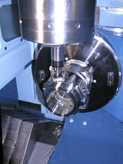
Figure 1.1: Milling machine and workpiece [1]
However, cutting and other material-removal processes also possess several unfavorable qualities:
- Raw material wasted in the form of chips
- Generally longer process time
- Possible adverse effects on part surface integrity
Despite these unfavorable aspects, material-removal processes play a significant role in modern manufacturing technology.
Many cutting processes produce parts which are basically round in shape. These processes produce small and large parts alike, and are typically accomplished by turning a workpiece on a lathe. A lathe, like the one shown in Figure 1.2, is a cutting machine that has a rotating spindle. Cutting is accomplished by fixing the workpiece in a workholding device and rotating the spindle-workpiece assembly. While the part rotates, a cutting tool moves axially and radially about the part to achieve the desired part geometry. The starting material in turning is usually a workpiece that has been made by another manufacturing process such as casting or forging.
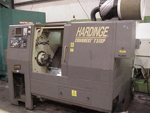
Figure 1.2: CNC lathe [2]
Turning processes are versatile and can produce a variety of shapes and effects. The various types of turning processes, shown in Figure 1.3, include:
- Turning straight, conical, curved, and grooved workpieces
- Facing to produce a flat surface at the end of the part
- Producing various shapes by form tools
- Boring to enlarge a hole or produce internal grooves
- Parting to cut a piece from the end of a part
- Threading to produce external or internal threads
- Knurling to produce a shaped geometric roughness on cylindrical surfaces
Several important parameters should be considered when designing a turning (or other material-removal) process. Some of these factors are:
- Tool geometry
- Feed
- Rotational speed
- Depth of cut
- Clamping loads
- Cutting loads
Standard machine cutting tool inserts are produced and sold in an array of shapes and sizes, as shown in Figure 1.4. Insert geometry may vary in shape, thickness, rake angle, relief angle, nose radius, etc. Each of these insert features has an effect on cutting characteristics such as chip flow direction, cutting tool tip strength, cutting force magnitude, and surface finish. Additionally, feed,
rotational speed, and depth of cut each have a profound effect on material-removal processes in areas including tool wear, workpiece temperature, cutting force magnitude, and tool-workpiece deflection. Finally, clamping and cutting loads also play an important role in turning operations. Clamping loads tend to distort a workpiece as it is being fixed to the lathe spindle. Cutting loads tend to deflect a tool or workpiece during cutting. Each of these mechanisms contributes to workpiece form errors in a material-removal process.
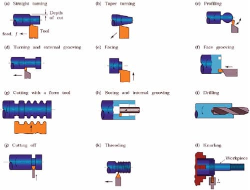
Figure 1.3: Various turning processes [3]
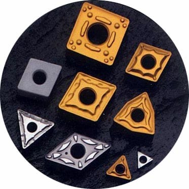
Figure 1.4: Variety of machine tool cutting inserts [4]
1.2 Workholding
Workholding entails fixing a workpiece to a machine tool in preparation for a material- removal process. Workholding devices called clamps are used to fix a workpiece to a machine table or lathe spindle [5]. An overview of the various types of clamps and their operating principles is shown in Figure 1.5. Because of the wide variety of workpieces considered across all material-removal processes, force closure is the most common clamping technique. The force can be applied electrically, hydraulically, or pneumatically. Some common types of force closure clamps are the machine vise, clamping chucks, and collet chucks. Other physical operation principles can also be used to clamp a workpiece. A magnetic force can be applied by a permanent magnet or electromagnet, or an adhesion force can be applied as a result of a vacuum between the clamp and the workpiece.
Mechanical workholding devices provide adequate clamping loads for high fixture stiffness, but they do cause some amount of local elastic/plastic deformation of the clamped workpiece. In comparison, magnetic and vacuum clamps do not induce significant local workpiece deformation, but they often cannot apply appropriate clamping loads for workpiece processing. Consequently, much research has been completed to develop other workholding methods. Some current research focuses on the use of electrorheological fluids for clamping. Electrorheological fluids increase in viscosity when subjected to an electric field. This phenomenon is caused by a clustering of electrorheological particles in the fluid parallel to the electric field [5]. Electrorheological fluids can conform to the shape of any workpiece and may eventually be used in a fully flexible fixturing device.
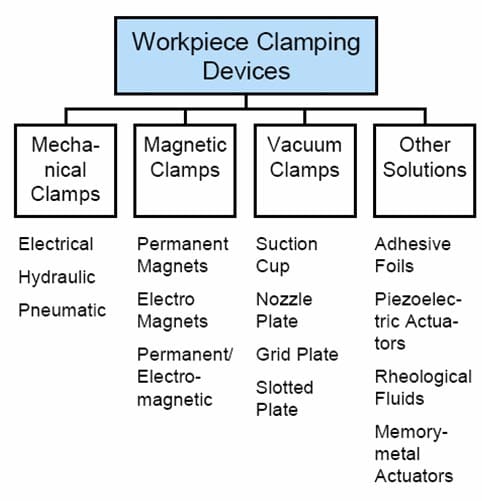
Figure 1.5: Clamping devices [5]
1.3 Form Errors
Other unique fixturing approaches have also been explored. A light activated gripper technology uses a photosensitive structural adhesive to adhere workpieces to fixtures [5]. A multi-pin support method has also been developed. Pins are allowed to move and mimic the negative shape of the clamping surface. When the workpiece makes appropriate contact with the multi-pin device, all pins are fixed and the support becomes rigid [5].
A workpiece typically has a desired, or nominal, form and a set of allowed variations, or tolerances, from that nominal form. The nominal form dimensions and allowed tol- erances are controlled by geometric dimensioning and tolerancing (GD&T) standards seen on industrial drawings. There are several different types of form dimensions defined by GD&T standards such as circularity, cylindricity, atness, and straightness. Circularity is a measure of the roundness of an individual cross section of a feature, and cylindricity is a measure of the roundness of a cylinder for all of its cross sections simultaneously. Flatness is a measure of a feature deviation from a defined planar surface, and straightness is a measure of feature deviation from a defined straight line. If a finished part dimension lies outside of its defined tolerances, it is known as a form error. More strictly, a feature exhibits a form error if it varies in any way from its nominal dimension
There are many sources of machining errors in manufacturing applications. Form errors can be categorized into individual { those that affect only one feature { and combined { those that propagate through the entire machined component [9]. Individual feature errors can be grouped into three subcategories: i) cutting tool errors, ii) programming errors, and iii) miscellaneous errors. Cutting tool errors include tool size error, misalignment error, tool wear, and tool deflection. Programming errors in- clude feature size error, feature position error, and interpolation error. Miscellaneous individual feature errors include errors relating to cutting conditions such as chatter and workpiece deflections. Combined feature errors can also be divided into three subcategories: i) machine tool errors, ii) fixturing and workholding errors, and iii) miscellaneous errors. Machine tool errors include machine calibration error, servo lag and interpolation error, stiffness error, and thermal distortion error. Fixturing and workholding errors include set-up error at the part-fixture, machine-fixture, and part- machine interfaces and insuffcient chip control. Miscellaneous errors include items such as dimensional error of the stock material. Each of these types of individual and combined feature errors can emerge as a form error in the final workpiece state.
In cylindrical turning, the most common form errors occur with regard to the circularity and cylindricity of the workpiece. Any exibility in the machine system in the direction of the radial cutting force yields a relative displacement at the tool- workpiece interface where the finished surface is generated [10]. Because the workpiece (or tool) is pushed away in the radial direction, the final machined cylinder will have a surplus of stock, or form error, at the location of the deflection. Similar form errors can be introduced in a turning process by the fixture clamping loads. A ring-shaped workpiece, shown in Figure 1.6a, will deform elastically when held in a mechanical chuck (Figure 1.6b). The inner diameter of the workpiece is then cut to a nearly true circular profile (Figure 1.6c). The workpiece tends to return to its original shape when released from the chuck and permanent circularity form error is introduced to the finished workpiece (Figure 1.6d). It is noted that the ring shown in Figure 1.6 is not representative of the non-uniform cross section rings examined in this research. However, it is a representative example of a way in which form error can be introduced to a ring-shaped workpiece.
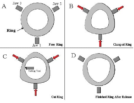
Figure 1.6: Introduction of circularity error by workholding device [6]
1.4 Research Goal and Objectives
In view of this information, it is desirable to understand and predict form errors and elastic deformation behavior in order to minimize form errors and maximize part quality in a non-uniform cross section ring machining operation. This thesis presents a method to analyze the form errors produced in face turning of ring-shaped parts of non-uniform cross section (e.g. mechanical seals) held in a three-jaw chuck. Therefore, the primary objectives of this thesis are:
- Development of an analytical model to predict the effects of workholding and machining loads on the final out-of-plane peak-to-valley (PTV) surface profile variation of the face of a thin ring of non-uniform cross section
- Development of a finite element model to predict the effects of workholding and machining loads on final out-of-plane PTV surface profile variation of the face of a thin
ring of non-uniform cross section - Experimental characterization and validation of the effect of workholding and machining loads on final out-of-plane PTV surface profile variation of the face of a thin ring of non-uniform cross section
These goals have been accomplished by the analytical modeling and experimental verification efforts described in subsequent chapters of the thesis.
1.5 Research Approach and Thesis Outline
This research focuses on the analysis of form errors in rings of non-uniform cross section due to workholding and machining loads. For the purposes of this thesis, a ring of non-uniform cross section is one that has a non-uniformly shaped radial cross section. The thesis approach involves exploring factors affecting the out-of-plane PTV surface profile variation of cobalt alloy (Stellite) rings. The PTV surface profile variation of a ring is measured at each stage of the manufacturing process to track the contributions of the various steps to the total PTV surface profile variation. This tracking will allow for a methodical isolation and analysis of the individual factors that contribute to form errors.
While significant work on form errors produced by turning thin or slender rings has been reported, it focuses primarily on form errors induced by radial deformation. There has been little or no work reported on form errors induced by axial or out- of-plane deformation. Axial workpiece deformation can be the result of workholding or machining loads like those applied in face turning. Workpiece deformation during the machining process causes both geometric position errors and workpiece deflection errors. The geometric position and workpiece deflection errors account for nearly all of the final workpiece form error. Therefore, considerable effort is needed to minimize both of these sources of error to improve part quality.
Chapter 3 addresses the development of an analytical model to predict the final PTV surface profile variation of the ring face as a function of the initial part form error, and workholding and cutting force induced elastic deformations. It also focuses on the development of a finite element model built to validate and increase the accuracy of results obtained with the analytical model. Chapter 4 details experiments that were conducted to characterize clamping and cutting forces and workholding-induced elastic deformation before and after face turning of Stellite rings. Experimental results are also compared with those obtained from the analytical and finite element methods in Chapter 3. Chapter 5 presents the conclusions of the thesis and proposes future research work in this area. Fig. 1.7 demonstrates the overall research plan with each block representing an individual research activity.
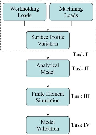
Figure 1.7: Research plan for study of workholding and cutting loads on thin rings
Literature Review
Form errors are ubiquitous in material removal processes and are well documented in the literature. Characterization and prediction of form error has been researched thoroughly for many workholding schemes and machining processes. Form error analysis and prediction have been studied extensively in face milling [11, 12, 13] and turn- ing [12, 14, 15, 16]. However, investigation of form error in machining of metallic ring-shaped parts with non-uniform cross sections such as mechanical seals has been largely unaddressed. This operation presents significant challenges that inhibit the achievement of an acceptable surface profile.
This chapter presents a review of prior relevant research that explores several factors that contribute to form error of finished workpieces. The literature review is divided into four sections. First, an overview of the effect of initial part form on form error is presented. Next, the impact of various workholding strategies on form error is addressed. Third, the effect of machining processes on form error is considered. Finally, several methodologies for modeling form error are reviewed.
2.1 Form Error and Initial Profile Variation
Vajpayee [17] investigated form error in turning of cylindrical workpieces. He found that final form error was independent of the magnitude of the initial form error. In his research the experimental depth of cut was 1 mm, and the initial induced form error was within the range of ±0.2 mm.
The remaining body of literature is limited in its discussion on the effects of initial form on the achievement of ideal form in other machining processes. This thesis conjectures that initial form error of unfinished workpieces (especially flatness error) can impact the geometric position of a surface that is to be machined. This type of geometric error can alter the theoretical depth of cut and can yield a finished workpiece that is poorly dimensioned and potentially out of tolerance.
2.2 Form Error and Workholding
The contribution of workholding deformation to final form error is evident, and significant research has been performed in this area. Workholding systems contribute to machining errors in two ways [18]. The first contribution involves the effects of the fixture on workpiece or process dependent characteristics such as workpiece stiffness, clamping force, depth of cut, etc. The second contribution is by the general design of the fixture, including factors such as locator and clamp geometry and placement, the clamping sequence, etc. As such, the workholding device contributes to the overall machining system error and may either positively or negatively impact its accuracy.
In either scenario, fixturing induces elastic deformation in the region of the workpiece- fixture contact, and the deformation can have a significant effect on the geometric accuracy of the workpiece and its overall machined surface [19]. Consequently, optimum fixture layout is needed to obtain desired form, geometric integrity, and surface finish.
Several researchers have explored the circularity error that is the result of a deformed workpiece held in a three-jaw chuck. Morimoto et al. [20] described a method to compensate for the circularity error by tracing the deformed profile of the work-piece with a numerical control lathe and amending the cutting program to obtain the ideal part geometry in its final unclamped state. Consequently, the circularity error of the studied workpieces was reduced by as much as 80 percent. While this method of error reduction is successful, the tracing process requires additional workpiece process time and would not be desirable in a high volume industrial setting.
Rahman and Ito [21] investigated the machining accuracy of solid cylindrical work- pieces held by a three-jaw chuck. They attributed circularity and cylindricity form error mainly to radial stiffness variations in the chucked workpiece that resulted from the position of the chuck jaws relative to the radial cutting force. However, because all workpieces exhibit some amount of stiffness variation, the resulting machining in- accuracies are also influenced greatly by radial cutting forces and chucking conditions.
Walter and Stahl [22] examined workholding de ection and clamping forces in turning of ring-shaped workpieces. They developed two models to predict the min- imum clamping force needed to turn a ring-shaped workpiece. The first model considered workpiece stiffness to be greater than that of the chuck jaws, and the second model considered workpiece stiffness to be less than that of the chuck jaws. Results from these analytical models were compared quite favorably to finite element analysis, but no experimental results were presented for their validation.
Malluck and Melkote [23] explored the deformation of ring-shaped workp
ieces due to in-plane chucking forces. The effect of chucking forces on part circularity when machining compliant workpieces was emphasized. A theoretical model was developed to predict the deformation behavior, and it can be used to optimize the fixture design for machining of ring-shaped workpieces. Kurnadi et al. [24] extended this research to include the effects of additional fixture characteristics, such as the number of chuck jaws, on the circularity of thin ring-shaped parts turned in a lathe. A workholding optimization model was developed to determine the minimum number of chuck jaws and the range of acceptable chucking forces needed to obtain the desired workpiece circularity and prevent workpiece slip during machining. These works clearly present the effect that radial deformation due to workholding loads can have on final part form error.
The majority of form errors that occur during workholding of uniform cross section rings can be assumed to be due to in-plane chucking and cutting forces [22, 23]. Thus, the distortion caused by mechanical chucking is almost entirely radial in nature. Consequently, the uniform application of chucking forces in these studies did not require consideration of out-of-plane form error effects. Similar distortion occurs during chucking of non-uniform cross section rings, but it is both radial and axial in nature due to the application of out-of-plane chucking forces. This distortion leads to a more complex interaction between initial part form, workholding, and machining variables.
Significant work has also been focused on the improvement of fixture designs to reduce workholding deformation. Nee et al. [25] developed a method of dynamic chuck control in milling. In this control methodology the fixturing system employed dynamic clamping with sensory feedback and the ability to apply a precise clamping intensity. It was shown to reduce workpiece distortion and improve workpiece quality. Kurnadi et al. [24] also proposed a method of dynamic chuck control in turning to minimize workpiece circularity errors that are obtained in conventional constant force chucking.
2.3 Form Error and Machining Processes
The effect of machining parameters on form error is also well documented. In addition to the error induced by workholding loads, challenges in obtaining an acceptable part profile also stem from the application of cutting forces normal to the machined surface that cause workpiece and/or cutting tool deflection. Form error due to cutting loads is one of the primary error sources in metal cutting processes because of the large magnitude of required cutting loads [18]. This is especially important when machining flexible parts in which workpiece deflection during machining is the main cause of form error [26]. Budak [16] also states that cutting force is the most fundamental and significant parameter in machining operations, potentially causing part and tool deflections and tolerance violations.
Cutting forces result in a change in position of the workpiece with respect to the cutting tool or vice versa [23]. Thus a rigid workpiece yields greater form accuracy than a compliant one, and a light depth of cut tends to yield greater accuracy than a heavy one for a given metal cutting machine. Some studies have neglected the effects of cutting force errors due to the small magnitude of cutting loads in finish machining. However, many industrial operations require machining of hard workpieces to their final form without any finishing operations. Such operations involve large cutting forces, and their corresponding cutting force errors cannot be ignored.
Several authors have reported on form error in cylindrical or ring-shaped parts due to cutting forces. Kops et al. [11] explored the effect of cutting forces on workpiece deflections of turned cylinders. The emerging (or final) diameter was used to predict workpiece deflections to account for the increasing compliance of the workpiece during machining. The effect of increased workpiece compliance on maximum part deflection was shown to be pronounced for increasing depths of cut and increasing workpiece slenderness. Thus, use of the emerging diameter allowed for more accurate prediction of maximum workpiece deflection due to cutting forces.
Kovvur et al. [13] also explored form error in turning of cylindrical parts. Feed, spindle axis error, and tool nose radius were found to have significant impacts on finished part form error. Form error was uninfluenced by cutting speed. These results were used to develop a general model for the prediction of cylindrical part surfaces machined by single-point cutting.
Nowag et al. [27] investigated the effects of machining parameters in turning on the distortion of bearing rings. Feed (0.1 { 0.4 mm) was found to have a slight influence on the distortion of the bearing rings, but cutting speed (200 { 300 m/min) and depth of cut (0.5 { 1.5 mm) were not.
Many efforts have been made to minimize cutting force errors prior to or during machining. Eman [28] introduced an active form error compensation strategy. This strategy used error motion signals to forecast the future tool-workpiece displacement and apply the appropriate compensatory action. Walter and Stahl [22] developed a model to determine the maximum allowable cutting forces, and used the maximum cutting forces to obtain optimum cutting parameters prior to cutting. Sasahara and Tsutsumi [29] developed a method to optimize cutting parameters using a tool status database. A variable feed rate method that adjusts feed rate in different part locations to minimize cutting force errors in critical locations has also been proposed [16]. The variable feed rate method allows for reduction of cutting force errors in large deflection locations and increased productivity in smaller deflection locations.
2.4 Modeling of Form Error
Another focus of the literature relates to modeling and prediction of form error. Predictive models have been developed that use both analytical and computer-based methods. Analytical models tend to achieve a predictive solution with greater speed and simplicity, while computer-based models tend to achieve a predictive solution with greater accuracy.
Ozturk and Budak [30] explored tool de ections and workpiece form errors in five-axis ball-end milling. They applied predicted cutting forces to tool and work- piece structural models to determine deflections. The workpiece considered was a rigid block, and their model used only cutting tool deflections to predict form error. While this model yielded reasonably accurate results, a robust predictive model for compliant workpieces must include both tool-workpiece and workholding effects.
Kline et al. [31] also investigated form error in end milling. They combined a previously developed cutting force system model with a cutting tool deflection and workpiece deflection model to predict overall surface error. The model considered the contribution of machining conditions, workpiece geometry, and material properties of both the end mill cutter and the workpiece. Both the trends and the magnitudes of the model results were compared favorably with experimental data from milling of aluminum workpieces.
Wan et al. [32] used finite element method to predict static form errors in peripheral milling of thin-walled workpieces. They investigated issues such as finite element discretization of cutting forces, tool-workpiece coupling, and variation in workpiece rigidity due to its complex geometry. Irregular finite element meshes were employed to make improvements in modeling of material removal and iterative tool-workpiece deflections.
Subramani et al. [33] developed a model to compute the cylindricity of machined cylinder bores. The bore cylindricity model accounts for various cutting process parameters and the bore design, and it attributes surface error to both elastic
deflection of the bore due to cutting forces and thermal expansion during machining. Experi- mental data was presented to demonstrate agreement between the analytical model and the physical process.
Mou [34] developed a computer-aided error model to improve the accuracy and effectiveness of a turning process. Rigid body kinematics was used to determine the resultant errors of the machine tool as they relate to the misalignments of the machine tool positioning devices and the workpiece. The error model was further improved by using a computer algorithm to select workpiece measurement points that were least susceptible to measurement errors. The error model was applied and successfully demonstrated in simulations. Yao et al. [35] modeled machining errors in turning via a virtual manufacturing cell. They considered the effects of machining system errors, cutting parameters, and cutting tool edge contour on the machined surface geometry. Predictions were used to create a machined surface topography map.
Masset and Debongnie [26] developed a robust finite element method for node-by- node determination of workpiece deflections. This method applies a single resultant force to a single node and solves the corresponding finite element stiffness matrix.
This step is repeated for each node on the entire machined surface. This method is accurate, but it requires a great amount of solution time. Great strides have been made in the area of solver algorithms to reduce solution time, but an analytical model is required for a more efficient analysis of the contribution workpiece deflections to form errors.
2.5 Summary
This chapter presented a review of prior research relevant to form error in workholding and machining. The literature review summarized each of four areas: i) an overview of the effect of initial part form on final form error, ii) the impact of various workholding strategies on form error, iii) the effects of machining processes on form error, and iv) methodologies for modeling form error. While each of these summaries provided some useful knowledge regarding form error of workpieces subjected to various workholding and machining processes, the current literature is lacking in its discussion of these effects on form error in rings of non-uniform cross section.
Specifically, this work is motivated by the lack of research in the area of form error due to out-of-plane workholding and machining loads. Recorded analyses of workholding and machining of rings have considered in-plane radial forces only, neglecting relatively small out-of-plane forces. However, out-of-plane radial and axial loads become significant in workholding and facing of thin, non-uniform cross section rings. Furthermore, current research does not fully capture the complex interaction between the several factors (initial form, workholding and machining loads, and elastic recovery) that contribute to form error in turning. Consequently, this thesis seeks to address these areas in the analysis and prediction of final peak-to-valley form variation in rings of non-uniform cross section due to workholding and machining loads.
Model Development
An analytical and a finite element model were developed to derive a method for determining the final peak-to-valley (PTV) surface profile variation of the face of a thin ring of non-uniform cross section due to workholding and machining loads. The final PTV surface profile variation is calculated by comparing the maximum and minimum axial coordinates of the final workpiece surface profile. This profile is determined by a general model that consists of four parts: i) elastic deformation due to workholding, ii) material removal, iii) workpiece deflection due to cutting forces, and iv) elastic recovery due to unclamping. An analytical model was developed to solve for each of these components using first principles. Similarly, a finite element model was developed to determine the components of the general surface profile model. The final PTV surface profile variations from the analytical and finite element models can be compared with those obtained experimentally.
3.1 Analytical Model
Consider a thin ring with a non-uniform radial cross section, such as the mechanical seal shown in Figure 3.1. An analytical model was developed to predict the final surface profile of the axial ring face during face turning. The ring is chucked internally with clamping forces applied outward in the radial direction and cutting forces applied in the direction perpendicular to the axial ring face as shown in Figure 3.2.
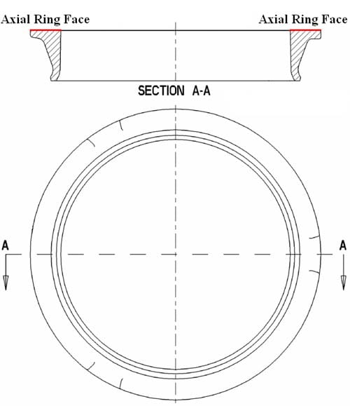
Figure 3.1: Thin ring with non-uniform radial cross section
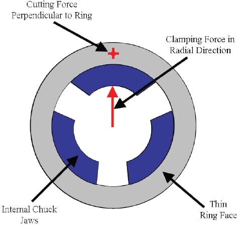
Figure 3.2: Axial view of thin ring shown with internal chuck jaws and cutting force direction
The general surface profile model is a superposition of several key factors that impact the final surface profile. These factors include:
- initial surface profile variation,
- elastic deformation due to workholding,
- material removal during machining,
- workpiece deflection due to cutting forces,
- elastic recovery due to unclamping.
The general model is summarized in Equation 3.1,

where htot and hinit are the final and initial axial surface profile coordinates, δwh isthe axial elastic deflection of the ring face due to workholding, δmach is the thickness of material removed from the ring face during face turning, δwp is the axial elastic deflection of the ring face due to cutting forces, and δrec is the axial elastic deflection of the ring face due to elastic recovery. The following assumptions were made in the development of the general analytical model:
- The ring is considered to be thin, i.e. its mean radius is much larger than its cross-sectional dimensions.
- The ring material is linearly elastic, and the chuck jaw material is rigid.
- Strain hardening and residual stress effects in the ring are neglected.
- Cutting forces in the axial direction are constant and do not vary with depth of cut.
- Applied loads are point loads.
- Ring stiffness does not vary with respect to angular position.
- Local contact deformations due to workholding and cutting loads acting on the ring are neglected.
- The ring does not slide axially or circumferentially with respect to the chuck jaws.
The determination of each of the components that comprise the general surface profile model is described in detail in the following subsections.
3.1.1 Elastic Deformation due to Workholding
An analytical model for elastic deformation due to workholding forces was developed using toroidal deformation theory developed by Biezeno and Grammel [7]. Toroidal deformation or “inversion” of a ring, as shown in Figure 3.3, occurs when a moment, W, is applied to a cross section such that the cross section tends to rotate in its radial plane. When a toroidal moment is applied, the cross section F rotates about a stationary point, O, at a distance R from the center of the ring. The ring rotates through the toroidal angle, ψ, into a new position, F’, and there is assumed to be no shape change for each plane cross section F. Note that F and F’ in Figure 3.3 represent generic non-uniform cross sections. The specific ring cross section examined in this thesis is shown in Figure 3.1 and discussed later in Section 3.2 of the thesis.
The applied moments, W0, are equal in magnitude and are applied in certain axial planes at equal angular intervals around the ring as shown in Figure 3.4. The angular intervals are quantified in Equation 3.2, where n is an integer greater than or equal to 2. This method of moment application is a reasonable approximation for three identical and evenly spaced chuck jaws.

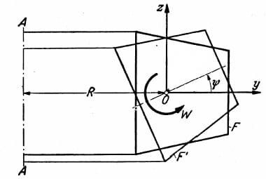
Figure 3.3: Rotation of a ring cross section during toroidal deformation [7]
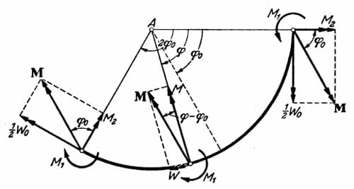
Figure 3.4: Thin ring segment for analysis of toroidal deformation (plan view) [7]
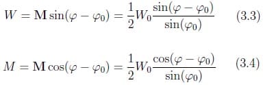
Let one of the applied moments act in the axial plane defined by the angular position φ = 0. In order to characterize the toroidal angle of each ring cross section, an angular section of the ring between neighboring moments must be examined, e.g. between φ = 0 and φ = 2φ0. A toroidal moment of magnitude 1/2W0 is applied at each end of the section, as shown in Figure 3.4. Accordingly, each end of the ring section exerts bending moment components M1 and M2 with vectors parallel to the axis of the ring and normal to the axis of the ring, respectively. The vector M that results from 1/2W0 and M2 is transferred from the end φ = 2φ0 of the ring section to an arbitrary cross section φ such that the transferred vector provides the internal moment at the cross section φ. As such, the components of M form the torsional moment and bending moment given in Equations 3.3 and 3.4, respectively.
The ring is considered to be thin because its diameter is large in comparison to the dimensions of its cross section. Consequently, the stationary point O (see Figure 3.3) is assumed to be the centroid of the cross section F.
In addition to the existing coordinate system (y, z), a new Cartesian coordinate system (η, ζ) is introduced at the cross section centroid, O, such that η and ζ corre- spond to the principal axes of inertia of the cross section F, as shown in Figure 3.5. Prior to deformation, the principal axes are distinct from the y- and z-axes and are separated by an angle λ. The center line formed by the connection of the centroids of the ring cross sections is distorted into a curve by the toroidal deformation, and its curvature at any angular position ‘ is represented by a vector k.
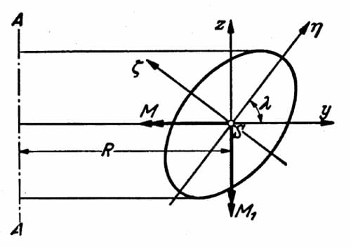
Figure 3.5: cross section of a thin ring showing absolute and principal axes [7]
The curvature can be projected onto the principal axes (η, ζ) with components kζ and kζ, respectively, and the curvature of the undeformed center line is 1/R. As such, the components of the change in curvature of the centerline of the ring, Δkη and Δkζ, due to toroidal deformation at angular position φ can be defined as
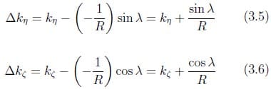
where R is the distance from the axis of the ring to the centroid of the cross section and λ is the angle between the y- and z-axes and the η- and ζ-axes.
Theory of beams with small initial curvature shows that the bending moments in a cross section at angular position φ are the product of the component changes in
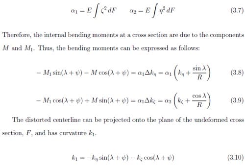
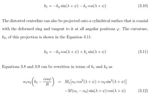
where W is the toroidal moment at angular position φ and αt is the torsional rigidity of the cross section at the same angular position. Equation 3.14 is strictly valid only for straight bars, but it is a reasonable assumption for n greater than 2. Integration of Equation 3.14 yields an expression for the toroidal angle,
where R is the distance from the axis of the ring to the centroid of the cross section, and k1 and k2 are expressions of the ring’s curvature. Substitution of Equation 3.15 into Equations 3.12 and 3.13 provides expressions for k1 and k2 needed to integrate Equations 3.16 and 3.17. Complete integration of Equations 3.16 and 3.17 yields
Substitution of Equations 3.4 and 3.15 into Equations 3.12 and 3.13, and Equa- tions 3.12 and 3.13 into Equation 3.22 yields a system of two equations with two unknowns, 0 and W0. This system of equations is used to determine the toroidal angle at the cross sections of the applied moments [7], and afterward the toroidal angle at every angular position φ can be calculated using Equation 3.15. An example of these results is shown in Figure 3.6.
From this point, the axial deflection of the ring can be determined using the calculated toroidal angle for each angular position φ and the initial ring surface geometry. Assuming pure rotation about the centroid of the cross section, the axial deflection due to workholding, δwh, at any point on the ring surface is expressed by

where z1 is the initial axial distance of the point from the centroid of the cross section, z2 is the final axial distance of the point from the centroid of the cross section, y1 is the initial radial distance of the point from the centroid of the cross section, and φ is the toroidal angle of the axial cross section at angular position φ (see Figure 3.7). It is assumed that the moment applied to the ring to achieve the angular rotation shown in Figure 3.7 is opposite in direction to the applied moment shown in Figures 3.3 and 3.4. The direction of rotation is assumed to be outward due to the radial direction of the clamping force applied to the thin ring by the internal chuck jaws. These axial deflections are added to the initial cast surface profile to obtain the clamped surface profile.
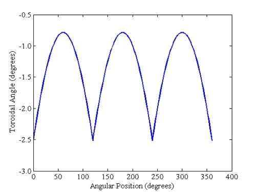
Figure 3.6: Toroidal angle vs. angular position for W0 = 500 N-m, R = 39.8 mm
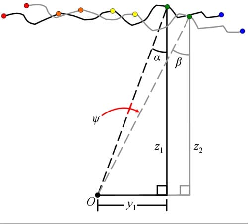
Figure 3.7: Geometry used to calculate axial deflection of ring due to toroidal deformation
3.1.2 Material Removal
The material removal model component assumes the point on the outer diameter of the clamped surface profile with the greatest axial dimension to be the axial machining zero. An equation corresponding to m
aterial that should be removed to achieve the desired surface profile is developed. For the mechanical seal in question, the assumed cutting profile is a 1.03° taper cut (measured from the horizontal) across the axial face of the ring. The corresponding material removal expression is shown in Equation 3.24, where r is the radius of the ring. The application of this equation produces the desired taper cut across the face of the ring, as shown in Figure 3.8. The results of this expression are subtracted from the clamped surface profile to obtain the material removal surface profile.
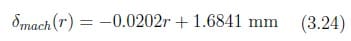
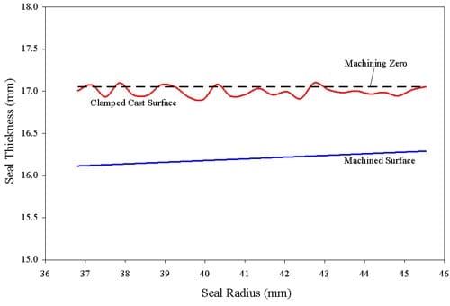
Figure 3.8: Representation of taper cut across seal surface
3.1.3 Workpiece Deflection due to Cutting Forces
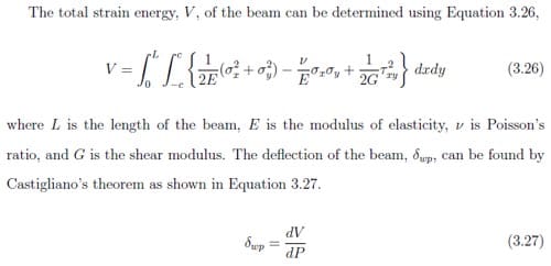
The model component for workpiece deflection due to cutting forces was developed using Castigliano’s theorem for a cantilever beam [8]. The cross section of the curved beam is assumed to act as a short, stubby cantilever loaded by a force P as shown in Figure 3.9. The normal and shear stress components in the beam are expressed in Equation 3.25,
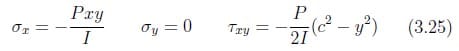
where P is the applied load, x and y are the respective x- and y-axis coordinates, I is the moment of inertia of the cross section, and c is the distance from the neutral plane of the beam. It is noted that the x- and y-axes and coordinates shown in Figure 3.9 and Equation 3.25 correspond to the y- and z-axes and coordinates, respectively, discussed in Section 3.1.1 and throughout the rest of this work.
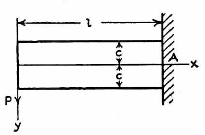
Figure 3.9: Schematic of cantilever loaded at free end [8]
For a ring of non-uniform cross section, the moment of inertia of the ring cross section is not constant. Thus, the ring cross section is assumed to have unit depth and can be divided into smaller subsections in which the moment of inertia can be considered constant or can be approximated as a first or second order function of the beam length. Because the cross section is assumed to have constant depth, the “height” of the beam cross section must be examined to determine the subsection divisions. The analyzed mechanical seal was divided into four subsections, shown in Figure 3.10, for which the moment of inertia could be expressed as constants and linear functions of the longitudinal beam dimension. The corresponding expressions of the moment of inertia are as follows,
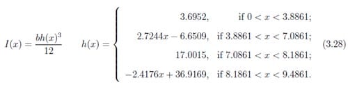
Similarly, the integral in Equation 3.26 must be divided into the same number of subsections and evaluated accordingly. Application of Castigliano’s theorem yields the deflections of the workpiece due to cutting forces. These axial workpiece deflections are added to the material removal surface profile to obtain the resulting machined surface profile.
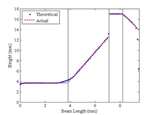
Figure 3.10: Representation of ring cross section for calculation of moment of inertia
3.1.4 Elastic Recovery due to Unclamping
The elastic recovery model component employs toroidal angles that are equal in magnitude and opposite in direction to those determined with the elastic deformation component of the general model. The elastic recovery model assumes that the machined cross section has the same centroid as the initial undeformed cross section F. The axial deflection of elastic recovery of the ring due to unclamping can be determined with the toroidal angles calculated for each angular position ‘ and the machined ring surface geometry. Assuming pure rotation about the centroid of the cross section, the axial deflections of elastic recovery, δrec, are expressed in Equation 3.29,

where z1 is the initial axial distance of the point from the centroid of the cross section, z2 is the final axial distance of the point from the centroid of the cross section, y1 is the initial radial distance of the point from the centroid of the cross section, and ψ is the toroidal recovery angle of the axial cross section at angular position φ (see Figure 3.11). The elastic recovery components are added to the machined surface profile to obtain the final surface profile.
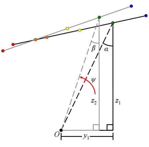
Figure 3.11: Geometry used to calculate axial deflection of ring due to elastic recovery
3.1.5 Determination of Peak-to-Valley Surface Profile Variation
The final PTV surface profile variation of the ring is determined from the final axial surface profile coordinates using Equation 3.30.

Figure 3.12 also describes the overall process used to determine the final PTV surface profile variation of the ring. While the final PTV surface profile variation is of primary importance to this work, the PTV surface profile variation of the ring may also be calculated at each intermediate step using similar methodology. These intermediate PTV surface profile variation measurements are integral to the evaluation of the model at each stage of the facing process.
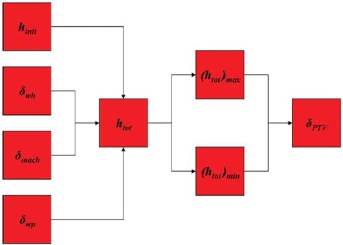
Figure 3.12: Flowchart describing calculation of final PTV surface profile variation importance to this work, the PTV surface profile variation of the ring may also be calculated at each intermediate step using similar methodology. These intermediate PTV surface profile variation measurements are integral to the evaluation of the model at each stage of the facing process.
3.1.6 Typical Results of Analytical Model
The general model developed to predict the final PTV surface profile variation for a facing operation of metallic rings of non-uniform cross section accounts for initial surface profile variation, elastic deformation due to workholding, material removal, workpiece deflection due to cutting forces, and elastic recovery due to unclamping. The rings had an inner diameter of 36.3 mm, an outer diameter of 46.04 mm, and a thickness of approximately 17 mm. The assumed modulus of elasticity and Poisson’s ratio of the ring material were 223 GPa and 0.3, respectively. The final PTV surface profile variation was calculated for a variety of workholding and machining conditions. Typical results for the analytical model are shown in the form of contour plots in Figure 3.13, and complete results are presented in Table 3.1. The first contour plot displays the uneven initial cast profile of the mechanical seal face. There is a decrease in PTV surface variation between the initial and the clamped surfaces which is indicative of the outward bending of the ring due to out-of-plane chucking forces. The third contour plot shows the uniform profile variation imparted to the ring by t
he machining of a taper. There is also an increase in PTV surface variation between the machined and final surfaces. This is indicative of the elastic recovery that occurs when the ring is unclamped.
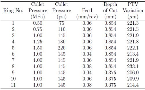
Table 3.1: Final PTV surface profile variation for workholding and machining conditions
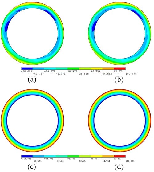
Figure 3.13: Typical results of analytical model for (a) initial, (b) clamped, (c) machined, (d) and final surface profiles; P = 1.00 MPa, f = 0.08 mm/rev, d = 0.854 mm, S = 100 m/min
3.2 Finite Element Model
Upon completion of the analytical model, a finite element model was created to determine the input components of the general surface profile model. Application of finite element method allowed for the relaxation of some analytical model assumptions and a more accurate prediction of the final PTV surface variation of the ring. In contrast to the toroidal moments applied at n equal angular intervals around the ring, the finite element model applied clamping loads via radial displacement of the chuck jaws in a manner similar to the physical mechanism of internal mechanical chucking. The finite element model also included contact elements to accurately approximate the resulting contact between the chuck jaws and the ring. Where the analytical model assumed uniform stiffness at all angular positions about the ring, the finite element model captures the effects of angular position on the stiffness of the ring-chuck assembly during the application of machining loads and the calculation of their resulting workpiece deflections. All other assumptions from the analytical model remain unchanged. As such, these relaxed assumptions yield a more realistic approximation of the interactions between the ring, mechanical chuck, and machine tool during workholding and machining.
3.2.1 Geometry and Material Model
The finite element model was built by importing a 3D solid model into ANSYS® 11.0. The solid model was an assembly of both the ring and a section of the chuck jaws, as shown in Figure 3.14. All solid model volumes were deleted, and the ring and jaw cross sections were created using the ANSYS® APDL programming language.
The complex ring-cross section shape was first approximated by straight lines as shown in Figure 3.15. The original cross section shape is represented in the figure by dashed lines, and the approximate cross section shape is represented by solid lines. Next, the cross section was divided into smaller areas, as shown in Figure 3.16. These two operations allow for greater control of the mesh to be applied to the ring cross section. The chosen cross section area divisions were meshed with a 2D meshing facet (MESH200). The meshing facet is a “mesh-only” element that contributes nothing to the finite element solution. It is recommended for multi-step meshing operations, like extrusion, in which a lower dimensionality mesh (i.e. 2D) is used to create a higher dimensionality mesh (i.e. 3D). A representative ring cross section facet mesh is shown in Figure 3.17.
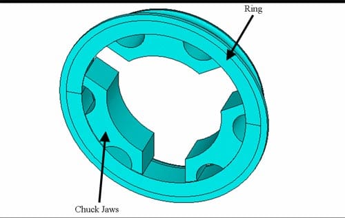
Figure 3.14: Solid model assembly of Stellite ring and chuck jaw sections
Next, the ring volume was created by revolving the cross section mesh about the ring axis using the VROTAT command. Command settings were chosen to produce a 360° extrusion of the cross section in six segments with elements formed every 3°.
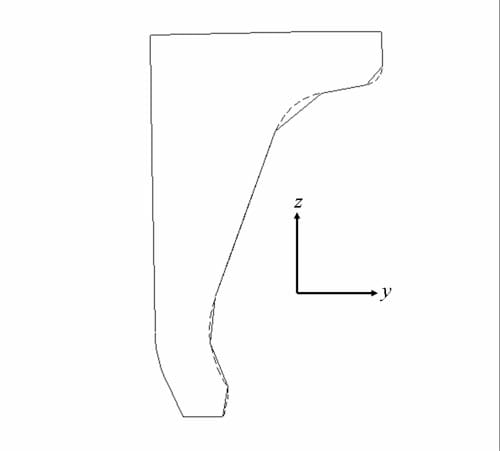
Figure 3.15: Approximation of ring cross section using straight lines
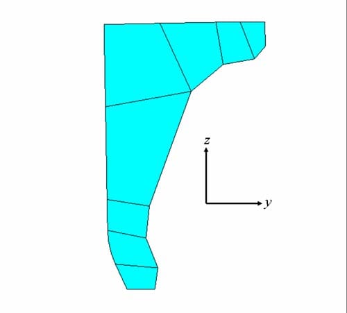
Figure 3.16: Ring cross section divided into mesh areas
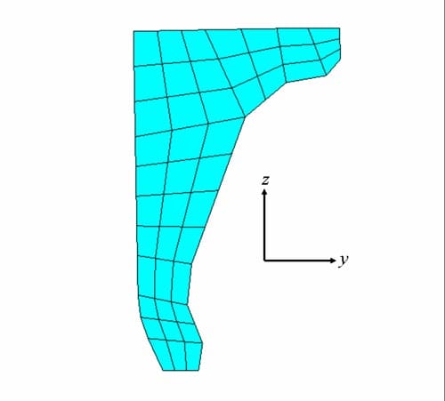
Figure 3.17: Representative ring facet mesh
Because deflections of the chuck jaw are not of primary importance to the finite element model solution, the chuck jaw cross section was left in its original state and meshed with a 2D meshing facet (MESH200). A representative jaw cross section facet mesh is shown in Figure 3.18. The jaw volumes were created by extruding the jaw cross section facet mesh parallel to the ring axis. Note that only the portions of the chuck jaws that contact the ring were modeled. The ring and jaw volumes were meshed with 3D brick elements (SOLID185), and this mesh is shown in Figure 3.19. The 3D brick element is defined by eight nodes having three degrees of freedom at each node { translations in the nodal x, y, and z directions. The final meshed ring had an inner radius of 36.320 mm, an outer radius of 45.948 mm, and a total thickness of 16.0 mm. The final meshed chuck jaws had an inner radius of 25.400 mm, an outer radius of 36.297 mm, and a total thickness of 15.392 mm.
Furthermore, contact (CONTA174) and target elements (TARGE170) were mod- eled at the interface between the ring and the chuck jaw sections to simulate friction between the surfaces of the respective materials. Contact elements are used to rep- resent contact and sliding between 3D “target” surfaces and a deformable surface. Contact elements overlay the solid elements that create the boundary of a deformable body and are potentially in contact with the target surface. Target elements are used to represent 3D “target” surfaces for the associated contact elements. The target sur- face is divided by a set of target segment elements and is paired with its associated contact surface via a shared real constant set. For this analysis, the outer diameter of the chuck jaws was chosen as the contact surface, and the inner diameter of the ring was chosen as the target surface. Contact and target elements were defined using the contact wizard in ANSYS® 11.0.

Figure 3.18: Representative chuck jaw facet mesh
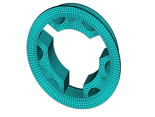
Figure 3.19: Ring and chuck jaw sections meshed with SOLID185
The ring and chuck jaw sections are assumed to be linear elastic materials. The ring is a cobalt alloy, Stellite, and the chuck jaws are made of tool steel. Their relevant material properties are shown in Table 3.2.
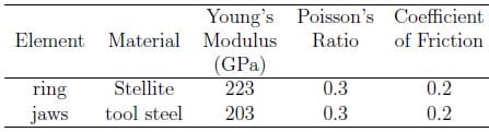
Table 3.2 – Material properties of ring and chuck jaw sections
3.2.2 Boundary Conditions
In order to obtain a static solution for the clamped surface profile of the ring and jaw assembly, nodes on the bottom face of the jaw sections were constrained in the axial and circumferential directions. A fixed displacement must be applied in the radial direction to simulate actual chuck jaw movement. Consequently, a series of finite element analyses were run to determine the exact correlation between radial node displacement and jaw clamping loads. Radial node displacements (10 { 50 μm) were applied to the bottom face of the chuck jaw sections, and a finite element solution was obtained. Radial displacements were applied only to the bottom faces because they are the cut boundary between the modeled portion of the chuck jaw and the remainder of the moving collet chuck. Contac
t forces were retrieved from the model solution and summed for each chuck jaw, and the clamping force magnitudes were averaged over the three jaws. The developed correlation is displayed in Figure 3.20 and expressed in Equation 3.31.
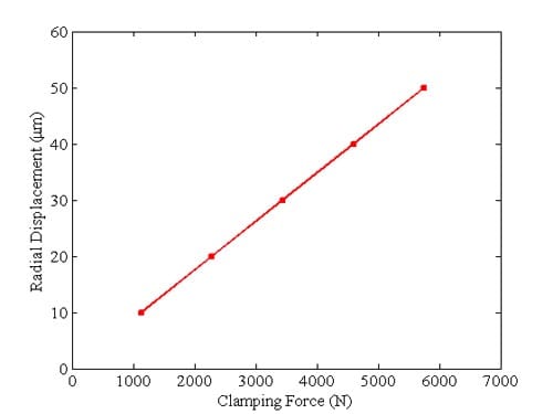
Figure 3.20: Correlation between radial displacement and jaw clamping force
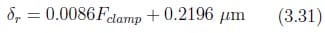
The correlation was used to apply appropriate nodal displacements given experimentally measured jaw clamping forces (see Chapter 4). The nodes on the bottom face of the ring were also fixed to zero displacement in the axial and circumferential directions. The overall assumption of these boundary conditions is that the ring is held flat against the chuck and does not slide about its axis during chucking.
To obtain a solution for the machined surface profile of the ring, average thrust forces due to cutting were applied to each surface node in independent load steps, while all other boundary conditions remained the same. The thrust force is the component of the machining load that is perpendicular to the axial seal face during turning. This application of cutting forces is similar to the finite element analysis technique used by Masset and Debongnie [26]. The thrust forces were obtained ex- perimentally as detailed in Chapter 4. The workpiece deflection due to the thrust loads was recorded as the axial deflection at each node as the thrust force was applied to that node only.
3.2.3 Convergence Study
The geometry of a finite element model is divided into many discrete elements. This approximation of the model geometry introduces inherent numerical error into the finite element solution. This error should decrease with increasing mesh density for a robust finite element model as model deflections and reaction forces converge to a final value. It is also desirable to balance model accuracy with required solution time. Consequently, a convergence study was performed to determine an adequate mesh size for the finite element model. Mesh size was altered with the ESIZE command for a range of 0.5 – 3.0 mm.
The average axial displacement of a small area along the outer diameter of the ring was observed for each mesh size, and the results are shown in Figures 3.21. The axial displacement solution does not vary significantly over the range of mesh sizes studied, and the finite element solution is considered to be sufficiently converged. Consequently, an element size of 2 mm was chosen for appropriate model accuracy and reasonable solution time.
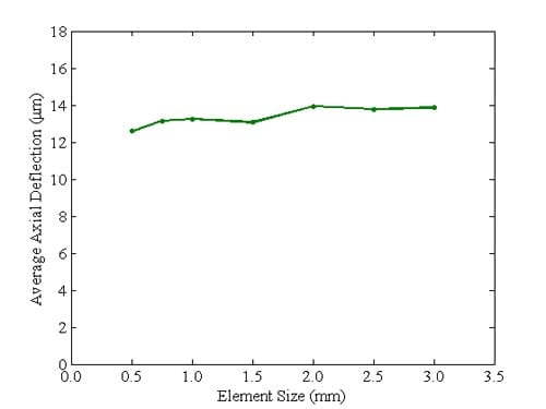
Figure 3.21: Mesh convergence study results, outer diameter
3.2.4 Friction Sensitivity Analysis
Analysis was performed to determine the sensitivity of model results to the coefficient of friction at the clamp-workpiece interface. Displacement results for coefficients of friction ranging from 0.1 to 0.5 are shown in Figure 3.22. Figure 3.22 clearly shows that the deflection of the workpiece due to workholding varies linearly with the coefficient of friction. Furthermore, the deflection varies less than five percent between each respective coefficient of friction value. Consequently, a coefficient of friction of 0.2 was chosen. This value is comparable to coefficients of friction between two Stellite surfaces determined experimentally in the literature [36, 37].
3.2.5 Typical Results of Finite Element Model
A finite element model that includes a Stellite ring and three chuck jaw sections was built using ANSYS® 11.0. Deflection results obtained from the model were input into the general model (Equation 3.1) to obtain the final PTV surface profile variation reflected by the finite element analysis. Typical results for the finite element model are displayed in the form of contour plots in Figure 3.23, and complete results are presented in Table 3.3. The first contour plot displays the initial profile of the mechanical seal face that was applied to the finite element model. There is a trend of outward bending between the initial and the clamped surfaces which is indicative of the outward bending of the ring due to out-of-plane chucking forces. The elastic deformation due to workholding displays one-third symmetry as is expected for loading by three evenly spaced chuck jaws. The third contour plot shows the even profile variation imparted to the ring by machining of a taper. Again, there is an increase in PTV surface variation between the machined and final surfaces. This is indicative of the elastic recovery that occurs when the ring is unclamped.
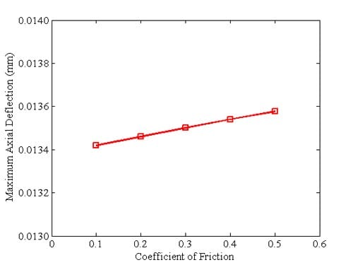
Figure 3.22: Coefficient of friction sensitivity analysis results
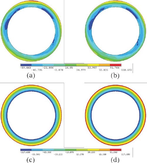
Figure 3.23: Typical results of finite element model for (a) initial, (b) clamped, (c) machined, (d) and final surface profiles; P = 1.00 MPa, f = 0.08 mm/rev, d = 0.854 mm, S = 100 m/min
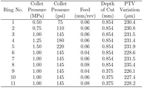
Table 3.3: Final PTV surface profile variation from finite element model
3.3 Summary
In this chapter, an analytical model was developed to predict the final out-of-plane PTV surface profile variation of the face of a thin ring as a result of workholding and cutting loads applied during a facing operation. Additionally, a finite element model was developed to relax several analytical model assumptions and provide a more accurate prediction of the same PTV surface profile variation of the thin ring. A mesh convergence study was conducted to determine the required element size for adequate resolution of the nodal deflection solution. Both the analytical and finite element models were applied to a ring with inner and outer radii of 36.3 mm and 46.04 mm, respectively, and a thickness of 17 mm.
In general, the analytical and finite element model predictions of the final PTV surface profile variation correspond reasonably well. The analytical model predicts final PTV surface profile variations in the range of 206.0 { 222.1 μm while the finite element model predicts final PTV surface profile variations in the range of 226.1 – 231.9 μm. Discrepancies between the analytical and finite element models result primarily from the inability of the analytical model to include variations in rigidity of the ring-jaw assembly due to angular position around the ring. This results in analytical workpiece deflections due to cutting loads that are a function of radial position and are independent of angular position.
Experimental Verification
Three series of experiments were completed to verify the developed analytical and finite element models. The first series of experiments examined the peak-to-valley (PTV) surface profile variation of a set of Stellite rings before and after each phase of the facing process. Surface profile variation was measured in its initial form, after clamping only (before facing), after facing (while clamped), and in its final unclamped form. The second series of experiments characterized the clamping force produced by the three-jaw chuck for a range of lathe collet pressure settings. The third series of experiments involved measuring the cutting forces applied to the workpiece during the facing operation. Cutting force experiments were performed
for a range of machining parameters. A detailed discussion of each of these series of experiments is presented below.
4.1 Surface Profile Variation Measurement
Two experimental designs were created to explore the effects of collet pressure and machining process parameters on final PTV surface profile variation. The first exper- imental design, shown in Table 4.1, varies collet pressure and uses constant nominal machining process parameters. The second experimental design, shown in Table 4.2, uses a constant collet pressure and varies machining process parameters. The ring seal face had an inner radius of 36.3 mm and an outer radius of 46.04 mm, and each surface profile was measured at five ring radii: 36.808 mm, 38.989 mm, 41.170 mm, 43.351 mm, and 45.532 mm. The consideration of all five radii provides a reasonable representation of the entire ring surface profile variation.
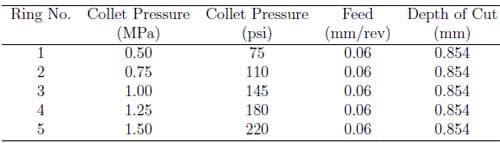
Table 4.1: Experimental design to explore the effect of collet pressure
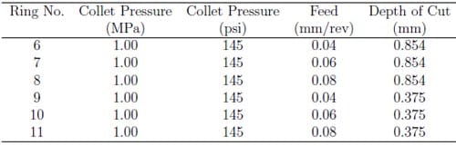
Table 4.2: Experimental design to explore the effect of machining process parameters
4.1.1 Initial Peak-to-Valley Surface Profile Variation
The initial PTV surface profile variation was measured on a coordinate measuring machine (Brown and Sharpe MicroVal PFx) with a resolution of 0.01 mm. Clay was used to fix the mechanical seals to the CMM table. This setup is shown in Figure 4.1. Surface profile coordinates were recorded along the five seal radii at three degree increments around the entire circumference of the seal. PC-DMIS 4.2 was used to program and record the CMM measurements.
4.1.2 Clamped Peak-to-Valley Surface Profile Variation
The clamped PTV surface profile variation was measured using a Mahr Extramess 2001 inductive digital comparator at a resolution setting of 0.5 μm. Each ring was clamped in a three-jaw chuck (Howa H037-M8). The inductive digital comparator was mounted to a magnetic base, as shown in Figure 4.2, and the clamped surface profile was measured by rotating the spindle of a Hardinge Conquest T42SP turning center at approximately 1 rpm and recording the surface profile measurement at fixed time increments via an RS232 cable. The inductive digital comparator was equipped with a 12 mm diameter carbide spherical contact point to minimize noise due to cast surface roughness.
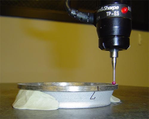
Figure 4.1: Experimental setup for measurement of initial PTV surface profile variation
4.1.3 Machined Peak-to-Valley Surface Profile Variation
A Hardinge Conquest T42SP turning center was used to face the Stellite rings. Each ring was machined using the parameters displayed in Tables 4.1 and 4.2 and a high grade cBN cutting insert (90% carbide content) type SCG-312(3) (Mastertech Diamond Products Company). The machined PTV surface profile variation was measured using the same Mahr Extramess 2001 inductive digital comparator. Each ring was measured immediately after facing while clamped in the three-jaw chuck (Howa H037-M8). The digital comparator was again mounted to a magnetic base, and the clamped surface profile was measured by rotating the spindle of the lathe at approximately 1 rpm and recording the surface profile measurement at fixed time increments via an RS232 cable. The inductive digital comparator was equipped with a 1 mm diameter carbide ball contact point for these measurements.
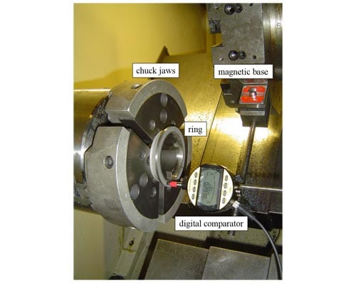
Figure 4.2: Experimental setup for measurement of clamped PTV surface profile variation
4.1.4 Final Peak-to-Valley Surface Profile Variation
The final PTV surface profile variation was measured on the same coordinate mea- suring machine (Brown and Sharpe MicroVal PFx) with a resolution of 0.01 mm, and clay was used to fix the mechanical seals to the CMM table. Surface profile coordinates were recorded along the five seal radii at three degree increments around the entire circumference of the seal. PC-DMIS 4.2 was used to program and record the CMM measurements. Typical experimental results are displayed in the form of contour plots in Figure 4.3. The initial, clamped, machined, and final PTV surface profile variations of each ring are shown in Table 4.3.

Figure 4.3: Typical experimental results for (a) initial, (b) clamped, (c) machined, (d) and final surface profiles; P = 1.00 MPa, f = 0.08 mm/rev, d = 0.854 mm, S = 100 m/min
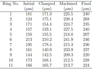
Table 4.3: Peak-to-valley surface profile variations for Stellite rings
4.2 Clamping Force Measurement
The clamping force produced by the Howa H037-M8 chuck was measured using Pressurex® pressure sensitive film. In order to capture the full magnitude of the clamping force, three ranges of pressure sensitive film were used: low (350-1,400 psi), medium (1,400-7,100 psi), and high (7,100-18,500 psi). Upon the application of force, the pressure film releases red ink to create a permanent color image of the applied pressure map. The color intensity of the film is quantifiable and can be correlated to the applied pressure and force.
A strip of low pressure sensitive film was placed between two thin stainless steel mounting brackets, and a mounting bracket was fixed to each chuck jaw. The mount- ing brackets were used to concentrate the clamping force transmission through a single contact area for each chuck jaw. This process was repeated for both the medium and high pressure sensitive films at each collet pressure setting.
A representative strip of used Pressurex® film is shown in Figure 4.4. Each strip of pressure film was scanned as a grayscale image and the affected portions of the film were isolated for further analysis, as shown in Figure 4.5.
Figure 4.4: Scanned grayscale image of pressure sensitive film

Figure 4.5: Image of isolated pressure region
The isolated pressure region images were analyzed using MATLAB® software, and a pressure value was assigned to each pixel using correlations provided by the manufacturer. Each of these pressure values were multiplied by the pixel area and summed over the entire image to calculate the total clamping force for each pressure film strip. The force values obtained for the low, medium, and high pressure sensitive film types were combined to determine the total clamping force for each jaw at each collet pressure setting. These results are presented in Table 4.4.

Table 4.4: Peak-to-valley surface profile variations for Stellite rings
4.3 Cutting Force Measurement
Cutting force experiments were performed to determine the average cutting forces applied to the workpiece during the facing operation. Stellite rings were faced on a Hardinge Conquest T42SP turning center. A tool holder (T&A Tool MSDNN-16B) was mounted on the outer face of a cutting force dynamometer (Kistler 9257B) using a steel bracket with si
x hexagonal head screws that joined the bracket to the top plate of the dynamometer. The dynamometer was mounted on the turret of the Hardinge CNC turning center.
The rings were faced with a cBN cutting insert type SCG-312(3). An experimental design with two levels of depth of cut (0.375 mm and 0.845 mm) and three levels of feed (0.04 mm/rev, 0.06 mm/rev, and 0.08 mm/rev) was used to characterize the average cutting forces, and three replicates were performed for each treatment. Cutting forces were measured with the cutting force dynamometer and were sampled at 1000 Hz. A data acquisition system (National Instruments) was used to record the three component output signals via a three channel Kistler charge amplifier. Figure 4.6 displays a typical result obtained by the data acquisition system.
The thrust force is of primary importance because it is the component of the resultant machining force that causes axial workpiece deflection during cutting. The steady state portion of each thrust force measurement was averaged to determine the thrust force for each facing operation. These results are displayed in Table 4.5.
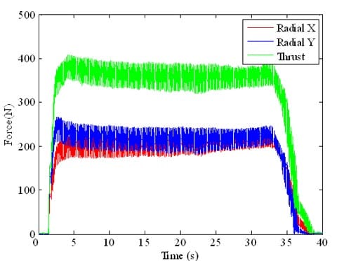
Figure 4.6: Dynamometer results for facing operation: f = 0.06 mm/rev, d = 0.845 mm
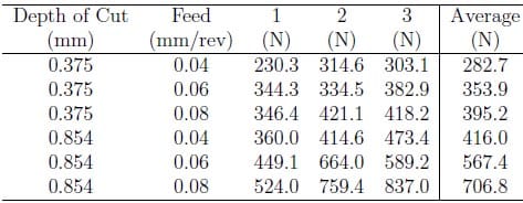
Table 4.5: Average thrust forces for facing operation
4.4 Results and Discussion
The measured PTV surface profile variations were compared with the analytical and finite element PTV surface profile variation results described in Chapter 3. This comparison is shown in Table 4.6.
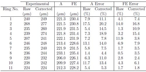
Table 4.6: Comparison of analytical (A) and finite element (FE) final PTV surface profile variation to experimental data
Note that the analytical and finite element data are compared to the experimental data in its raw and corrected forms. A small chamfer was cut into the inner and outer diameters of the mechanical seals during facing. The chamfer allowed the cutting tool to engage the mechanical seal gradually during facing in order to minimize engage- ment chatter and to maximize tool life. During final surface profile measurement, the positional error of the CMM probe tip and the presence of the chamfer would sometimes result in a misleading surface profile measurement at the inner or outer diameter of the seal. The misleading measurements occurred in the form of profile discontinuities that did not represent the true shape of the machined taper profile. In many cases, this discontinuity resulted in underestimation of the final PTV surface profile variation of the mechanical seals. Thus, a linear fit was applied to the remain- der of the final surface profile coordinates and the affected inner or outer diameter coordinate was corrected” with this linear fit. A representative data correction plot is shown in Figure 4.7 with both the raw and corrected linear surface profiles.
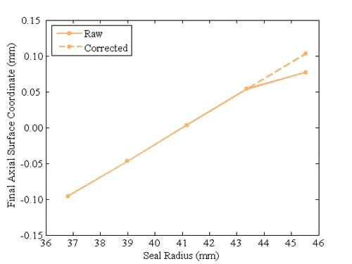
Figure 4.7: Representative depiction of raw and corrected final surface profiles
It is clear that the final PTV surface profile variations predicted by the analytical model and the finite element model agree quite well with the measured final PTV surface profile variations. The average relative error of the analytical model is 8.1 per- cent when compared to the raw experimental data and 11.6 percent when compared to the corrected experimental data. The average relative error of the finite element model is 4.8 percent when compared to the raw experimental data and 7.2 percent when compared to the corrected experimental data.
Comparison of the final analytical and finite element PTV surface profile variations to the final experimental PTV surface profile variation provides a robust evaluation of the overall performance of the two models. However, further examination is required to determine the strengths and weaknesses of the intermediate components of the analytical and finite element models. Comparison of the initial PTV surface profile variations is not necessary because the same initial profile was applied to both the analytical and finite element models.
The experimental clamped PTV surface profile variations are compared with the analytical and finite element clamped PTV surface profile variation results in Ta- ble 4.7. The average relative error of the analytical model is 8.1 percent when compared to the experimental data, and the average relative error of the finite element model is 11.7 percent when compared to the experimental data. This result is not intuitive because the finite element model relaxes some of the assumptions of the analytical model. Specifically, it accounts for workpiece stiffness variation with re- spect to angular and radial position in the determination of elastic deformation due to workholding. As such, it should provide a more accurate prediction of the clamped PTV surface profile variation than the analytical model. One possible explanation for this discrepancy is the use of linear interpolation to apply the initial surface profile to the finite element model. Linear interpolation and extrapolation were employed to determine initial surface profile values at finite element node coordinates that existed between and outside of experimentally measured coordinates, respectively. Consequently, error was introduced at this intermediate step in the finite element model because the initial surface profile variation of each ring does not conform to a strictly linear relation.
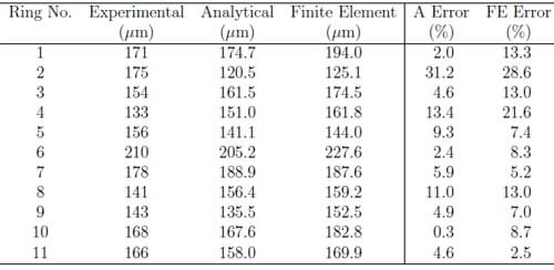
Table 4.7: Comparison of analytical and finite element clamped PTV surface profile variation to experimental data
The relatively large errors in the analytical and finite element predictions of the clamped PTV surface profile variation of ring two are also noted. Ring two was the only ring that displayed an experimental clamped PTV surface profile variation that was larger than its experimental initial PTV surface profile variation. Variations in the geometry and material composition of the ring may have caused this behavior. Deviations such as cast internal voids could cause a shift of the ring cross section centroid such that the ring might display workholding deflection behavior opposite of that predicted by the analytical and finite element models and exhibited by other experimentally measured rings. Despite these error sources, both the analytical and finite element models correspond reasonably well to the experimental clamped PTV surface profile variation.
The experimental machined PTV surface profile variations are also compared with the analytical and finite element machined PTV surface profile variation results, as shown in Table 4.8. The average relative error of the analytical model is 8.3 percent when compared to the experimental data, and the average relative error of the finite element model is 3.6 percent when compared to the experimental data. The effects of the linear interpolation and extrapolation applied to the finite element surface are eliminated with the application of the material removal profile and the workpiece deflections due to machining loads. Consequently, the finite element model is more accurate than the analytical model in its prediction of the machined PTV surface profile variation. The contrast in accuracy between the two models is primarily due to the fact that the finite element model accounts for workpiece stiffness variations with respect to both angular and radial position in the calculation of workpiece deflect
ions due to machining loads, while the analytical model only accounts for stiffness variations with respect to radial position on the workpiece.
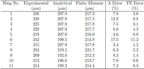
Table 4.8: Comparison of analytical and finite element machined PTV surface profile variation to experimental data
The analytical model assumption that workpiece stiffness varies only in the radial direction is the cause for identical analytical machined PTV surface profile variations determined for rings 1{5 and 7. These identical magnitudes reveal the chief limitation of the analytical model. Because it does not account for machining load variations due to depth of cut or workpiece stiffness variations with respect to angular position, the analytical model yields the same machined PTV surface profile variation for a given machining load regardless of other process parameters. The finite element model, however, yields a unique machined PTV surface profile variation magnitude for each unique combination of process parameters. Both the analytical and finite element models assume that machining loads do not vary radially with respect to depth of cut. In the current work, this assumption eliminates the effect of the initial PTV surface profile variation on the final PTV surface profile variation. However, in general, if the effect of the initial surface profile variation on the depth of cut and therefore on the machining force is taken into account, the initial profile error can affect the final PTV surface profile variation.
In addition to a comparison of the individual components of the analytical and finite element models, the impact of the respective process parameters on final PTV surface profile variation can also be explored. The effects of collet pressure, feed, and depth of cut on the final PTV surface profile variation of the machined rings are shown in Figures 4.8, 4.9, and 4.10, respectively. The data shown for the feed trend plot is the subset of the entire data set with a depth of cut of 0.375 mm, and the data shown for the depth of cut trend plot is the subset of the entire data set with a feed of 0.06 mm/rev. The analytical and finite element results display similar linearly increasing trends for each of the collet pressure, feed, and depth of cut trend plots.
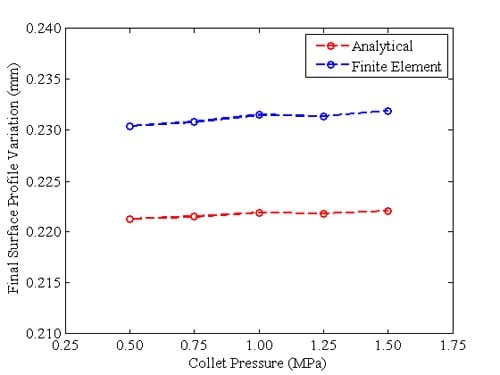
Figure 4.8: Effect of collet pressure on final PTV surface profile variation
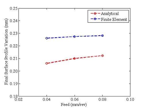
Figure 4.9: Effect of feed on final PTV surface profile variation
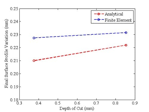
Figure 4.10: Effect of depth of cut on final PTV surface profile variation
Conclusions and Recommendations
5.1 Main Conclusions
This thesis presented an analytical method for prediction of the final peak-to-valley (PTV) surface profile variation caused in thin ring-shaped parts of non-uniform cross section subject to workholding and machining loads in a facing process. This model can be used to optimize workholding and cutting conditions so as to minimize the overall form error. Additionally, finite element analysis was carried out to relax some of the assumptions made in the development of the analytical model to provide a more accurate prediction of the final PTV surface profile variation. Furthermore, experiments were conducted to characterize the appropriate model inputs for face turning of cobalt rings. Consequently, the following conclusions can be drawn:
- The analytical model predicts the final PTV surface profile variation of the Stellite rings with reasonable accuracy. Errors range from 4.4 to 20.2 percent with a mean of 11.6 percent.
- The finite element model also predicts the final PTV surface profile variation of the Stellite rings with reasonable accuracy. Errors range from 1.8 to 16.8 percent with a mean of 7.2 percent.
- Each of the process variables, collet pressure, feed, and depth of cut, has a linearly increasing effect on the final PTV surface profile variation.
5.2 Recommendations and Future Work
The contribution of each of the model parameters shown in Equation 3.1 to the final PTV surface profile variation is unique depending on the applied machining process parameters. For instance, the final PTV surface profile variation for a process with large clamping loads would typically be dominated by the component of deflection due to workholding loads. Similarly, the final PTV surface profile variation for a process with excessive machining loads would typically be dominated by the component of deflection due to machining loads. These conclusions further indicate the complexity of the interaction of the components of de ection that comprise the general model.
Related areas for further research include the following:
- Investigation of toroidal deformation with non-uniform moments applied at specific cross sections.
- Development of an analytical model that accounts for workpiece stiffness due to angular position during workpiece deflection calculation and variation in machining loads due to depth of cut.
- Development of a finite element model that accounts for variation in machining loads due to depth of cut.
- Exploration of flexible fixtures to minimize workpiece deflections due to workholding loads.
- Optimization of machining parameters to minimize workpiece deflections due to machining loads.
This thesis examined the theoretical application of uniform clamping loads by each of the chuck jaws. Future research might explore the effect of non-uniform clamping loads applied by the chuck jaws, i.e. each chuck jaw applies a clamping load of a different magnitude. It might also explore the variation in clamping force applied by the chuck jaws during machining due to rotation.
The current analytical model does not account for variations in workpiece stiffness due to angular position in the calculation of workpiece deflections due to machining loads. It assumes that each angular position around the ring behaves like a cantilever. However, the chuck jaws do not contact the workpiece about the entire ring inner diameter. This assumption is not fully valid in the non-contact positions where internal shear and bending moments govern workpiece de ection. Furthermore, both the analytical and finite element models neglect the effects of machining load variations due to depth of cut on workpiece deflections during facing. Each of these items should be considered in future research to better predict final PTV surface profile variation in non-uniform cross section ring-shaped workpieces.
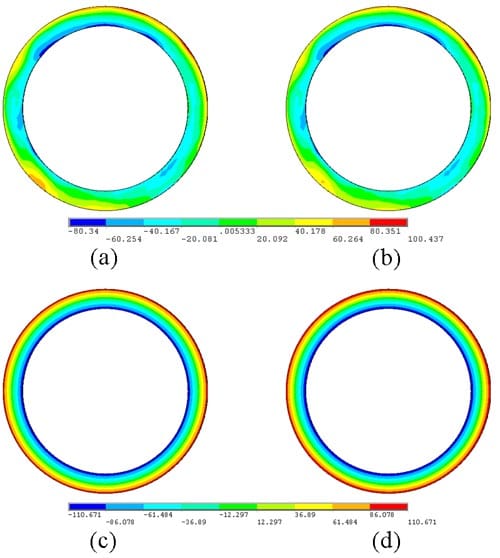
Figure A.1: Analytical results for (a) initial surface form profile, (b) clamped surface form profile, (c) machined surface form profile, (d) final surface form profile; P = 0.50 MPa, f = 0.06 mm/rev, d = 0.854 mm, S = 100 m/min
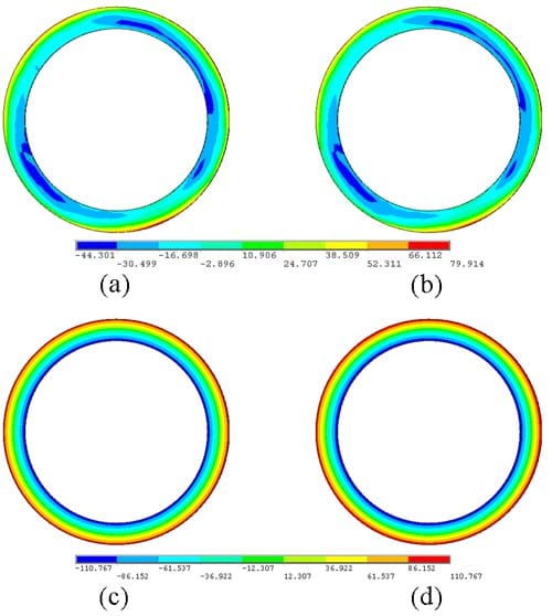
Figure A.2: Analytical results for (a) initial surface form profile, (b) clamped surface form profile, (c) machined surface form profile, (d) final surface form profile; P = 0.75 MPa, f = 0.06 mm/rev, d = 0.854 mm, S = 100 m/min
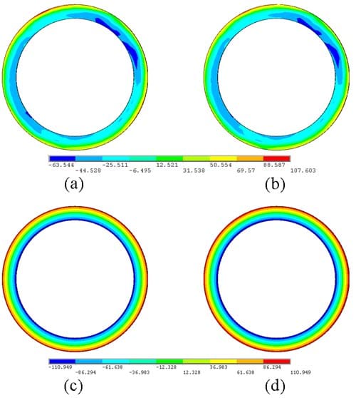
Figure A.3: Analytical results for (a) initial surface form profile, (b) clamped surface form profile
, (c) machined surface form profile, (d) final surface form profile; P = 1.00 MPa, f = 0.06 mm/rev, d = 0.854 mm, S = 100 m/min
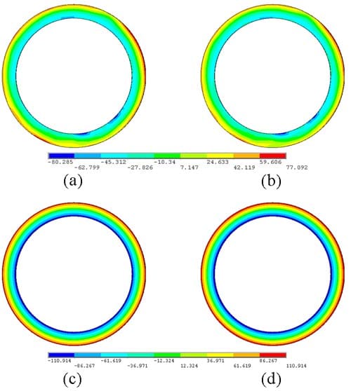
Figure A.4: Analytical results for (a) initial surface form profile, (b) clamped surface form profile, (c) machined surface form profile, (d) final surface form profile; P = 1.25 MPa, f = 0.06 mm/rev, d = 0.854 mm, S = 100 m/min
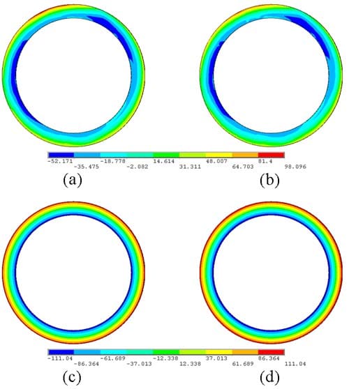
Figure A.5: Analytical results for (a) initial surface form profile, (b) clamped surface form profile, (c) machined surface form profile, (d) final surface form profile; P = 1.50 MPa, f = 0.06 mm/rev, d = 0.854 mm, S = 100 m/min
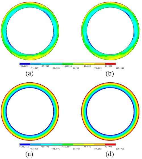
Figure A.6: Analytical results for (a) initial surface form profile, (b) clamped surface form profile, (c) machined surface form profile, (d) final surface form profile; P = 1.00 MPa, f = 0.04 mm/rev, d = 0.854 mm, S = 100 m/min
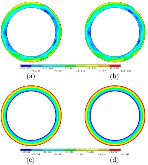
Figure A.7: Analytical results for (a) initial surface form profile, (b) clamped surface form profile, (c) machined surface form profile, (d) final surface form profile; P = 1.00 MPa, f = 0.06 mm/rev, d = 0.854 mm, S = 100 m/min
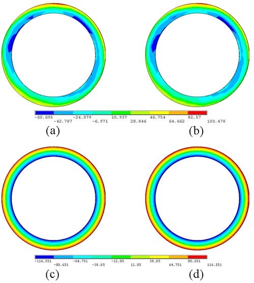
Figure A.8: Analytical results for (a) initial surface form profile, (b) clamped surface form profile, (c) machined surface form profile, (d) final surface form profile; P = 1.00 MPa, f = 0.08 mm/rev, d = 0.854 mm, S = 100 m/min
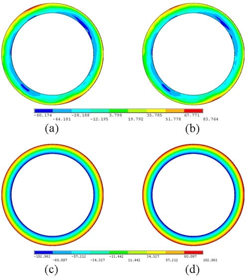
Figure A.9: Analytical results for (a) initial surface form profile, (b) clamped surface form profile, (c) machined surface form profile, (d) final surface form profile; P = 1.00 MPa, f = 0.04 mm/rev, d = 0.375 mm, S = 100 m/min
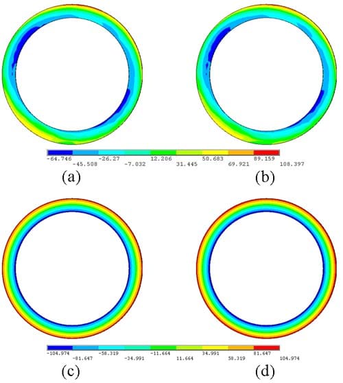
Figure A.10: Analytical results for (a) initial surface form profile, (b) clamped surface form profile, (c) machined surface form profile, (d) final surface form profile; P = 1.00 MPa, f = 0.06 mm/rev, d = 0.375 mm, S = 100 m/min
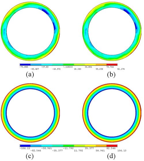
Figure A.11: Analytical results for (a) initial surface form profile, (b) clamped surface form profile, (c) machined surface form profile, (d) final surface form profile; P = 1.00 MPa, f = 0.08 mm/rev, d = 0.375 mm, S = 100 m/min
Finite Element Results
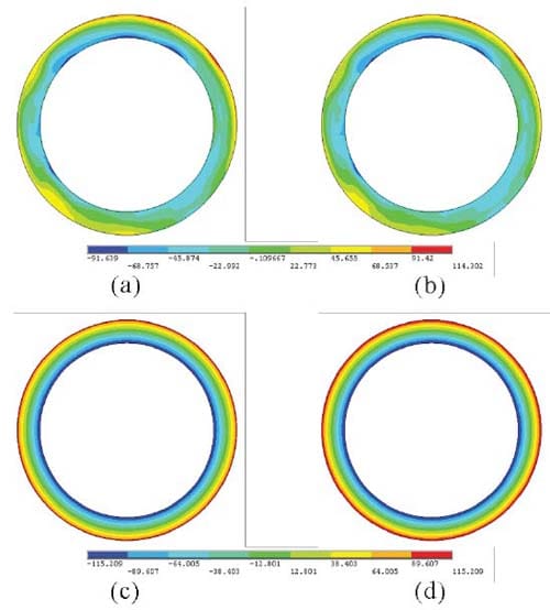
Figure B.1: Finite element results for (a) initial surface form profile, (b) clamped surface form profile, (c) machined surface form profile, (d) final surface form profile; P = 0.50 MPa, f = 0.06 mm/rev, d = 0.854 mm, S = 100 m/min
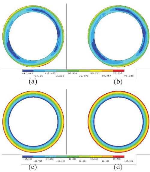
Figure B.2: Finite element results for (a) initial surface form profile, (b) clamped surface form profile, (c) machined surface form profile, (d) final surface form profile; P = 0.75 MPa, f = 0.06 mm/rev, d = 0.854 mm, S = 100 m/min
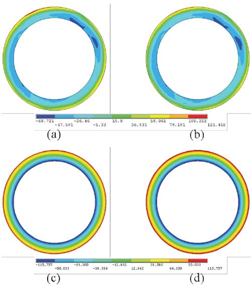
Figure B.3: Finite element results for (a) initial surface form profile, (b) clamped surface form profile, (c) machined surface form profile, (d) final surface form profile; P = 1.00 MPa, f = 0.06 mm/rev, d = 0.854 mm, S = 100 m/min
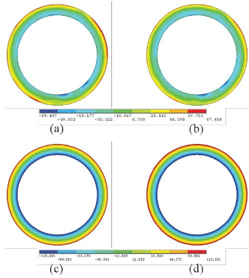
Figure B.4: Finite element results for (a) initial surface form profile, (b) clamped surface form profile, (c) machined surface form profile, (d) final surface form profile; P = 1.25 MPa, f = 0.06 mm/rev, d = 0.854 mm, S = 100 m/min
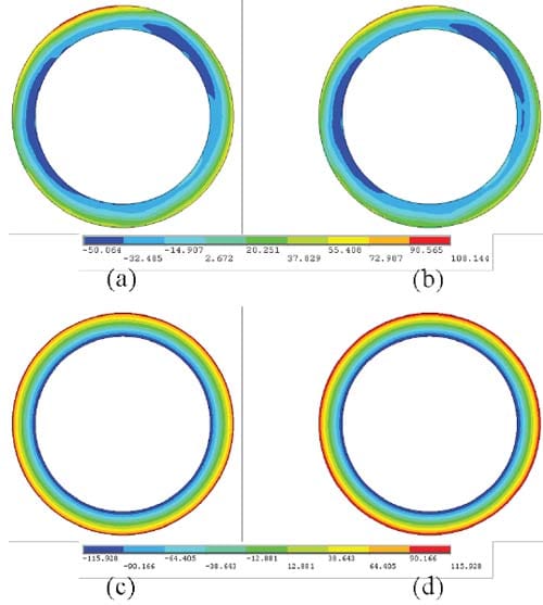
Figure B.5: Finite element results for (a) initial surface form profile, (b) clamped surface form profile, (c) machined surface form profile, (d) final surface form profile; P = 1.50 MPa, f = 0.06 mm/rev, d = 0.854 mm, S = 100 m/min
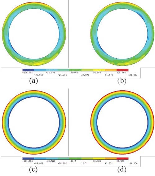
Figure B.6: Finite element results for (a) initial surface form profile, (b) clamped surface form profile, (c) machined surface form profile, (d) final surface form profile; P = 1.00 MPa, f = 0.04 mm/rev, d = 0.854 mm, S = 100 m/min
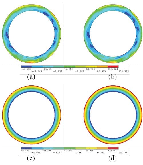
Figure B.7: Finite element results for (a) initial surface form profile, (b) clamped surface form profile, (c) machined surface form profile, (d) final surface form profile; P = 1.00 MPa, f = 0.06 mm/rev, d = 0.854 mm, S = 100 m/min
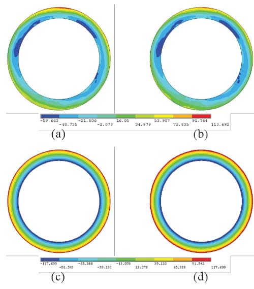
Figure B.8: Finite element results for (a) initial surface form profile, (b) clamped surface form profile, (c) machined surface form profile, (d) final surface form profile; P = 1.00 MPa, f = 0.08 mm/rev, d = 0.854 mm, S = 100 m/min
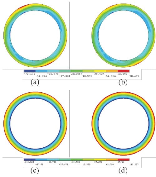
Figure B.9: Finite element results for (a) initial surface form profile, (b) clamped surface form profile, (c) machined surface form profile, (d) final surface form profile; P = 1.00 MPa, f = 0.04 mm/rev, d = 0.375 mm, S = 100 m/min
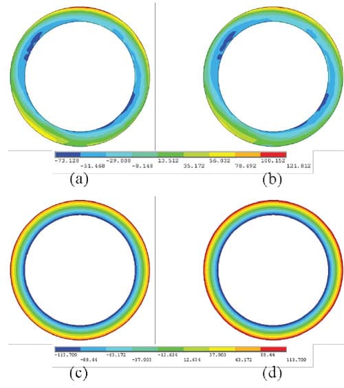
Figure B.10: Finite element results for (a) initial surface form profile, (b) clamped surface form profile, (c) machined surface form profile, (d) final surface form profile; P = 1.00 MPa, f = 0.06 mm/rev, d = 0.375 mm, S = 100 m/min
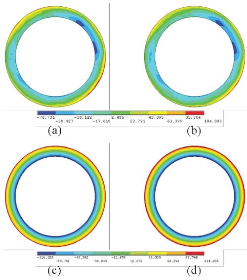
Figure B.11: Finite element results for (a) initial surface form profile, (b) clamped surface form profile, (c) machined surface form profile, (d) final surface form profile; P = 1.00 MPa, f = 0.08 mm/rev, d = 0.375 mm, S = 100 m/min
Experimental Results
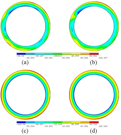
Figure C.1: Experimental results for (a) initial surface form profile, (b) clamped surface form profile, (c) machined surface form profile, (d) final surface form profile; P = 0.50 MPa, f = 0.06 mm/rev, d = 0.854 mm, S = 100 m/min
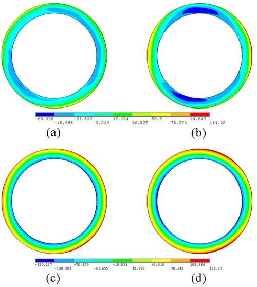
Figure C.2: Experimental results for (a) initial surface form profile, (b) clamped surface form profile, (c) machined surface form profile, (d) final surface form profile; P = 0.75
MPa, f = 0.06 mm/rev, d = 0.854 mm, S = 100 m/min
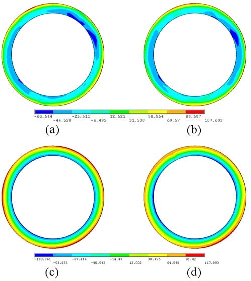
Figure C.3: Experimental results for (a) initial surface form profile, (b) clamped surface form profile, (c) machined surface form profile, (d) final surface form profile; P = 1.00 MPa, f = 0.06 mm/rev, d = 0.854 mm, S = 100 m/min
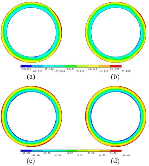
Figure C.4: Experimental results for (a) initial surface form profile, (b) clamped surface form profile, (c) machined surface form profile, (d) final surface form profile; P = 1.25 MPa, f = 0.06 mm/rev, d = 0.854 mm, S = 100 m/min
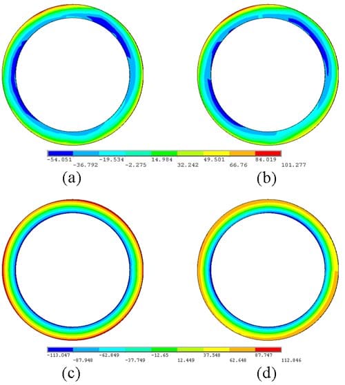
Figure C.5: Experimental results for (a) initial surface form profile, (b) clamped surface form profile, (c) machined surface form profile, (d) final surface form profile; P = 1.50 MPa, f = 0.06 mm/rev, d = 0.854 mm, S = 100 m/min
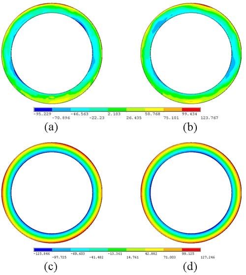
Figure C.6: Experimental results for (a) initial surface form profile, (b) clamped surface form profile, (c) machined surface form profile, (d) final surface form profile; P = 1.00 MPa, f = 0.04 mm/rev, d = 0.854 mm, S = 100 m/min
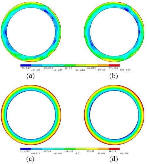
Figure C.7: Experimental results for (a) initial surface form profile, (b) clamped surface form profile, (c) machined surface form profile, (d) final surface form profile; P = 1.00 MPa, f = 0.06 mm/rev, d = 0.854 mm, S = 100 m/min
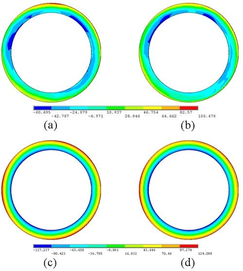
Figure C.8: Experimental results for (a) initial surface form profile, (b) clamped surface form profile, (c) machined surface form profile, (d) final surface form profile; P = 1.00 MPa, f = 0.08 mm/rev, d = 0.854 mm, S = 100 m/min
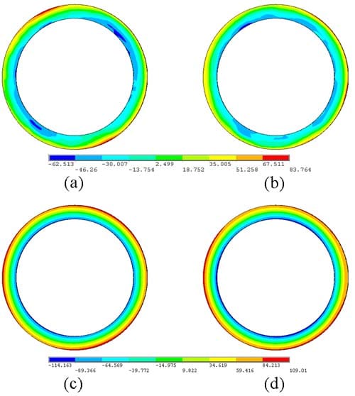
Figure C.9: Experimental results for (a) initial surface form profile, (b) clamped surface form profile, (c) machined surface form profile, (d) final surface form profile; P = 1.00 MPa, f = 0.04 mm/rev, d = 0.375 mm, S = 100 m/min
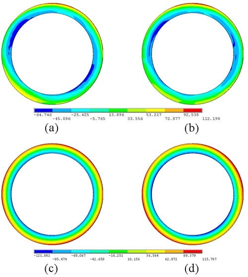
Figure C.10: Experimental results for (a) initial surface form profile, (b) clamped surface form profile, (c) machined surface form profile, (d) final surface form profile; P = 1.00 MPa, f = 0.06 mm/rev, d = 0.375 mm, S = 100 m/min
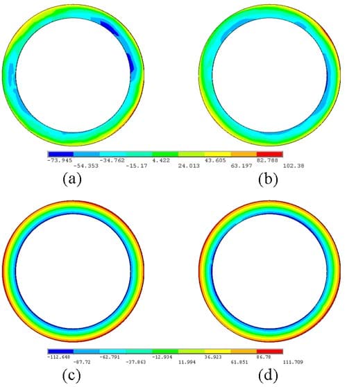
Figure C.11: Experimental results for (a) initial surface form profile, (b) clamped surface form profile, (c) machined surface form profile, (d) final surface form profile; P = 1.00 MPa, f = 0.08 mm/rev, d = 0.375 mm, S = 100 m/min
Finite Element Scripts
This appendix contains ANSYS® 11.0 APDL scripts that are representative of those used in the finite element modeling portion of this research.
!!!!!!!!!!!!!!!!!!!!!!!!!!!!!!!!!!!!!!!!!!!!!!!!!!!!!!!!!!!!
!!!!!!!!!!!!!!! IMPORT IGES FILE !!!!!!!!!!!!!!!
!!!!!!!!!!!!!!!!!!!!!!!!!!!!!!!!!!!!!!!!!!!!!!!!!!!!!!!!!!!!
/AUX15
IOPTN,IGES,NODEFEAT
IOPTN,MERGE,YES
IOPTN,SOLID,YES
IOPTN,SMALL,YES
IOPTN,GTOLER,DEFA
! DEFINE LOCAL COORDINATE SYSTEM (CYLINDRICAL)
CLOCAL,22,1,0,0,25.4
! IMPORT RING/CHUCK GEOMETRY
IGESIN,ring chuck assy1,igs
FINISH
This script was used to build and mesh the finite element model geometry:
!!!!!!!!!!!!!!!!!!!!!!!!!!!!!!!!!!!!!!!!!!!!!!!!!!!!!!!!!!!!
!!!!!!!!!!!!!!! GEOMETRY !!!!!!!!!!!!!!!
!!!!!!!!!!!!!!!!!!!!!!!!!!!!!!!!!!!!!!!!!!!!!!!!!!!!!!!!!!!!
/PREP7
! DELETE ERRANT KEYPOINT
KDELE,111
! DEFINE ELEMENT TYPES AND KEY OPTIONS
VDELE,1
ET,1,MESH200
ET,2,SOLID185
ET,3,SOLID92
KEYOPT,1,1,6
KEYOPT,1,2,0
! DEFINE MATERIAL PROPERTIES
! MAT1 = STELLITE (RING)
MP,EX,1,223000
MP,PRXY,1,0.3
! MAT2 = TOOL STEEL (JAWS)
MP,EX,2,203000
MP,PRXY,2,0.3
! DELETE MAJORITY OF RING GEOM. RECREATE BY REBUILDING FROM X-SECTION.
! THIS IS DONE TO ENABLE USE OF A MAPPED MESH FOR THE RING.
ADELE,59,86,1
LDELE,1
LDELE,3,4
LDELE,6,9
LDELE,11,12
LDELE,14,17
LDELE,19,20
LDELE,22,25
LDELE,27,31
LDELE,33,34
LDELE,36,42
LDELE,44,47
LDELE,49,53
LDELE,56
! DEFINE NEW KEYPOINTS, LINES, AREAS
KBETW,112,131,0,RATI,0.5,
KBETW,106,112,,RATI,0.5
KL,18,0.5
KL,48,0.15
KL,48,0.6
LDELE,48
L,112,4
L,4,131
L,81,69
L,1,138
L,1,4
L,5,12
L,5,112
L,8,34
L,8,92
L,8,47
L,47,85
L,47,69
L,9,34
L,9,10
L,10,12
L,9,92
L,6,106
L,10,106
L,6,112
L,12,34
L,6,12
! CREATE AREAS BY LINES
AL,1,2,7,9
AL,3,6,7,54
AL,8,9,25,28
AL,20,23,24,28
AL,17,19,20,27
AL,11,12,17,22
AL,12,14,15,35
AL,4,15,16,32
! CREATE KEYPOINTS ON JAW FACES FOR LOAD APPLICATION
!KL,182,0.5
!KL,234,0.5
!KL,130,0.5
!!!!!!!!!!!!!!!!!!!!!!!!!!!!!!!!!!!!!!!!!!!!!!!!!!!!!!!!!!!!
!!!!!!!!!!!!!!! MESHING !!!!!!!!!!!!!!!
!!!!!!!!!!!!!!!!!!!!!!!!!!!!!!!!!!!!!!!!!!!!!!!!!!!!!!!!!!!!
! DEFINE ELEMENTS RELATIVE TO CYLINDRICAL CS
ESYS,22
! SET ELEMENT SIZE CONTROLS, MESH W/ SOLID200
LESIZE,19,,,6,2
LESIZE,24,1
LESIZE,20,1
MSHAPE,0,2D
MSHKEY,1
! GRAPHICAL PICKING COMMANDS CREATED WHEN MODEL BUILT IN GUI
FLST,5,8,5,ORDE,2
FITEM,5,1
FITEM,5,-8
CM, Y,AREA
ASEL,,,,P51X
CM, Y1,AREA
AMESH, Y1
CMDELE, Y
CMDELE, Y1
CMDELE, Y2
! ROTATE MESH OF SOLID200 ELEMENTS (AREAS 1-8) 360 DEGREES
! ABOUT AXIS DEFINED BY KP 67 & 114
TYPE,2
ESIZE,,20
VROTAT,1,2,3,4,5,6,67,114,,6
VROTAT,7,8,,,,,67,114,,6
ALLSEL,ALL
!!!!!!!!!!!!!!!!!!!!!!!!!!!!!!!!!!!!!!!!!!!!!!!!!!!!!!!!!!!!
!!!!!!!!!!!!!!! JAW MESH !!!!!!!!!!!!!!!
!!!!!!!!!!!!!!!!!!!!!!!!!!!!!!!!!!!!!!!!!!!!!!!!!!!!!!!!!!!!
! FREE MESH TOP FACES WITH MESH200 FACETS, THEN EXTRUDE USING SOLID185
MAT,2
TYPE,1
VDELE,2,4,1
ASEL,S,AREA,,87,116
ASEL,U,AREA,,88,108,10
ADELE,ALL,,,1
ALLSEL,ALL
!!!!!!!!!!!!!!!!!!!!!!!!!!!!!!!!!!!!!!!!!!!!!!!!!!!!!!!!!!!!
!!!!!!!!!!!!!!! ELEMENT SIZE CTRLS !!!!!!!!!!!!!!!
!!!!!!!!!!!!!!!!!!!!!!!!!!!!!!!!!!!!!!!!!!!!!!!!!!!!!!!!!!!!
!!!!!!!!!!!!!!!!!!!!!!!!!!!!!!!!!!!!!!!!!!!!!!!!!!!!!!!!!!!!
!!!!!!!!!!!!!!! JAW 1 = VOLUME 2 !!!!!!!!!!!!!!!
!!!!!!!!!!!!!!!!!!!!!!!!!!!!!!!!!!!!!!!!!!!!!!!!!!!!!!!!!!!!
LESIZE,133,,,5
LESIZE,119,,,5
LESIZE,138,,,15
LESIZE,117,,,12
LESIZE,136,,,12
LESIZE,127,,,8
LESIZE,131,,,8
LESIZE,130,,,21
!!!!!!!!!!!!!!!!!!!!!!!!!!!!!!!!!!!!!!!!!!!!!!!!!!!!!!!!!!!! !!!!!!!!!!!!!!! JAW 2 = VOLUME 3 !!!!!!!!!!!!!!!
!!!!!!!!!!!!!!!!!!!!!!!!!!!!!!!!!!!!!!!!!!!!!!!!!!!!!!!!!!!!
LESIZE,171,,,5
LESIZE,185,,,5
LESIZE,190,,,15
LESIZE,169,,,12
LESIZE,188,,,12
LESIZE,179,,,8
LESIZE,183,,,8
LE
SIZE,182,,,21
!!!!!!!!!!!!!!!!!!!!!!!!!!!!!!!!!!!!!!!!!!!!!!!!!!!!!!!!!!!!
!!!!!!!!!!!!!!! JAW 3 = VOLUME 4 !!!!!!!!!!!!!!!
!!!!!!!!!!!!!!!!!!!!!!!!!!!!!!!!!!!!!!!!!!!!!!!!!!!!!!!!!!!!
LESIZE,237,,,5
LESIZE,223,,,5
LESIZE,242,,,15
LESIZE,221,,,12
LESIZE,240,,,12
LESIZE,235,,,8
LESIZE,231,,,8
LESIZE,234,,,21
! MESH ALL JAWS WITH MESH200 ELEMENTS
MSHAPE,0,2D
MSHKEY,0
SMRT,1
AMESH,88,108,10
! EXTRUDE MESH FOR ALL JAWS WITH SOLID185 ELEMENTS
CSYS,0
TYPE,2
MAT,2
ESIZE,,10
VEXT,88,108,10,,,15.3924
ALLSEL,ALL
CSYS,22
!!!!!!!!!!!!!!!!!!!!!!!!!!!!!!!!!!!!!!!!!!!!!!!!!!!!!!!!!!!!
!!!!!!!!!!!!!!! CONTACT ELEMENTS !!!!!!!!!!!!!!!
!!!!!!!!!!!!!!!!!!!!!!!!!!!!!!!!!!!!!!!!!!!!!!!!!!!!!!!!!!!!
MP,MU,1,0.2
MAT,1
!!!!!!!!!!!!!!!!!!!!!!!!!!!!!!!!!!!!!!!!!!!!!!!!!!!!!!!!!!!!
!!!!!!!!!!!!!!! CONTACT PAIR 1 !!!!!!!!!!!!!!!
!!!!!!!!!!!!!!!!!!!!!!!!!!!!!!!!!!!!!!!!!!!!!!!!!!!!!!!!!!!!
! DEFINE REAL CONSTANT SET
R,5
REAL,5
! DEFINE ELEMENT TYPES FOR TARGE170 & CONTA174
ET,8,170
ET,9,174
! SET ELEMENT KEY OPTIONS
KEYOPT,9,5,1
KEYOPT,9,9,0
KEYOPT,9,10,2
R,5,
RMORE,
RMORE,,0
RMORE,0
! DEFINE TARGET AREA COMPONENT
ASEL,S,,,49
ASEL,A,,,53
CM, TARGET,AREA
TYPE,8
NSLA,S,1
ESLN,S,0
ESLL,U
ESEL,U,ENAME,,188,189
! GENERATE SURFACE ELEMENTS (TARGE170) ON TARGET AREA
ESURF
ALLSEL,ALL
! DEFINE CONTACT AREA COMPONENT
ASEL,S,,,89
CM, CONTACT,AREA
TYPE,9
NSLA,S,1
ESLN,S,0
! GENERATE SURFACE ELEMENTS (CONTA174) ON CONTACT AREA
ESURF
ALLSEL
CMDEL, TARGET
CMDEL, CONTACT
!!!!!!!!!!!!!!!!!!!!!!!!!!!!!!!!!!!!!!!!!!!!!!!!!!!!!!!!!!!!
!!!!!!!!!!!!!!! CONTACT PAIR 2 !!!!!!!!!!!!!!!
!!!!!!!!!!!!!!!!!!!!!!!!!!!!!!!!!!!!!!!!!!!!!!!!!!!!!!!!!!!!
R,6
REAL,6
ET,10,170
ET,11,174
KEYOPT,11,5,1
KEYOPT,11,9,0
KEYOPT,11,10,2
R,6,
RMORE,
RMORE,,0
RMORE,0
ASEL,S,,,24
ASEL,A,,,28
CM, TARGET,AREA
TYPE,10
NSLA,S,1
ESLN,S,0
ESLL,U
ESEL,U,ENAME,,188,189
ESURF
ALLSEL,ALL
ASEL,S,,,91
CM, CONTACT,AREA
TYPE,11
NSLA,S,1
ESLN,S,0
ESURF
ALLSEL
CMDEL, TARGET
CMDEL, CONTACT
!!!!!!!!!!!!!!!!!!!!!!!!!!!!!!!!!!!!!!!!!!!!!!!!!!!!!!!!!!!!
!!!!!!!!!!!!!!! CONTACT PAIR 3 !!!!!!!!!!!!!!!
!!!!!!!!!!!!!!!!!!!!!!!!!!!!!!!!!!!!!!!!!!!!!!!!!!!!!!!!!!!!
R,7
REAL,7
ET,12,170
ET,13,174
KEYOPT,13,5,1
KEYOPT,13,9,0
KEYOPT,13,10,2
R,7,
RMORE,
RMORE,,0
RMORE,0
ASEL,S,,,24
ASEL,A,,,28
CM, TARGET,AREA
TYPE,12
NSLA,S,1
ESLN,S,0
ESLL,U
ESEL,U,ENAME,,188,189
ESURF
ALLSEL,ALL
ASEL,S,,,105
CM, CONTACT,AREA
TYPE,13
NSLA,S,1
ESLN,S,0
ESURF
ALLSEL
CMDEL, TARGET
CMDEL, CONTACT
!!!!!!!!!!!!!!!!!!!!!!!!!!!!!!!!!!!!!!!!!!!!!!!!!!!!!!!!!!!!
!!!!!!!!!!!!!!! CONTACT PAIR 4 !!!!!!!!!!!!!!!
!!!!!!!!!!!!!!!!!!!!!!!!!!!!!!!!!!!!!!!!!!!!!!!!!!!!!!!!!!!!
R,8
REAL,8
ET,14,170
ET,15,174
KEYOPT,15,5,1
KEYOPT,15,9,0
KEYOPT,15,10,2
R,8,
RMORE,
RMORE,,0
RMORE,0
ASEL,S,,,176
ASEL,A,,,179
CM, TARGET,AREA
TYPE,14
NSLA,S,1
ESLN,S,0
ESLL,U
ESEL,U,ENAME,,188,189
ESURF
ALLSEL,ALL
ASEL,S,,,99
CM, CONTACT,AREA
TYPE,15
NSLA,S,1
ESLN,S,0
ESURF
ALLSEL
CMDEL, TARGET
CMDEL, CONTACT
!!!!!!!!!!!!!!!!!!!!!!!!!!!!!!!!!!!!!!!!!!!!!!!!!!!!!!!!!!!! !!!!!!!!!!!!!!! CONTACT PAIR 5 !!!!!!!!!!!!!!! !!!!!!!!!!!!!!!!!!!!!!!!!!!!!!!!!!!!!!!!!!!!!!!!!!!!!!!!!!!!
R,9
REAL,9
ET,16,170
ET,17,174
KEYOPT,17,5,1
KEYOPT,17,9,0
KEYOPT,17,10,2
R,9,
RMORE,
RMORE,,0
RMORE,0
ASEL,S,,,154
ASEL,A,,,158
CM, TARGET,AREA
TYPE,16
NSLA,S,1
ESLN,S,0
ESLL,U
ESEL,U,ENAME,,188,189
ESURF
ALLSEL,ALL
ASEL,S,,,101
CM, CONTACT,AREA
TYPE,17
NSLA,S,1
ESLN,S,0
ESURF
ALLSEL
CMDEL, TARGET
CMDEL, CONTACT
!!!!!!!!!!!!!!!!!!!!!!!!!!!!!!!!!!!!!!!!!!!!!!!!!!!!!!!!!!!! !!!!!!!!!!!!!!! CONTACT PAIR 6 !!!!!!!!!!!!!!! !!!!!!!!!!!!!!!!!!!!!!!!!!!!!!!!!!!!!!!!!!!!!!!!!!!!!!!!!!!!
R,10
REAL,10
ET,18,170
ET,19,174
KEYOPT,19,5,1
KEYOPT,19,9,0
KEYOPT,19,10,2
R,10,
RMORE,
RMORE,,0
RMORE,0
ASEL,S,,,154
ASEL,A,,,158
CM, TARGET,AREA
TYPE,18
NSLA,S,1
ESLN,S,0
ESLL,U
ESEL,U,ENAME,,188,189
ESURF
ALLSEL,ALL
ASEL,S,,,115
CM, CONTACT,AREA
TYPE,19
NSLA,S,1
ESLN,S,0
ESURF
ALLSEL
CMDEL, TARGET
CMDEL, CONTACT
!!!!!!!!!!!!!!!!!!!!!!!!!!!!!!!!!!!!!!!!!!!!!!!!!!!!!!!!!!!! !!!!!!!!!!!!!!! CONTACT PAIR 7 !!!!!!!!!!!!!!! !!!!!!!!!!!!!!!!!!!!!!!!!!!!!!!!!!!!!!!!!!!!!!!!!!!!!!!!!!!!
R,11
REAL,11
ET,20,170
ET,21,174
KEYOPT,21,5,1
KEYOPT,21,9,0
KEYOPT,21,10,2
R,11,
RMORE,
RMORE,,0
RMORE,0
ASEL,S,,,129
ASEL,A,,,133
CM, TARGET,AREA
TYPE,20
NSLA,S,1
ESLN,S,0
ESLL,U
ESEL,U,ENAME,,188,189
ESURF
ALLSEL,ALL
ASEL,S,,,109
CM, CONTACT,AREA
TYPE,21
NSLA,S,1
ESLN,S,0
ESURF
ALLSEL
CMDEL, TARGET
CMDEL, CONTACT
!!!!!!!!!!!!!!!!!!!!!!!!!!!!!!!!!!!!!!!!!!!!!!!!!!!!!!!!!!!! !!!!!!!!!!!!!!! CONTACT PAIR 8 !!!!!!!!!!!!!!! !!!!!!!!!!!!!!!!!!!!!!!!!!!!!!!!!!!!!!!!!!!!!!!!!!!!!!!!!!!!
R,13
REAL,13
ET,24,170
ET,25,174
KEYOPT,25,5,1
KEYOPT,25,9,0
KEYOPT,25,10,2
R,13,
RMORE,
RMORE,,0
RMORE,0
ASEL,S,,,74
ASEL,A,,,78
CM, TARGET,AREA
TYPE,24
NSLA,S,1
ESLN,S,0
ESLL,U
ESEL,U,ENAME,,188,189
ESURF
ALLSEL,ALL
ASEL,S,,,111
CM, CONTACT,AREA
TYPE,25
NSLA,S,1
ESLN,S,0
ESURF
ALLSEL
CMDEL, TARGET
CMDEL, CONTACT
!!!!!!!!!!!!!!!!!!!!!!!!!!!!!!!!!!!!!!!!!!!!!!!!!!!!!!!!!!!! !!!!!!!!!!!!!!! CONTACT PAIR 9 !!!!!!!!!!!!!!! !!!!!!!!!!!!!!!!!!!!!!!!!!!!!!!!!!!!!!!!!!!!!!!!!!!!!!!!!!!!
R,14
REAL,14
ET,26,170
ET,27,174
KEYOPT,27,5,1
KEYOPT,27,9,0
KEYOPT,27,10,2
R,14,
RMORE,
RMORE,,0
RMORE,0
ASEL,S,,,74
ASEL,A,,,78
CM, TARGET,AREA
TYPE,26
NSLA,S,1
ESLN,S,0
ESLL,U
ESEL,U,ENAME,,188,189
ESURF
ALLSEL
ASEL,S,,,95
CM, CONTACT,AREA
TYPE,27
NSLA,S,1
ESLN,S,0
ESURF
ALLSEL
CMDEL, TARGET
CMDEL, CONTACT
! THERE ARE NUMEROUS DISJOINT VOLUMES THAT REPRESENT RING.
! MERGE COINCIDENT NODES TO CREATE A SINGLE RING.
ALLSEL,ALL
VSEL,S,VOLU,,1,,,0
VSEL,A,VOLU,,5,51
NSLV,S,1
NUMMRG,NODE
ALLSEL,ALL
! ALIGN NODAL COORD. SYSTEMS W/ LOCAL CYLINDRICAL, #22 (ACTIVE)
NROTAT,ALL
FINISH
This script was used to apply boundary conditions and solve for the deflections due to workholding loads:
!!!!!!!!!!!!!!!!!!!!!!!!!!!!!!!!!!!!!!!!!!!!!!!!!!!!!!!!!!!!
!!!!!!!!!!!!!!! BOUNDARY CONDITIONS !!!!!!!!!!!!!!!
!!!!!!!!!!!!!!!!!!!!!!!!!!!!!!!!!!!!!!!!!!!!!!!!!!!!!!!!!!!!
/PREP7
! SELECT JAW NODES AT LOCATION Z=0 (IN CS 22)
! CONSTRAIN NODES IN AXIAL AND TANGENTIAL DIRECTION (Z AND Y DIR)
ASEL,S,AREA,,88,108,10
NSLA,S,1
D,ALL,UY,0
D,ALL,UZ,0
! DISPLACE NODES IN RADIAL DIRECTION (X DIR)
D,ALL,UX,0.0375
ALLSEL,ALL
FINISH
/SOL
ANTYPE,0
ALLSEL,ALL
SOLVE
FINISH
This script was used to apply boundary conditions and solve for the deflections due to
machining loads:
!!!!!!!!!!!!!!!!!!!!!!!!!!!!!!!!!!!!!!!!!!!!!!!!!!!!!!!!!!!!
!!!!!!!!!!!!!!! BOUNDARY CONDITIONS !!!!!!!!!!!!!!!
!!!!!!!!!!!!!!!!!!!!!!!!!!!!!!!!!!!!!!!!!!!!!!!!!!!!!!!!!!!!
/PREP7
! SELECT JAW NODES AT LOCATION Z=0 (IN CS 22)
! CONSTRAIN NODES IN AXIAL AND TANGENTIAL DIRECTION (Z AND Y DIR)
ASEL,S,AREA,,88,108,10
NSLA,S,1
D,ALL,UY,0
D,ALL,UZ,0
! DISPLACE NODES IN RADIAL DIRECTION (X DIR)
D,ALL,UX,0.0375
ALLSEL,ALL
! SELECT RING NODES AT LOCATION Z=0 (IN CS 22)
! CONSTRAIN NODES IN ALL DIRECTIONS
ESEL,S,TYPE,,2
ESEL,R,MAT,,1
NSLE
NSEL,R,LOC,Z,0
D,ALL,UX,0
D,ALL,UY,0
D,ALL,UZ,0
ALLSEL,ALL
! DIMENSION ARRAY FOR STORAGE OF INFLUENCE COEFFICIENTS
*DIM,INFMAT,ARRAY,21,16,,,,,22
*DIM,R,ARRAY,16,,,,,,22
R(1) = 36.32
R(2) = 36.878
R(3) = 37.437
R(4) = 37.995
R(5) = 38.554
R(6) = 39.113
R(7) = 39.671
R(8) = 40.788
R(9) = 41.905
R(10) = 43.023
R(11) = 43.51
R(12) = 43.998
R(13) = 44.485
R(14) = 44.973
R(15) = 45.46
R(16) = 45.948
*DO,I,1,16
K = 1
*DO,J,90,150,3
/PREP7
ALLSEL,ALL
FDELE,ALL,ALL
NSEL,S,LOC,X,R(I)
NSEL,R,LOC,Z,15.869,16
NSEL,R,LOC,Y,J
*GET,N,NODE,,NUM,MAX
F,ALL,FZ,-1
/SOLU
ANTYPE,0
ALLSEL,ALL
SOLVE
/POST1
SET,FIRST
*VGET,infmat(K,I),NODE,N,U,Z
K=K+1
FINISH
PARSAV,ALL,parameters,txt
*ENDDO
*ENDDO
PARSAV,ALL,parameters,txt
FINISH
Pressure Film Color Chart
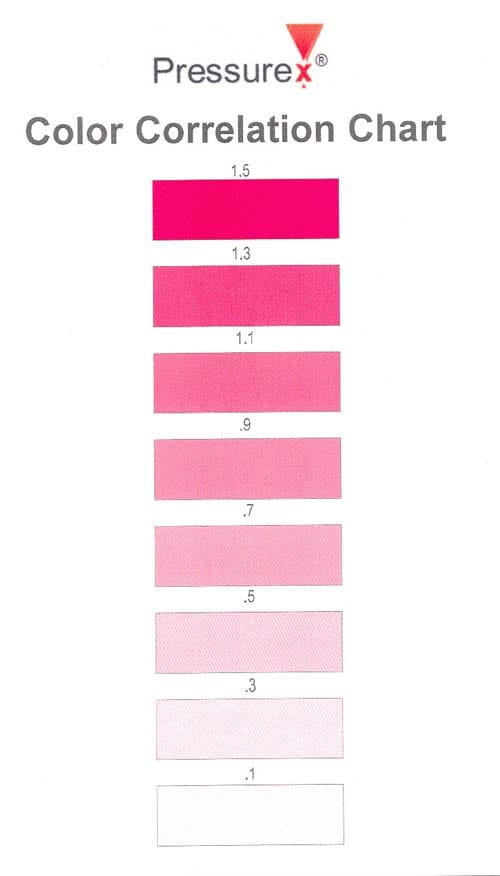
Figure E.1: Color correlation chart used to analyze Pressurex® film
References
- Matsuura Machinery PLC. https://www.matsuura.co.uk, January 2008.
- General Electric Company. https://www.ge.com, January 2008.
- S. Kalpakjian and S.R. Schmid. Manufacturing Processes for Engineering Ma- terials. Pearson Education, Inc., Upper Saddle River, NJ, 2003.
- Machinery Canada. https://www.machinerycanada.com, January 2008.
- J. Fleischer, B. Denkena, B. Winfough, and M. Mori. Workpiece and tool han- dling in metal cutting machines. Annals of the CIRP, 55(2):817{839, 2006.
- J.A. Malluck. Prediction of ring deformation due to fixturing in the turning process. Master’s thesis, Georgia Institute of Technology, 2002.
- C.B. Biezeno and R. Grammel. Engineering Dynamics, Vol. II. Blackie and Son Limited, London, 1956.
- S. Timoshenko. Theory of Elasticity. McGraw-Hill Book Company, New York, 1934.
- R.W. Bagshaw and S.T. Newman. Manufacturing data analysis of machine tool errors within a contemporary small manufacturing enterprise. International Journal of Machine Tools and Manufacture, 42(9):1065{1080, 2002.
- Y. Altintas. Manufacturing Automation: Metal Cutting Mechanics, Machine Tool Vibrations, and CNC Design. Cambridge University Press, New York, 2000.
- L. Kops, M. Gould, and M. Mizrach. Improved analysis of the workpiece in turning, based on the emerging diameter. Journal of Engineering for Industry, 115(3):253{257, 1993.
- L. Masset, J. Debongnie, S. Foreau, and T. Dumont. A model for the prediction of form errors in face milling and turning. Proceedings of the ASME Design Engineering Technical Conferences, Las Vegas, NV, Paper No. DETC99/DAC- 8692:411{417, 1999.
- Y. Kovvur, H. Ramaswarni, and S. Anand. Predictive surface generation and characterization for cylindrical turning processes. Proceedings of ASME Inter- national Mechanical Engineering Congress and Exposition, Orlando, FL, USA, 16(2):933{942, 2005.
- F. Gu, S.N. Melkote, S.G. Kapoor, and R.E. DeVor. A model for the predic- tion of surface atness in face milling. Transactions of the ASME Journal of Manufacturing Science and Engineering, 119(4):476{484, 1997.
- H. Schulz and K. Bimschas. Optimization of precision machining by simulation of the cutting process. Annals of the CIRP, 42(1):55{58, 1993.
- E. Budak. Analytical models for high performance milling. Part I: Cutting forces, structural deformations and tolerance integrity. International Journal of Machine Tools and Manufacture, 46(12{13):1478{1488, 2006.
- S. Vajpayee. The accuracy of turned surfaces. Wear, 59(2):387{396, 1980.
- R. Ramesh, M.A. Mannan, and A.N. Poo. Error compensation in machine tools – a review. part i: Geometric, cutting-force induced, and fixture-dependent errors. International Journal of Machine Tools and Manufacture, 40(9):1235{1256, 2000.
- I.M. Deiab and M.A. Elbestawi. Experimental determination of the friction coefficient on the workpiece-fixture contact surface in workholding applications. International Journal of Machine Tools and Manufacture, 45(6):705{712, 2005.
- Y. Morimoto, T. Yasui, and T. Inamura. Compensation of form deviation in nc lathe machining. Journal of the Japan Society of Precision Engineering/Seimitsu Kogaku Kaishi, 57(10):1757{1762, 1991.
- M. Rahman and Y. Ito. Machining accuracy of a cylindrical workpiece held by a three-jaw chuck. Bulletin of the Japan Society for Precision Engineering, 13(1): 7{12, 1979.
- M. F. Walter and J. E. Stahl. Machining of ring shaped workpieces. Journal of Materials Processing Technology, 48(1):239{245, 1995.
- J.A. Malluck and S.N. Melkote. Modeling of deformation of ring shaped work- pieces due to chucking and cutting forces. Journal of Manufacturing Science and Engineering, 126(1):141{147, 2004.
- M. Kurnadi, J. Morehouse, and S.N. Melkote. A workholding optimization model for turning of ring-shaped parts. International Journal of Advanced Manufac- turing Technology, 32(7{8):656{665, 2007.
- A.Y.C. Nee, A.S. Kumar, and Z.J. Tao. An intelligent fixture with a dynamic clamping scheme. Proceedings of the Institution of Mechanical Engineers, Part B: Journal of Engineering Manufacture, 214(3):183{196, 2000.
- L. Masset and J. Debongnie. Machining processes simulation: specific finite element aspects. Journal of Computational and Applied Mathematics, 168(1{2): 309{320, 2004.
- L. Nowag, J. Solter, A. Walter, and E. Brinksmeier. Effect of machining param- eters and clamping technique on residual stresses and distortion of bearing rings. Materialwissenschaft und Werkstofitechnik, 37(1):45{51, 2006.
- K.F. Eman. A new approach to form accuracy control in machining. International Journal of Production Research, 24(4):825{838, 1986.
- H. Sasahara and M. Tsutsumi. Strategic optimization of cutting conditions by model-based analysis with the aid of database utilization. Transactions of the North American Manufacturing Research Institute of SME, 32:581{588, 2004.
- E. Ozturk and E. Budak. Modeling of 5-axis milling processes. Machining Science and Technology, 11(3):287{311, 2007.
- W.A. Kline, R.E DeVor, and I.A. Shareef. Prediction of surface accuracy in end milling. Journal of Engineering for Industry, Transactions of the ASME, 104(3): 272-278, 1982.
- M. Wan, W. Zhang, K. Qiu, T. Gao, and Y. Yang. Numerical prediction of static form errors in peripheral milling of thin-walled workpieces with irregular meshes. Transactions of the ASME Journal of Manufacturing Science and Engineering, 127(1):13{22, 2005.
- G. Subramani, S.G. Kapoor, and R.E DeVor. Model for the prediction of bore cylindricity during machining. Journal of Engineering for Industry, Transactions of the ASME, 115(1):15{22, 1993.
- J. Mou. Computer-aided error modeling approach to improve the accuracy of turning processes. Computers in Industry, 24:71{80, 1994.
- Y. Yao, H. Zhao, J. Li, and Z. Yuan. Modeling of virtual workpiece with machin- ing errors representation in turning. Journal of
Materials Processing Technology, 172(3):437{444, 2006. - D.H.E. Persson, S. Jacobson, and S. Hogmark. Effect of temperature on friction and galling of laser processed Norem 02 and Stellite 21. Wear, 255:498{503, 2003.
- D.H.E. Persson, S. Jacobson, and S. Hogmark. The in uence of phase transfor- mations and oxidation on the galling resistance and low friction behaviour of a laser processed Co-based alloy. Wear, 254:1134{1140, 2003.
