

Article
Related Links
Sang-Kuy Hana, Salvatore Federicob, Marcelo Epsteina, Walter Herzogc,*
aDepartment of Mechanical and Manufacturing Engineering, The University of Calgary, 2500 University Drive NW, Calgary, Alberta T2N 1N4, Canada
bDepartment of Industrial and Mechanical Engineering, University of Catania, Viale Andrea Doria 6, Catania 95125, Italy
cHuman Performance Laboratory, Faculty of Kinesiology, The University of Calgary, 2500 University Drive NW, Calgary, Alberta T2N 1N4, Canada
Abstract
Abnormal, excessive stresses acting on articular joint surfaces are speculatedto be one of the causes for joint degeneration. However, articular surface stresses have not been studied systematically, since it is technically difficult to measure in vivo contact areas and pressures in dynamic situations. Therefore, we implemented a numerical model of articular surface contact using accurate surface geometries. The model was developed for the cat patellofemoral joint. We demonstrated that small misalignments of the patella relative to the femur change the joint contact mechanics substantially for a given external load. These results suggest that misalignment might be studied as one of the factors causing articular cartilage disorder and joint degeneration. r 2004 Elsevier Ltd. All rights reserved.
Keywords: Patellofemoral joint; Misalignment; Contact area; Contact pressure; Articular cartilage degeneration; Osteoarthritis; Continuum mechanics; Finite element modeling
1. Introduction
Articular cartilage is subjectedto a wide range of mechanical stresses associatedwi th normal, everyday joint loading in vivo, and it is known to become injured or diseased frequently in the human knee, particularly in athletes andthe elderly (Baker et al., 1985; Smillie, 1970; Lawrence et al., 1989).
Abnormal or excessive stresses acting on, or within, a joint are speculatedto be one of the causes for patellofemoral joint degeneration (Radin et al., 1978; Moskowitz, 1992). Support for this idea comes from experiments in which cartilage degeneration has been initiatedin animals by excessive loading (Dekel and Weissman, 1978; Moskowitz, 1992).
At present, the in vivo joint contact mechanics cannot be measured in diarthrodial joints during voluntary movements, although dynamic contact pressure measurements in artificial joints (e.g., Bergmann et al., 1993), and static conditions in intact diarthrodial joints have been made (e.g., Ronsky et al., 1995). Furthermore, studies performed on cartilage explants cannot explain the stress–strain states of articular cartilage subjectedto loads in the intact joint, because of the artificial boundary conditions required for in vitro testing (e.g., no interaction with the subchondral bone, andeither completely open or completely sealedlateral constraints). Also, the biological response of articular cartilage to loading performed in isolated explants in vitro, or in the intact joint, can be very different for apparently similar loading conditions (Craig, 2003; Clark et al., 2004). Therefore, theoretical approaches of accurate joint contact mechanics are urgently needed. However, exact analytical solutions can only be obtained for small displacements and two-dimensional (2-D), or axisymmetric andsim ple geometries (Athesian et al., 1994; Wu et al., 1997). When studying real joint geometries, a numerical analysis, such as the finite element (FE) method, is necessary. The purpose of this study was to combine an accurate geometrical representation of a real joint with a numerical approach of the associated contact mechanics. In order to do this, we usedthe cat patellofemoral joint for which in situ contact pressure measurements hadbeen made in the past (Clark et al., 2002). We then simulatedlateral patellar shifts of 0.5 and1.0 mm from the actual in situalignment. We hypothesizedthat these misalignments were associatedwith increasedpeak pressure, decreased contact area, higher tensile stresses at the articular surface, andhigher shear stresses at the bone–cartilage interface, for a given contact force. Such observations would be consistent with anecdotal and clinical findings of increasedpatel lofemoral degeneration with inaccurate patellar tracking.
2. Methods
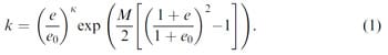
Accurate (< 20 µm) retropatellar andfemor al groove surface geometries were obtainedusing laser scanning (MicroScan Laser Profilometer, LMI Technologies, Southfield, MI, USA) (Haut et al., 1998; Couillard, 2002). The 3-D FE mesh model was created using the commercial mesh generation software, TrueGRID (Fig. 1a andb ). A large displacement contact analysis was usedwith ABAQUS 6.3. Articular cartilage was assumedto be biphasic: the solidphase was assumed linearly elastic andincompr essible, and the fluidpha se was taken as incompressible, non-viscous, andwi th a deformation-dependent permeability (Holmes and Mow, 1990). The deformation dependent permeability was described by Wu andHerzog (2000) as a function of the voidrati o e (ratio of the fluidover the solidfraction) :
 sagittal view, with the section plane on which the local contact pressure was evaluated;")
Fig. 1. Patellofemoral joint contact mesh model: (a) sagittal view, with the section plane on which the local contact pressure was evaluated; (b) frontal view, with the reference frame; and(c) contact pressure distribution for a 3N appliedload with the patella in the normal reference position, andd isplaced laterally by 0.5 and 1.0 mm.
The elastic constants andthe material parameters featuring in the expression of permeability (Eq. (1)) were taken from the literature (Wu et al., 1999; Wu and Herzog, 2000), andare shown in Table 1.

Table 1 Material properties usedin the simulations
The articular cartilage surface was assumedpe rfectly permeable, andcartilag e thickness on the femoral groove andretr opatellar surface was approximated as 0.3 and0.5 mm, respectively (Herzog et al., 1998). The articular cartilage was modeled as being attached to a cortical bone of 2.5mm thickness. In order to evaluate the effects of alignment of the patella relative to the femur, the patella was shiftedlate rally by 0.5 and 1.0mm from its reference configuration. Ramp loads from 0 to 3, 100, 150, and500 N were appliedov er a 2 s periodto the patella placedon the femoral groove.
Table 1 Material properties usedin th
e simulations
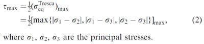
Analysis: Patellofemoral contact areas, peak pressures, andlocal pressures were calculatedand compared for the four loading conditions (ramp to 3, 100, 150, and 500 N), andthe three positions of the patella relative to the femur (normal reference position, 0.5 and1.0 mm lateral displacement of the patella relative to the femur). Contact area was defined as the area spanned by the nodes of the FE model in which contact pressure was non-zero. Peak pressure was defined as the peak pressure observedat the end of the loading ramp. Local pressures were analyzedalon g three parallel lines running from medial to lateral through the peak pressure point, and ±0.25mm distal and proximal to the peak pressure point, respectively. The maximum tensile stress was calculatedas the maximum value of the principal stresses (i.e., the three eigenvalues of the stress tensor). The maximum shear stress was calculated as half of the maximum Tresca equivalent stress:
3. Results
In the normal reference position, the patellofemoral contact area extended from the medial to the lateral side of the femoral groove, as observedexperi mentally (Clark et al., 2002). For a 0.5 and1.0 mm lateral shift of the patella from its reference position, the contact areas andpeak pressures were shifted laterally (Fig. 1c). Also, contact area decreased and peak contact pressure increasedwi th a lateral shift of the patella for all loading conditions (Fig. 2). We also calculatedthe contact pressures on the femur at the points lying on the intersection of the surface with the section plane shown in Fig. 1a, andplott edthe results with respect to the local x3 coordinate of the contact points (Fig. 1b). Comparedto the normal reference position, local loading of the laterally displaced patellar positions caused unloading medially and overloading laterally (Fig. 3).
 Normalizedpeak patellofemoral contact pressure for the four loading conditions (3, 100, 150, and 500 N) and the three positions of the patella relative to the femur (normal, 0.5 and1.0 mm lateral displacement).")
Fig. 2. (a) Normalizedpeak patellofemoral contact pressure for the four loading conditions (3, 100, 150, and 500 N) and the three positions of the patella relative to the femur (normal, 0.5 and1.0 mm lateral displacement). Normalized peak pressures increase with increasing displacement of the patella from its reference position. (b) Normalized patellofemoral contact area for the four loading conditions (3, 100, 150, and500 N) andthe three positions of the patella relative to the femur (normal, 0.5 and1.0 mm lateral displacement). Contact area increased dramatically from the 3 to 100N loading conditions, but remainedvirtually constant for further increases in loadmagnitud e. Contact area decreased with increasing patellar displacement from the reference position. The absolute values of contact pressure (in MPa) andcontact area (in mm2) are reportedfor the reference configuration.

Fig. 3. Local contact pressures along a medial–lateral line for the three positions of the patella relative to the femur for the 3N loading condition. Note, the lateral shift and increase in peak pressure with increasing lateral shifting of the patella. In this case, peak pressure from the normal reference to the 1.0mm displaced position increased by a factor of 2.
Theoretically predicted peak contact pressures were within the range of those observedexpe rimentally (Fig. 4a), while contact areas were vastly overestimatedby the numerical contact model (Fig. 4b).
 Comparison of peak contact pressure as a function of patellofemoral contact force (applied load ) calculated theoretically (Ο), andobtained experimentally (•) from cat patellofemoral joints.")
Fig. 4. (a) Comparison of peak contact pressure as a function of patellofemoral contact force (applied load ) calculated theoretically (Ο), andobtained experimentally (•) from cat patellofemoral joints. (b) Comparison of patellofemoral contact area as a function of patellofemoral contact force (applied load ) calculatedtheoretically (Ο), andobtained experimentally (•) from five cat patellofemoral joints. Theoretical contact areas were calculatedfor the whole contact area (J), andfor the whole contact minus 23.8mm2 ().
Maximal tensile stresses always occur at the articular cartilage surface, andthey remain fairly constant across different alignments of patella relative to femur. In contrast, maximal shear stresses occur near the bone– cartilage interface, andthey increase substantially with increasing misalignment of patella relative to femur (Fig. 5).
.")
Fig. 5. Maximum tensile andshear stresses for the three alignment conditions of the patella relative to the femur (normal, 0.5 and 1.0mm lateral displacement). The maximum tensile stress occurred at the articular surface andwas not greatly affected by misalignment. The maximum shear stress occurredat the bone–cartilage interface and was significantly affectedby misalignment.
4. Discussion
At present, it is impossible to determine experimentally the instantaneous, in vivo stress–strain state of articular cartilage during movement. However, there is increasing evidence that cartilage adaptation and degeneration are strongly linked to mechanical signals in the vicinity of the chondrocytes (Guilak et al., 1997). Therefore, we combinedan accurate diarthrodial joint geometry (obtained through laser digitization) with a realistic (biphasic, strain-dependent permeability) contact model of articulating joint surfaces, implemented on a commercial FE platform. We appliedphy siologically occurring patellofemoral contact forces (Hasler andHerzog , 1998) to the model to obtain the corresponding contact area and contact pressure distributions. Of course, the complete stress–strain states of the articular cartilage in the current model, or a model containing structural elements, such as chondrocytes (Wu et al., 1999; Wu andHerzog , 2000) and/or collagen fibrils, (Li et al., 1999) couldhave been determinedas well.
Comparison of the peak contact pressure data with experimental data was good, although the theoretically predicted pressures were at the lower limits of those obtainedexperimenta lly (Fig. 4a). However, this result couldbe causedby the difference in knee angles. The theoretically simulatedknee angle was 70 , whereas the experimentally obtainedresul ts correspondedto a knee angle of 100 . Furthermore, peak pressure measurements using Fuji pressure sensitive film are not trivial andmay contain errors of up to 30% associatedwith the change in contact mechanics because of insertion of the Fuji film (Wu et al., 1998), possible crinkle artifacts (Liggins, 1997), andinaccu racies with Fuji film calibration (Liggins et al., 1995).
However, comparison of the contact areas obtained theoretically andexp erimentally might be of greater concern (Fig. 4b). The theoretically predicted contact areas were always substantially greater than the experimentally measuredvalues . However, the experimental
data were obtained with Fuji pressure sensitive film. This film has a thresholdfor pressure detection, in the case at hand, of about 2.0MPa. At 3N of applied load, the predicted peak contact pressure was 0.3MPa, andthe predictedcontact area was 23.8mm2. Since the peak pressure in this case was below the Fuji film threshold, an experiment would have given a contact area of 0mm2 for the 3N loadap plication. This result indicates that the experimentally measured contact areas are likely underestimated compared to the actual contact areas. For example, if we subtract the known error at the 3N load(i.e., 23.8mm2) from all contact areas shown in Fig. 4, the correctedvalues show good agreement with the experimental values, except for the 100 and 150N load, for which the predicted values wouldstill be too high (Fig. 4b), although we suspect, this result is causedby our assumption of a constant contact area measurement error of 23.8mm2.
Summarizing, we demonstrated that small changes in patellar displacement caused changes in contact area, peak pressure, andmaxi mum shear stress near the bone–cartilage interface. However, these changes were not so dramatic that we might expect them to affect joint degeneration. Patellar misalignment also caused loaded of articular regions that were not part of the contact region in normal patellofemoral alignment (Fig. 3). We speculate that sudden loading of these normally unloaded regions might cause the problems associated with mal-tracking of the patella. This might explain the clinical observation that abnormal patellar tracking is associatedwith knee pain, and possibly, degenerative processes of the knee (Fulkerson andShea, 1990). Finally, we note that, at least for the misalignments that were studied here (lateral shift of the patella), the maximum tensile stress at the contact surface was not significantly affectedin intensity or direction.
Acknowledgements
The authors gratefully acknowledge Sylvain Couillard for providing his laser scanning experimental data, and John Wu andLeping Li for suggestions on ABAQUS modeling.
This study was partially funded by NSERC of Canada, CHIR, and the Arthritis Society of Canada.
References
- Athesian, G.A., Lai, W.M., Zhu, W.B., Mow, V.C., 1994. An asymptotic solution for the contact of two biphasic cartilage layers. Journal of Biomechanics 27, 1347–1360.
- Baker, B.E., Peckhan, A.C., Puppard, F., Sanborn, J.C., 1985. Review of meniscal injury andassociatedsports. The American Journal of Sports Medicine 13, 1–4.
- Bergmann, G., Graichen, F., Rohlmann, A., 1993. Hip joint loading during walking and running, measured in two patients. Journal of Biomechanics 26, 969–990.
- Clark, A.L., Herzog, W., Leonard, T.R., 2002. Contact area and pressure distribution in the feline patellofemoral joint under physiologically meaningful loading conditions. Journal of Biomechanics 35 (1), 53–60.
- Clark, A.L., Mills, L., Hart, D.A., Herzog, W., 2004. Muscle-induced Joint Loading Rapidly Affects Cartilage mRNA Levels in a Sitespecific Manner. Journal of Musculoskeletal Research 8 (1), 1–12.
- Couillard, S., 2002. Cartilage deformation from laser scanning. M.Sc. Thesis, University of Calgary.
- Craig, S., 2003. Effects of in-vivo joint loading on articular cartilage chondrocyte viability. M.Sc. Thesis, University of Calgary.
- Dekel, S., Weissman, S.L., 1978. Joint changes after overuse andpeak overloading of rabbit knees in vivo. Acta Orthopaedica Scandinavica 49 (6), 519–528.
- Fulkerson, J.P., Shea, K.P., 1990. Mechanical basis for patellofemoral pain and cartilage breakdown. In: Ewing, J.W. (Ed.), In Articular Cartilage andKnee Joint Function: Basic Science andArthroscopy. Raven Press, New York, pp. 93–101.
- Guilak, F., Spilker, R.L., Setton, L.A., 1997. Physical regulation of cartilage metabolism. In: Mow, V.C., Hayes, W.C. (Eds.), Basic Orthopaedic Biomechanics. Lippincott-Raven, Philadelphia, pp. 179–207.
- Hasler, E.M., Herzog, W., 1998. Quantification of in vivo patellofemoral contact forces before andafter ACL transection. Journal of Biomechanics 31 (1), 37–44.
- Haut, T.L., Hull, M.L., Howell, S.M., 1998. A high-accuracy threedimensional coordinate digitizing system for reconstructing the geometry of diarthrodial joints. Journal of Biomechanics 31 (6), 571–577.
- Herzog, W., Diet, S., Suter, E., Mayzus, P., Leonard, T.R., M. uller, C., Wu, J.Z., Epstein, M., 1998. Material andfunctio nal properties of articular cartilage andpatello femoral contact mechanics in an experimental model of osteoarthritis. Journal of Biomechanics 31, 1137–1145.
- Holmes, M.H., Mow, V.C., 1990. The non-linear characteristics of soft gels andhyd rated connective tissues in ultrafiltration. Journal of Biomechanics 23, 1145–1156.
- Lawrence, R.C., Hochberg, M.C., Kelsey, J.L., McDuffie, F.C., Medsger Jr., T.A., Felts, W.R., Shulman, L.E., 1989. Estimates of the prevalence of selectedarthritic and musculoskeletal diseases in the UnitedStates. Journal of Rheumatology 16 (4), 427–441.
- Li, L.P., Soulhat, J., Buschmann, M.D., Shirazi-Adl, A., 1999. Nonlinear analysis of cartilage in unconfinedramp compression using a fibril reinforcedporoelas tic model. Clinical Biomechanics 14, 673–682.
- Liggins, A.B., 1997. The practical application of Fuji prescale pressuresensitive film. In: Orr, J.F., Shelton, J.C. (Eds.), Optical Measurement Methods in Biomechanics. Chapman & Hall, London, pp. 173–189.
- Liggins, A.B., Hardie, W.R., Finlay, J.B., 1995. The spatial and pressure resolution of Fuji pressure-sensitive film. Experimental Mechanics 35, 166–173.
- Moskowitz, R.W., 1992. Experimental models of osteoarthrits. In: Moskowitz, R.W., Howell, D.S., Goldberg, V.M., Mankin, H.J. (Eds.), Osteoarthritis: Diagnosis and Medical/Surgical Management, 2nd Edition. W.B. Saunders, Philadelphia, pp. 233–262.
- Radin, E.L., Ehrlich, M.G., Chernack, R., 1978. Effect of repetitive impulsive loading on the knee joints of rabbits. Clinical Orthopaedics 131, 288–293.
- Ronsky, J.L., Herzog, W., Brown, T.D., Ped ersen, D.R., Grood, E.S., Butler, D.L., 1995. In-vivo quantification of the cat patellofemoral joint contact stresses andar eas. Journal of Biomechanics 28, 977–983.
- Smillie, I.S., 1970. Injuries of the Knee Joint 5th Edition. Williams &Wilkins, Baltimore.
- Wu, J.Z., Herzog, W., 2000. Finite element simulation of location- and time-dependent mechanical behavior of chondrocytes in unconfinedcompressio n tests. Annals of Biomedical Engineering 28, 318–330.
- Wu, J.Z., Herzog, W., Epstein, M., 1997. An improvedsolution for the contact of two biphasic cartilage layers. Journal of Biomechanics 30, 371–375.
- Wu, J.Z., Herzog, W., Epstein, M., 1998. Effects of inserting a pressensor film into articular joints on the actual contact mechanics. Journal of Biomechanical Engineering 120, 655–659.
- Wu, J.Z., Herzog, W., Epstein, M., 1999. Modeling of location- and time-dependent deformation of chondrocytes during cartilage loading. Journal of Biomechanics 32, 563–572.
