

Article
Related Links
By: Mark Kincart and Jeffrey Stark
SUMMARY
Predicting head gasket failure or blowout can, at best, be a difficult proposition. Many factors can contribute to head gasket failure in an engine, particularly in motorcycle and other air-cooled applications. While head gasket blowout could be blamed on improper manufacture or installation of the head gasket itself, there are other, less obvious elements which may contribute markedly to such an outcome. Testing to determine the reasons for such failure can, at times, be frustrating, time-consuming, and expensive. There does exist, however, a relatively simple methodology to assist in determining the precise relationships involved in head gasket failure. This same testing methodology is also able to point toward a relatively simple approach solution to cylinder head gasket blow outs.
INTRODUCTION
Gasket failure usually seems to be due to over-tension on the fasteners rather than from the gasket material itself. However, as we will show, thermal expansion issues, the step to stud clearance, leverage on the cylinder head as well as the quality levels of the fasteners and the method of assembly of the cylinder itself all make their own unique contribution to the overall chain of events culminating with a blown head gasket. Additionally, these same issues can create a situation where a blown gasket magnifies into valve guide wear and possible valve seat damage due to thermal load deflection. Through much trial and error and the use of a special tactile pressure sensor film (“TPSF”), it was possible to determine not only the best torque conditions for optimum yield under thermal expansion but also that the first torque value when performing the cylinder head assembly invariably sets the stage for the final torque results and thermal distortion. This usually represents over- or false tensioning of the fasteners on the head gasket assembly, creating a condition where uneven growth in the cylinder due to thermal expansion leads to catastrophic failure of the entire gasket assembly.
PROBLEM SCENARIO AND CONDITIONS
Perhaps this scenario might sound familiar: A motorcycle owner leaves the shop with a serviced motor with a new head gasket assembly. This person rides pretty hard; hits a few bars along the way; engine cools down each time. With some friends, he comes out from the bar, starts his bike so all can check out the pipes. He starts the motor cold, wicks the throttle wide open a few times, shuts the bike off and back into the bar. Now it is time to go home. All the guys get on their bikes and make a big, loud exit — hard on the throttle with cool to cold motor. This could go on for a few days, a few weeks or a few months. Several heat cycles (i.e. thermal expansions of the cylinder head), and things start to settle. All that distortion and stress need to go “somewhere”. (See Fig. 1 for an “illustration” of thermal expansion problems experienced by an over torque of a head gasket.) So, one head bolt begins to loosen; then another. Some blow-by now occurs, but only for a few minutes and then it goes away. But during the time of that blow-by, the head gasket is beating itself up on the jug and the head like a jackhammer. Now, understand, most bikes are way too loud for riders to hear that tell-tale hiss of the blow-by until it is too late. The head bolts totally lose their clamping force and a blown head gasket results. Even more disturbing, the motor is most likely cold when this happens. But, there’s more: The deflection occurring under thermal load has caused valve guide wear and possibly valve seat damage. Our rider goes to start his bike one day and now wonders why it won’t run properly or won’t run at all. He takes it back to the shop, saying; “I did not hear a thing; I have no idea how the head gasket blew.”
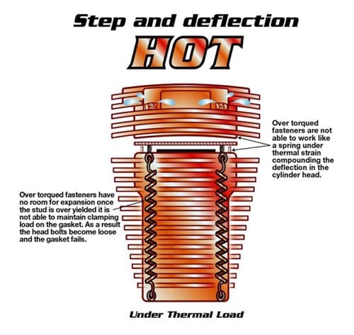
Figure 1 – An illustration of what can happen with step and deflection when there is too much tension on the fasteners, not allowing for proper thermal expansion of the gasket.
This might be humorous, but the underlying condition is quite serious. The testing process of head gasket assemblies on two different motors (A and B) revealed some very interesting differences. One might say that, from the outside, most motorcycle engines look the same: air-cooled V-Twins. On Motor A we found the cooling fins to be much thinner and more of them than on Motor B, which has very heavy cooling fins. Other differences were: Motor A uses a lead-in on the jug for the head bolts. The step in the jug on Motor B is the liner only. The distance of the step on Motor A is greater than that on Motor B. The bottom of the stud on Motor B is at a 90 degree angle, creating a potential problem area. Conversations with another colleague revealed that Company A producing Motor A claimed a 1.27 mm growth between the fins at 121.1 degrees C. Company B, with its motor, claimed around 2.03 mm growth at 121.1 degrees C. Between the two motors we also discovered the step to stud ratio to be a factor. On Motor A the step extends to within 3.56 mm of the stud; on Motor B it extends to within 4.98 mm of the stud. This appears to compound the leverage the head bolt introduces. (See Fig. 2.)
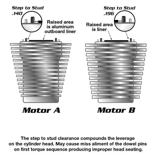
Figure 2 – Shown is the crucial “Step to Stud” ratio. Problems can occur when head bolt leverage is not taken into account when trying to properly install and torque a head gasket.
All these differences add up to thermal issues which have an effect on the growth of the cylinder. The alloys, the quality level of the fasteners themselves and assembly methods used play a major role in the overall picture. All affect the performance and design of the components and the gaskets themselves. Ideally, each engine manufacturer should have its own assembly method pertaining to that particular engine’s makeup and thermal properties.
TESTING PROCEDURES
To test the importance of step to stud ratios as pertaining to the head gaskets as well as the torque values obtaining from the fasteners themselves, it was decided to employ a specific TPSF (Ref. 1). The TPSF was used to determine flange contact area, bolt spacing and clamping force on the gasket. Several TPSF film profiles on Motors A and B were conducted using the following ranges: Low (25 – 100 kg/cm2), Medium (100 – 500 kg/cm2) and High (500 – 1300 kg/cm2). (We will hereafter refer to these film ranges as Film Low, Film Medium and Film High.) Specific gaskets used in the testing were a standard stainless steel fire ring gasket (High Per
formance Paper on Tang core) and a graphite on stainless steel tang with a modified copper fire ring (See Fig. 6). (The bottom layer of the gasket forms the fire ring and reduces cylinder head deflection.)
Initially we were unsure why the step needed to be put in the jug. At that time the step was thought to provide stability for the jug for thermal expansion and help keep the bore round. We saw it (from a sealing standpoint) as an area for high unit loading. Through our research, we determined the step is not a requirement to seal combustion. The information we now have from the film tests confidently states the step is not needed. In fact, deflection can occur with just 2.07 kg-f m of torque due to the step and starting torque value. Deflection and the level of deflection clearly will depend on whose motor is being worked on. We used Motor B using the torque sequence and values as suggested by the manufacturer. (See Fig. 2 for a step to stud issue illustration.)
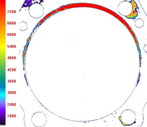
Figure 3 – Shown is the result of torque at 2.07 kg-f m meter N pattern, driver standard, only two bolts, rear cylinder, TPSF Medium. The kg/cm2 range shown here is >500 kg/cm2 with torque on only two heat bolts. A second test with torque on all four head bolts at the same conditions not only revealed >500 kg/cm2 but also significant and observable distortion in the “gasket”.
For the first test, we used Film Medium (100 – 500 kg/cm2) with a time of three minutes; N torque pattern starting on the drive side oil return port. First torque value was 2.07 kg-f m; the final torque value was 2.07 kg-f m. After installing the film and head gasket, the head was placed on the cylinder and all four head bolts were snugged using an N pattern. Torque to 2.07 kg-f m was then applied to two of the head bolts. After waiting three minutes, the head was removed. As seen in Fig. 3, the film’s 500 kg/cm2 limit was exceeded with just 2.07 kg-f m. Using another piece of film, another test was performed, using the same N pattern sequence but all four head bolts received torque to 2.07 kg-f m. We waited three minutes; then pulled the cylinder head. The film’s maximum range again was exceeded, but this time there was also observable distortion. As can be seen, one side of the gasket is now wider than the other; a gap has also occurred in the oil return area. We feel this occurred due to: 1. First torque value is too high; 2. The step to stud distance relationship compounds the leverage; 3. There is now an additional issue of proper seating of the head on the jug as the deflection can cause the two small dowel pins to cock in the head, preventing proper seating. (End result of this is some loading on fire ring due to step; this clearly indicates uneven loading on balance of the head means false torque.) As can be clearly seen, the first stage of head gasket failure is now underway, with the ultimate results as illustrated earlier with our typical bike rider.
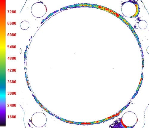
Figure 4 – With only 0.6912748 kilogram-force meter N pattern torque, not only was there a more uniform seal on the fire ring, but the maximum kg/cm2 range was >175.77 kg/cm2; this was much better than the earlier >500 kg/cm2 at 2.07 kg-f m N pattern torque.
For our second series of tests, we used Film Medium again; timed three minutes, N pattern starting on the drive side oil return port. Different this time from the earlier test was an initial and final torque value of only 0.69 kg-f m. New film and a new head gasket was installed; all four head bolts were installed with torque to 0.69 kg-f m. After waiting the three minutes and removing the film, we discovered that, with just 0.69 kg-f m of torque, over 175.77 kg/cm2 was generated. Also, we noticed a more uniform seal on the fire ring as shown in Fig. 4. This information backed up our thesis of the first torque value being crucial to proper head seating. Jumping to a higher torque on the second or third cycle can still cause deflection due to the dowels. Therefore, some caution still needs to be exercised here. Our main concern with the step lies in our observation of no support for the head past the fire ring (see Fig. 5). As the engine itself heats up, added stress is placed on the studs and the cylinder head. This also transfers, we believe, to the jug. Having the cylinder head half the thickness on one side as opposed to the other is also a concern. Clamping force on the gasket is very uneven due to the step on the cylinder.
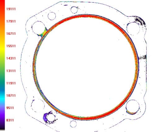
Figure 5 – While there is more uniform sealing (as shown below), there is also concern about possible improper sealing on the left side of the gasket. This could indicate deflection due to the dowels and indicate a lack of support for the head past the fire ring.
At 4.56 kg-f m, we determined that over 2,765.1 kg-f m of clamping force was generated (down to 0 kg/cm2) outside of the fire ring, depending on the density of the gasket. (See Fig. 6.) This information was gathered using a modified low density gasket and a standard supplier gasket using the supplier’s torque specifications, plus an “X” pattern gasket at 4.562 kg-f m. We decided to conduct some further testing to determine the best possible clamping values. As can be seen from Figures 7 and 8, we used Film Medium to perform an additional test with a standard gasket at 6.22 kg-f m torque. This clearly revealed no apparent change in clamping force, suggesting to us that maximum clamping force is achieved at 4.56 kg-f m or less.
CONCLUSIONS AND POSSIBLE CORRECTIONS
From our testing, we felt we could confidently suggest some possible solutions. First, since the solution for the problem of overloading/improper seating of the fasteners is a two-stage process, the step may not go away. However, we can state a great deal of the problems arise during the initial torque sequence. We suggest using an X pattern for the torque sequence, and recommend a very low value to start (between 0.69 to 1.11 kg-f m). As the torque value is increased, try to use smaller increments. Again, as was commented previously, it is the first torque value which sets the stage for the final results. Part two of the solution would be to ensure the dowel pins are clean and smooth. In fact, the more lead in on the dowel, the better. A lead in on the cylinder head would also be helpful.
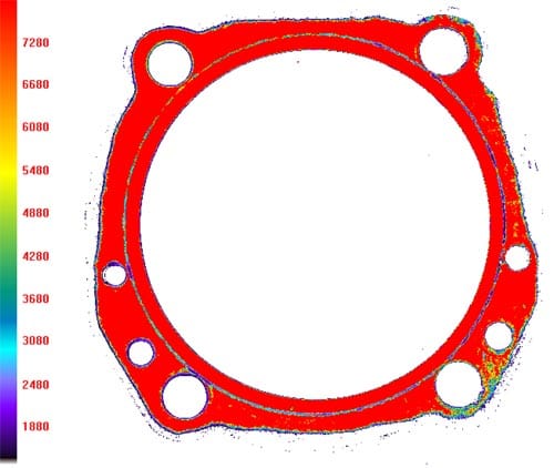
Figure 6 – In this particular test, we discovered that, at 4.56 kg-f m, over 2,765.1 kg-f m of clamping force was generated outside of the fire ring, depending on the density of the head gasket.
We would say approximately half of the false torque issues are from cocked dowels. Several of the film tests revealed this quite clearly. A possible approach would be to first fit the head without the gasket. If the cylinder head has to be rocked or tapped to get it to seat, you might not seat the head on the jug; thereby creating a false torque. The dowel should be pressed in on the jug or glued. Burs on the head also cause problems when pressing in the dowel, as it needs to go in smooth.
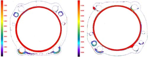
Figures 7 and 8 – In these Figures (Fig. 7, left, and Fig. 8, right), a control test at 6.22 kg-f m torque revealed no apparent change in clamping force. This suggested to us that maximum clamping force on head gaskets of air-cooled engine
s is achieved at 4.57 kg-f m or less.
As all motorcycle manufacturers use the same basic stud (9.52 mm rolled thread with a shouldered base), it is clear – based on our findings – over torque of the head bolt assembly is the prime factor in head gasket failure. Calculations showed yield on that particular fastener at 6.22 kg-f m of torque is 67% of yield. This provides, we feel, an additional 33% of yield for thermal expansion. At 5.53 kg-f m of torque we have a value of 95% yield, allowing only a 5% thermal expansion yield. This, of course, is not enough. At 95% yield the fastener will over-yield and lose its ability to function as a spring. We then start to lose our clamping force on the gasket, leading to sure destruction of the gasket and the stud.
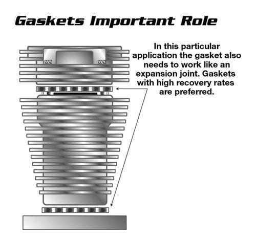
Figure 9 – Clearly seen here is the need for the head gasket(s) to provide room for expansion in the cylinder due to thermal growth. Lower torque values and lower yield values seem to allow for better thermal expansion.
All the current data and all the test imaging clearly shows the desired yield for a stud to work properly is 75% to 85% yield before thermal expansion. However, due to the amount of growth that occurs, this calls for special attention. In discussions with some other colleagues, this issue was brought up, as we were quite concerned about maintaining load with the lower torque values in a cold condition. Extensive testing with lower torque values did not produce one failure and significantly reduced piston wear and cylinder wear.
High quality fasteners are a must due to the high expansion and contraction rate of air-cooled engines. Further, clamping loads on the TPSF shows this should also work. Several supplemental tests on both Motor A and Motor B at lower torque values (as low as 4.15 kg-f m on Motor A and 6.22 kg-f m on Motor B) have also been conducted. Several test riders seem to notice a better running condition with the lower torque values. (See Figure 9 for the gasket’s important role in acting as an expansion joint.)
FINAL THOUGHTS
At this time, without extensive re-design of the cylinder head and the step/stud ratio, we feel the fix can be simple. Quality studs and head bolts installed properly with a quality thread lubricant will be the first step in a successful build. Making sure no burs or scars exist in the head pocket or on the underside of the head bolt along with properly fitted dowel pins will insure a successful seal.
We believe we have identified and possibly solved the issues surrounding head gasket failures. Clearly, as this study shows, it is easy to create a problem and not realize one has occurred. Complicating the problem is that it is not any one issue which contributes to the overall problem, i.e. head gasket failure, but a collection of issues. To the best of our knowledge, we were the first to delve into this issue at this level.
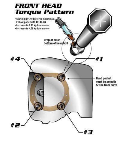
Figure 10 – In our opinion, the use of proper fasteners and a proper torque pattern will be very beneficial to avoiding head gasket failures in air-cooled engines.
The head gasket chosen will, in our opinion, have little bearing or minor influence on the total outcome. The quality of the fasteners, the proper fit of the dowel and method of assembly will determine how soon the customer comes back with a blown head gasket. In the final analysis, it all comes down to nuts and bolts.
