

Article
Related Links
M. Akagi, E. Kaneda, T. Nakamura, M. Ueno, W. Yamanashi, H. Miyajima
Kyoto University, Kyoto City, Japan
The Bisurface knee prosthesis (BP) has a posterior stabilising cam (ball-and-socket joint) in the mid-posterior region of the femorotibial joint in an attempt to improve the range of movement. Based on an in vitro weight-bearing study contact areas of the Insall/Burstein 2 (IB2) and the BP knee were compared using pressure-sensitive films. The stability afforded by the cam was evaluated by means of dislocation distances in the vertical and horizontal planes.
Significant adverse anterior translation in mid-flexion was not observed with the BP knee since the cam was effective above 60° of flexion. At flexion of 60° or more, the total contact areas were larger, as the cam represented a weight-bearing surface. The dislocation distances for the BP knee compared favourably with those for the IB2 knee. We conclude that the cam of the BP knee allows good movement, stability and wear.
Mid- and long-term follow-up studies of posterior stabilising knee prostheses have shown good function, movement and survivorship.1-5 In vivo kinematic analyses have demonstrated that the femoral component rolls posteriorly during flexion, as in normal knees.6 The Insall/Burstein (IB) prosthesis is the best example of the posterior stabilised design, and has been used worldwide for more than 20 years. Some disadvantages, however, have been reported such as the large piece of intercondylar bone which has to be removed to allow for the femoral cam,7 posterior dislocation of the cam,8,9 the patellar-clunk syndrome,10 and wear of the polyethylene surface of the tibial post.11
In collaboration with Kyocera Corporation (Kyoto, Japan) we have developed a new posterior stabilising knee called the Bisurface (BP) prosthesis. This has a ball-andsocket joint in the mid-posterior region of the femorotibial joint which is an inversion of the cam mechanism used in the conventional posterior stabilising prosthesis (Fig. 1). This mechanism is designed to allow femoral rollback, to extend the range of movement and to improve posterior stabilisation and weight-bearing. The posterior condylar surfaces of the tibial insert are relatively flattened to allow extensive rollback and axial rotation in flexion. The cam mechanism does not require extra bone to be removed from the femur and therefore the patellar clunk syndrome cannot develop. The prosthesis has been in clinical use since 1989.12
Our aim was to determine if the BP knee has achieved its design objectives, namely a good balance between movement, stability and wear. We have therefore compared its contact surface with that of the IB2 knee in vivo and analysed the stability of the cam mechanism by means of dislocation distances.
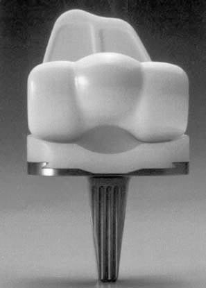
Fig 1 – Photograph of the posterior view of the BP knee prosthesis (type 3 plus). Note the balland socket joint in the mid-posterior portion of the femoral and tibial component.
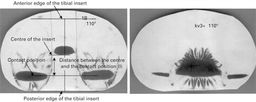
Fig 2 – The impressions on the pressure-sensitive film (ultrasuper low scale) at 110° of flexion for a) the IB2 knee and b) the BP knee.
Patients and Methods
In vivo contact position study. We determined femorotibial contact positions under weight-bearing conditions in the mid-sagittal plane in vivo in ten well-functioning knees, five BP and five IB2, using lateral fluoroscopic images (Digitalradiography DR-2000MC; Hitachi Medical Corporation, Tokyo, Japan). The mean Hospital for Special Surgery knee score was 92.4 points and the mean age at operation 58 years in the BP group and 90.7 points and 61 years in the IB2 group. The images for each patient were recorded one year after operation.
Under fluoroscopy, the tibial component was positioned accurately for a lateral view. The leg was fixed to a holder so that the knee was maintained in the centre of the fluoroscopic range. Five successive movements of the knee while climbing a 30 cm step were recorded on videotape which was digitised to a personal computer. From the images produced at a rate of 30 Hz by fluoroscopy, still images at 30° intervals from 0° to 90° of flexion were selected using video-editing software (Adobe After Effects V4.02, Adobe Systems Inc, San Jose, California). Then, according to the method of Stiehl et al,13 the relative positions of the components in the sagittal plane were determined using the still images.
For the loading tests we used the small IB2 prosthesis with a 12 mm tibial polyethylene insert and an anteroposterior width of the tibial insert and the femoral component of 42 and 59 mm, respectively, and the standard BP with a 11 mm insert and an anteroposterior width of the tibal insert and the femoral component of 43 and 58 mm. These were chosen because their size and thickness of the polyethylene matched best. The contact positions of the femorotibial joint at each angle of flexion were investigated using ultrasuper low-scale pressure-sensitive films (Fuji Prescale; Fuji Film Corporation, Tokyo, Japan). After mounting the components in a servohydraulic test machine (Model HES-S-4; Marutani-shiko Inc, Fukuoka, Japan) according to the mean in vivo position of the components, a 300 kg force was applied to the surface of the joint with the film placed between the components. The contact positions of ten knees at each angle of flexion were recorded as the centres of the impressions in the condylar regions.
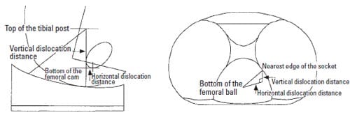
Fig 3 – Diagram showing the measurement of the vertical and horizontal dislocation distances for a) the IB2 and b) the BP knees.
The distance between the centre of the tibial insert and the contact position was measured on the film using imageanalysing software (NIH Image V1.61; National Institute of Health, Bethesda, Maryland) as shown in Figure 2. Assuming that the posterior stabilising cam should engage during flexion of more than 90°, the contact positions were determined at 110° and 130° of flexion.
Contact area study based on in vivo positional data. Measurements of the contact area of the articulating surface were carried out at room temperature (24°C) using ultrasuper low-scale films. With the components in the test machine mounted according to the positional data in vivo, a 300 kg force was applied to the surface of the joint at each angle of flexion with the film placed between the components. In all tests, the loading conditions followed the protocol recommended by the manufacturer, i.e., five seconds to obtain the peak load, five seconds to maintain the load and five seconds to remove the load and produce the impression. When the tests were done on the IB2 knee, the mid-anterior portion of the film was prepared in order to make a surface which covered the posterior aspect of the tibial post. The loading tests at each angle of flexion were repeated five times using five different tibial polyethylene inserts in both the IB2 and BP knees. Using the image analysis method described by Heim, Postak and Greenwald,14 Szivek, Cutignola and Volz,15 and Szivek, Anderson and Benjamin16 total contact areas were measured at each angle of flexion. Since the tests at over 90° of flexion gave three impressions (two in the medial and lateral condylar regions and one in the region of the cam), they were analysed separately in the condylar and the cam regions (Fig. 2). Coloured areas around the impression of the ball-and-socket joint, which were attributed to wrinkles in the film, were removed so that the contact areas were not overestimated.
Dislocation distance study. The vertical and horizontal dislocation distances of the IB2 knee were assessed at 5° intervals from 60° to 130° of flexion. According to Delp et al8 and Kocmond et al9 the vertical dislocation distance was defined as the vertical distance from the top of the tibial post to the bottom of the femoral cam. The horizontal dislocation distance was defined as the horizontal distance between these two points (Fig. 3a). The dislocation distance of the BP knee was defined as the minimal distance from the bottom of the femoral ball to the edge of the socket. This distance was calculated at 5° intervals from 60° to 130° of flexion using the three-dimensional models of the BP components and computer-assisted design software (EMS; Unigraphics Solution Inc, St Louis, Missouri) on a workstation computer (Sun Microsystems Inc, San Francisco, California). The vertical and horizontal dislocation distances were defined as the vertical and horizontal components of the spatial dislocation distance, respectively (Fig. 3b).
Results
In vivo contact position study. In the IB2 knee the impressions on the pressure-sensitive films showed that the contact position at 0° of flexion was located 1.3 ± 1.9 mm anterior to the centre of the tibial insert in the sagittal plane. Although the femur translated posteriorly up to approximately 16 mm through the range of movement, an adverse anterior translation was observed from 30° to 60° of flexion (Fig. 4). The magnitude of this translation was 3.2 mm (p = 0.0045, 95% confidence interval 1.67 to 4.77). In the BP knee, the femorotibial contact position started 3.8 ± 1.2 mm posterior to the centre of the tibial insert (Fig. 4). The femur translated posteriorly up to approximately 10 mm throughout the range of movement. Significant adverse anterior translation of the femur was not observed between 30° and 60° of flexion (p = 0.33). The contact position of the BP knee at 0° of flexion was significantly more posterior than that of the IB2 knee (p = 0.0096). At 60° and 90° of flexion, the contact position of the BP knee was also significantly more posterior than that of the IB2 knee (p = 0.002 at 60° of flexion; p = 0.004 at 90° of flexion).
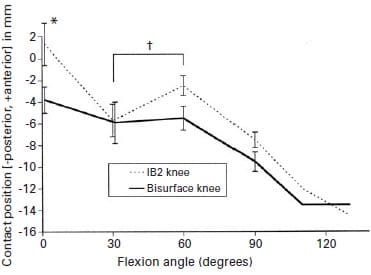
Fig 4 – Graph showing the changes in the femorotibial contact positions of the IB2 and BP knees in the sagittal plane. The positions at 110° and 130° of flexion were measured assuming that the posterior stabilising cam had already become engaged. Error bars give the standard deviation (*p < 0.01, †p < 0.005).
Contact area study based on in vivo positional data. As shown in Table I the total contact areas of the BP knee were significantly larger than those for the IB2 knee at flexion of 60° or more (p < 0.00001). There was no significant differences at 0° and 30° (p = 0.19 and 0.28, respectively). The cam of the IB2 knee did not engage until 90° of flexion, while that of the BP knee engaged from 60° of flexion onwards. Throughout the range, the major bearing surface of the IB2 knee was the condylar region, while that of the BP changed from the condylar region to the cam region at 90° of flexion (Fig. 5).
The horizontal dislocation distance for the IB2 knee was small and less than 4 mm for over 90° of flexion. In the BP knee, it was almost constant and greater than 13.5 mm for more than 90° of flexion (Fig. 6).
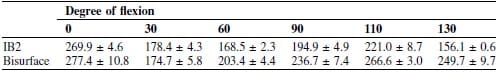
Table I. The mean ± SD total contact areas (mm2) of the five IB2 knees and the five Bisurface knees
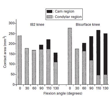
Fig 5 – Contact area of the IB2 and BP knees according to the angle of flexion. The overall bar height depicts the total contact area. The contact area in the cam region is shown in black.
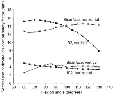
Fig 6 – The vertical and horizontal dislocation distances of the IB2 and BP knees according to angle of flexion.
Discussion
The IB knee was introduced in 1978 as a modification of the total condylar prosthesis.1 It was designed specifically to improve the range of movement and to give additional stability. We introduced the BP knee 11 years later, in an attempt to achieve further improvement in the range of flexion of the knee without affecting the survival of the prosthesis. The large femoral rollback provided by the balland- socket joint allows maximum flexion of 140°. Midterm follow-up showed that over 70% of knees had flexion of more than 120°, and there were no revisions because of failure of the tibial polyethylene insert.12 It was not clear, however, whether the excellent range of movement which was achieved would affect the long-term survival of the prosthesis.17 Furthermore, it was uncertain from what angle of flexion the cam could be effective as a posterior stabiliser and a weight-bearing surface in vivo. Assessment of the stability afforded by the cam was also necessary as two of 223 knees had recurrent mediolateral dislocation.12
A study of the contact position in vivo revealed that in the IB2 knee at 0° of flexion it was located slightly anterior to the centre of the tibial insert in the sagittal plane whereas in the BP knee the femorotibial contact position began posterior to the centre of the tibial insert. The contact position of the IB2 knee is more physiological than that of the BP knee.13 The IB2 knee has an anterior uplift of the tibial articular surface which allows contact more anteriorly compared with the BP knee. The significant adverse anterior translation in mid-flexion was not observed with the BP knee. The cam of the BP knee prevents anterior translation of the femur because it is effective above 60° of flexion.
In the IB2 knee, the major bearing surface was the condylar region throughout the range of movement, maintaining a contact of over 100 mm2 in deep flexion, which is attributable to close conformity of the tibial insert in the anteroposterior plane. In the BP knee, the contact area of the condylar region decreased to less than 50 mm2 as the angle of flexion increased, because of the posterior flat surface of the tibial insert in the anteroposterior plane. The total contact area increased at flexion of 60° or more because the cam was a weight-bearing surface. The major bearing surface moved from the condylar region to the cam region at 90° of flexion (Fig. 5). The low contact pressure which resulted from the large total contact area has the advantage of reducing deformation of the polyethylene, which may cause less wear.18
In our study, the stability of the cam mechanism in the IB2 and BP knees was assessed using two parameters of dislocation, the vertical and horizontal dislocation distances. The vertical dislocation distance for the IB2 knee showed a convex curve with a peak of 15.5 mm at 70° of flexion and decreased with flexion to 7.9 mm at 130°, which is consistent with the results of Kocmond et al.9 The distance for the BP knee was smaller than that for the IB2 knee throughout the same range, but the horizontal dislocation distance of the BP knee was greater throughout the range of movement and did not decrease with flexion (Fig. 6). In the IB2 knee, posterior dislocation of the cam may occur whereas in the BP knee, mediolateral dislocation of the cam has been reported.12 Since the direction of the dislocation is different between these prostheses, the movements causing the dislocation cannot be compared. It may be an advantage of the cam mechanism in the BP knee that the risk of the dislocation does not increase with flexion of the knee. Good balance of the medial and lateral collateral ligaments is required to avoid dislocation of the cam of the BP knee, because of the shallow ball-and-socket and posterior tibial condylar surfaces.
One weakness of the study may be that positional data in vivo were collected from a two-dimensional analysis, in which the axial rotation of the knee was not considered. Contact area and stress studies based on three-dimensional positional data are required. We believe that the results presented here provide valuable information on the cam mechanism of the BP knee, as the measurements were made in comparison with the IB2 knee, the survivorship of which has been established in many studies.1-3
In summary, we believe that the cam of the BP knee is a promising aspect which provides a good balance between movement, stability and wear.
References
- Insall JN, Lachiewicz PF, Burstein AH. The posterior stabilized condylar prosthesis: a modification of the total condylar design: two to four-year clinical experience. J Bone Joint Surg [Am] 1982;64-A:1317-23.
- Scott WN, Rubinstein M, Scuderi G. Results after knee replacement with a posterior cruciate-substituting prosthesis. J Bone Joint Surg [Am] 1988;70-A:1163-73.
- Stern SH, Insall JN. Posterior stabilized prosthesis: results after follow-up of nine to twelve years. J Bone Joint Surg [Am] 1992;74-A:980-6.
- Maloney WJ, Schurman DJ. The effects of implant design on range of motion after total knee arthroplasty. Clin Orthop 1992;278:147-52.
- Ranawat CS, Luessenhop CP, Rodriguez JA. The pressfit condylar modular total knee system: four-to-six year results with a posteriorcruciate- substituting design. J Bone Joint Surg [Am] 1997;79-A:342- 8
- Dennis DA, Komistek RD, Hoff WA, Gabriel SM. In vivo knee kinematics derived using an inverse perspective technique. Clin Orthop 1996;331:107-17.
- Vince KG. Principles of condylar knee arthroplasty: issues evolving. Instr Course Lect 1993;42:315-24.
- Delp SL, Kocmond JH, Stern SH. Tradeoffs between motion and stability in posterior substituting knee arthroplasty design. J Biomech 1995;28:1155-66.
- Kocmond JH, Delp SL, Stern SH. Stability and range of motion of Insall-Burstein condylar prostheses: a computer simulation study. J Arthroplasty 1995;10:383-8.
- Hozack WJ, Rothman RH, Booth RE Jr, Balderston RA. The patellar clunk syndrome: a complication of posterior stabilized total knee arthroplasty. Clin Orthop 1989;241:203-8.
- Puloski S, McCalden R, MacDonald S, Bourne R, Rorabeck C. Post wear in posterior stabilized TKA: an unrecognised source of polyethylene debris. Trans ORS 2000;25:444.
- Akagi M, Nakamura T, Matsusue Y, et al. The Bisurface total knee replacement: a unique design for flexion: four-to-nine-year follow-up study. J Bone Joint Surg [Am] 2000;82-A:1626-33.
- Stiehl JB, Komistek RD, Dennis DA, Paxon RD, Hoff WA. Fluoroscopic analysis of kinematics after posterior-cruciate-retaining knee arthroplasty. J Bone Joint Surg [Br] 1995;77-B:884-9.
Heim CS, Postak PD, Greenwald AS. Factors influencing the longevity of UHMWPE tibial components. Instr Course Lect 1996;45:303-12. - Szivek JA, Cutignola AM, Volz RG. Tibiofemoral contact stress and stress distribution evaluation of total knee arthroplasties. J Arthroplasty 1995;10:480-91.
- Szivek JA, Anderson PL, Benjamin JB. Average and peak contact stress distribution evaluation of total knee arthroplasties. J Arthroplasty 1996;11:952-63.
- Soudry M, Walker PS, Reilly DT, Kurosawa H, Sledge CB. Effects of total knee replacement design on femoral-tibial contact conditions. J Arthroplasty 1986;1:35-45.
- Wright TM, Fukubayashi T, Burstein AH. The effect of carbon fiber reinforcement on contact area, contact pressure, and time-dependent deformation in polyethylene tibial components. J Biomed Mater Res 1981;15:719-30.
![]()