


Article
Related Links
Article: PLUS Journal – English
By Jeffrey G. Stark, President, Sensor Products Inc., and Karl H. Dietz
When laminating dry film photo resist there is the potential danger of wrinkle formation due to uneven pressure between the lamination rolls. The pressure gauge reading on the laminator is of limited informational value. The actual pressure profile across the width of a copper-clad laminate in the nip between straight or crowned lamination rolls can be measured by the use of a pressure indicating film. The results of such a measurement can lead to significantly improved dry film resist lamination yields.
In lamination of a printed circuit board, we are trying to achieve good contact between the resist and the substrate surface by making the resist flow to conform to the surface topography. Flow is achieved by lowering the resist viscosity through heat, and by applying a pressure differential for a certain time to cause the flow. The pressure may be transmitted to the lamination rolls pneumatically, hydraulically, mechanically, or a combination of these means.
Insufficient pressure and/or non-uniform pressure can lead to lamination defects such as dry film resist wrinkles or open defects in print and etch due to poor resist conformation caused by insufficient nip pressure [1-9]. So it is desirable to have a way of measuring nip pressure magnitude and uniformity. Pressurex® [10] surface pressure indicating film measures the actual force profile at the interface of the roller set. The pressure indicating film is placed between the two rolls before closing the nip. After closing the nip, and applying the pressure, you can then observe the image captured by the pressure indicating film revealing both the pressure distribution and magnitude (footprint as it is commonly called).
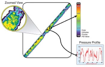
Fig. 1: Pressurex® Film Reveals the Nip Roller Pressure Profile in the Lamination Press
Measurement and Effects of Lamination Pressure Uniformity
Pressurex® measures pressure from 2 to 43,200 PSI (0.14 – 3,000 kg/cm²). When placed between contacting surfaces, it instantaneously and permanently changes color directly proportional to the actual pressure applied (Fig. 2). The precise pressure magnitude is easily determined by comparing color variation results to a color correlation chart (conceptually similar to interpreting Litmus paper).
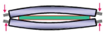
Fig. 2: Illustration of Roll Bending (Exaggerated)
When performing the process of dry film lamination upon a composite structure or photopolymer and polyester film to a metal-clad dielectric the possibility of the photoresist wrinkling or bubbling often exists. By carefully monitoring both pressure magnitude and distribution within your lamination rollers with pressure indicating films, wrinkling induced defects can be reduced significantly. Over tightened or loose or worn roll chucks can cause roller misalignments and imperfect nips – both of which are the primary contributors to intermittent wrinkling.
The force on the resist is not measured directly. A pressure gauge measures pressure applied to the pneumatic cylinders which close the lamination rolls. The actual force on the resist depends on the design of the roll loading system, taking into account the actual area of the cylinders and the mechanical leverage, if any, of the system. Since the force is applied to the resist through an elastomeric roll covering, it is distributed as pressure (force per unit area) which is dependent on the width of the board, and the width of the roll nip’s footprint is influenced by the total force applied, the roll diameter, and the thickness and durometer of the roll covering. The pressure across the footprint varies from zero at the edges to some peak pressure at the center of the nip where the roll covering is compressed the greatest. The average of this pressure profile (roughly described by a parabola) is about 2/3 of the peak pressure. When referring to nip pressure, we are usually discussing this average pressure instead of peak pressure, because it is simpler to determine. To keep things simple, however, we will talk about nip forces in terms of force per unit length of board width (pounds per inch or kilograms per centimeter), ignoring the actual width of the footprint.
This test can also be conducted while a resist covered copper-clad laminate is inserted between the rolls. This test gives insight into a potential problem with bowing of rolls, especially with thicker boards, and the test can measure the effectiveness of so called crowned rolls [2] in counteracting bowing and in achieving a uniform pressure profile across the panel (see discussion below). Roll bending is illustrated in Figure 2.
Whether roll bending is negligible or whether it is a significant factor that affects lamination quality depends on a variety of parameters. Hot roll laminators that work at relatively low loads and feature large diameter rolls are less prone to roll bending. Roll bending affects outerlayer lamination more than innerlayer lamination because the thickness of the multilayer boards is great enough to allow roll bending. Thin boards or panels permit the rolls to touch on either side of the panel, reducing the tendency to bend. The model suggests that the thickness of the dielectric core, plus copper, plus resist thickness must be greater than 22 mils (550 micron) before roll bending defects are noticed. When roll bending occurs, the center of the panel is laminated at a lower pressure than the edges, and a higher abundance of open and dish-down defects will be noted in a print and etch application along the center of the panel in machine direction.
To measure improved resist conformation at higher pressures we used AOI to test for circuitry defects which are associated with poor resist conformation, such as opens, nicks, dish-downs, and line thinning on a print and etch test pattern, at air pressures of 4 Bars and 7 Bars with an ASL-24 automatic sheet laminator (Tab. 1). The two pressures correspond to forces of 36 lbs/in and 62 lbs/in, respectively. At the higher pressure, defects were reduced 79% from the lower pressure level. While this is a significant reduction, it is difficult to take advantage of the higher pressure because the lamination rolls bend under the increased pressure.
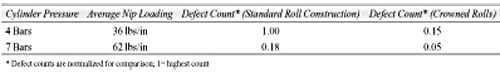
Tab. 1: Effect of Roll Pressure and Profile on Conformation Related Defects
This roll bending results in an uneven roll footprint on the resist: the footprint is narrow at the center of the rolls and wider at the ends. This means that the pressure on the resist at the center is less than at the ends. Laminator suppliers are aware of this phenomenon and try to build the rolls as sturdy as is practical. Residual roll bending can be compensated for with rolls which are crowned [2]. A crowned roll has a rubber covering which is thicker in the center than at the edges and changes gradually from center to edge, resulting in a curved profile. In this case we found that the correct amount of crown for the ASL-24 was in the range of 3 to 4 mils (75 to 100 microns). Figures 3 and 4 illustrate footprints caused by a bending straight roll and that of a crowned roll.
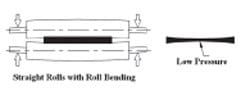
Fig. 3: Nip Pressure Profile with Straight Rolls
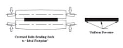
Fig. 4: Nip Pressure Profile with Crowned Rolls
Table 1 shows how crowning reduces the circuitry defect count both in the low and high pressure modes, the best case being high pressure and crowned rolls. Rubber suppliers such as Robinson Rubber and Abba Rubber International, Inc. are able to supply such crowned rolls.
Figure 5 maps the open defects for different pressures and roll profiles. The beneficial effect of higher pressure is evident. Also, for straight rolls that are bending, one can see the high abundance of opens in the center of the board in machine direction where the pressure is lowest due to roll bending.
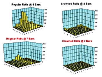
Fig. 5: Open Circuit Defects as a Function of Pressure and Roll Profile
With regard to maximizing the applied nip loading, the equipment design is the limiting factor. The strength of the rolls and the roll-loading mechanism usually limit the load, although available air pressure can be a constraint at some locations. The available force can be concentrated in a very narrow footprint by reducing roll diameter and the thickness of the roll covering, but this aggravates the roll strength and bending issue.
Lamination wrinkles
It should be noted that a properly aligned and maintained laminator is the first step towards wrinkle-free lamination (Fig. 6). Figure 7 shows lamination wrinkles pointing in one direction. Likely causes are rolls closing on right side before left side, or the closing force is greater on the right hand side.
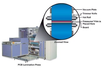
Fig. 6: Properly Aligned Laminator
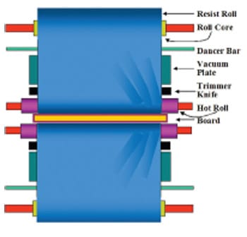
Fig. 7: Lamination Wrinkles (Possible Causes: Lamination Rolls Closing on Right Side Before Left Side; Closing Force Greater on the Right Side)
A general rule is that wrinkles, on a reasonably maintained laminator, are a problem only when laminating wide (>510 mm; >20”) resist or when laminating very thin (< 0.2 mm; <0.008”) laminate.
Roll bending
Laminator rolls bend when subjected to lamination loading. The bending causes higher driving speeds at the edges than in the center of the panel. While it usually does not affect the panels, except for very thin laminate, it can drive the resist film in a way that the film edges tend to move toward the middle, resulting in lamination wrinkles. If the loading is high enough to iron out the wrinkles during the time the film is being held by the vacuum bar, the wrinkles may not appear until the very end of the cut sheet when the film is dropped by the vacuum bar. At this point there is no restraint of the trailing edge and the last inch or so is likely to gather and wrinkle. Frequently, comet tails on tooling holes are caused by a combination of roll bending and poor control of the resist trailing edge.
Uneven air cylinder pressures
The clamp pressures (these are the air cylinders closing the rolls) must be set at the same pressure for wrinkle-free lamination. This source may be one of the biggest causes of long wrinkles starting mostly at the middle of the panel and moving back at a small angle to the lamination direction. The gauges are not always reliable indicators for the actual pressure. A periodic independent pressure check is advisable.
Post-lamination wrinkles
The post-lamination wrinkles appear after lamination and run in machine direction (Fig. 8). The post-lamination wrinkles can have a variety of causes one of which can be excessive lamination pressure. Post-lamination wrinkles are caused by heat and stress in the polyester base. While the need for good conformation requires as high a lamination pressure as possible, this pressure can add to the stress in the base. It would be better to use two nips set at medium pressures and temperatures than one nip at high pressure and high temperature if post-lamination wrinkles are a problem. The second nip should be directly after the first one to minimize heat loss between nips. Note that this arrangement would be more useful on multilayer panels than on innerlayers.
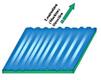
Fig. 8: Post-Lamination Wrinkles (Exaggerated)
Result
In conclusion, maintaining the correct and uniform pressure across a hot roll laminator nip, e.g. through the use of pressure sensitive indicator film, is a useful process quality assurance technique for the detection and correction of roll misalignment, too low, or excessive or uneven pressure which can lead to poor resist conformation and/or dry film lamination wrinkles which in turn will lead to yield losses.
References
- Edward Hagan: The Role of Dry-Film Lamination in the Making of Ultra-Fine Pitch PC Boards, Technical Paper S12-4, Proceedings, Printed Circuits Expo ’98, Long Beach, CA, April 26-30, 1998
- E. F. Hagan: Using Crowned Rolls to Compensate for Roll Bending, Technical Bulletin TB-9739 Rev. 1.0 (7/97), DuPont Photopolymer & Electronic Materials
- Edward F. Hagan: Effects of Lamination Parameters on Dry Film Photoresist Conformation, Technical Paper F9, Proceedings, IPC Works ‘96, October 19-25, 1996, Naples, FL
- Karl H. Dietz: Fine Lines in High Yields, (Part XXVIII): Advances in Hot Roll Lamination of Dry Film Photoresist (Part A), CircuiTree Magazine, December 1997, pg. 60
- Karl H. Dietz: Fine Lines in High Yields, (Part XXIX): Advances in Hot Roll Lamination of Dry Film Photoresist (Part B), CircuiTree Magazine, January 1998, pg. 18
- E. Hagan, K. Dietz: Dry Film Lamination Process Effects of Lamination Parameters on Wrinkling and Dimensional Properties of Dry Film and Copper-Clad Laminate, Technical PaperFilm S05-2, Proceedings, IPC Printed Circuit Expo ’99, March 14-18, 1999, Long Beach, CA
- Karl. H. Dietz, Edward F. Hagan: The Process of Dry Film Lamination (Part I), PC Fab, September 1999, Vol. 22, No. 9, pg. 42
- Karl. H. Dietz, Edward F. Hagan: The Process of Dry Film Lamination (PartII), PC Fab, October 1999, Vol. 22, No. 10, pg. 38
- Karl H. Dietz: Fine Lines in High Yields, (Part CXXXV): The Effects of Lamination Roll Mechanics on Conformation, CircuiTree Magazine, December 2006, pg. 64
- Pressurex® Measurement System, Sensor Products Inc., 300 Madison Avenue, Madison, NJ 07940, USA (https://www.sensorprod.com/pcb)