


Article: The Fabricator
The traditional method of measuring pressure distribution in stamping operations— the die spotting blue technique— indicates the pressure points but not how much pressure. This makes it difficult to determine if all the pressures the various die components are exerting are balanced. Although knowledgeable plant personnel are needed to make fine adjustments repeatedly on the press for ongoing production, the initial die build and balancing are vital for positive long-term results.
The restrike station often exerts a concentrated force near the exit side of the die, particularly on thick or formed materials. Unbalanced pressures can cause the die to "kick," resulting in premature fatigue, excess wear, and cracking or breakage of die components.
A thin, flexible, Mylar-based sensor film that instantly captures and permanently records pressure distribution and magnitude between any two mating or contacting surfaces has emerged as an alternative to traditional pressure testing. The best way to achieve optimal balance throughout the die is by paying close attention to pressure readings from the film and making adjustments in the gutting station area, usually by varying the stripper pressures when balancing infeed to output die ends.
How It Works
The film was tested at Five Star Tooling, a manufacturer of progressive dies in Aurora, Ont. The setup was a 400-ton, 5-foot-long progressive die used to stamp an arched structural car component from 0.080-inch-thick steel coil (see Figure 1).
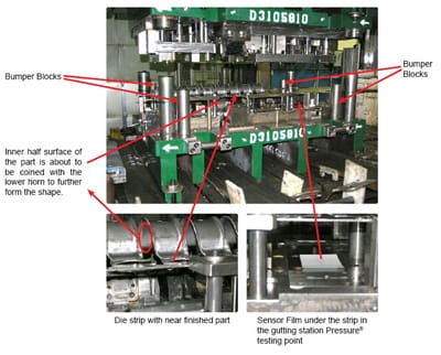
Figure 1: The 400-ton pressure testing setup shows the die
components and bumper blocks.
During testing, the film was used to analyze the pressure on and around the cutting edges of the progressive-die assembly. Figure 2 shows that when the press and upper die gutting punches move down, they contact the material strip shortly after the stripper clamps the material in place. Further downward motion causes the compressive forces to act on the microcapsules of the sensor film just before cutting through the strip and film. This pressure causes the sensor film’s microcapsules to burst, producing an instantaneous and permanent, high-resolution topographical image of pressure variation across the contact area. After one full press stroke, the film is removed and examined.
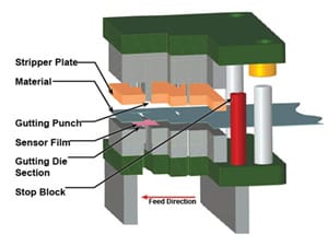
Figure 2: The sensor film is placed in the progressive die between the material strip
and the lower gutting section to determine material deformation and stripper pressures.
The film, which can be placed between many mating forming surfaces and cutting edges, changes in color in a manner directly proportional to the amount of pressure applied and reveals whether pressures are distributed evenly (see Figure 3). Precise pressure distribution is determined by comparing the exposed sensor film to a color calibration reference chart.
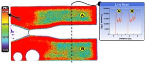
Figure 3: A cut-through of the film reveals stripping and gutting punch forces.
The line scan represents cross-sectional forces.
High-pressure areas near the cutting edges are caused by local material strip deformation. The film can be further quantified by using a tactile force analysis system. All images in this article were analyzed with this system, which renders 2-D and 3-D images; line scans; histograms; and average, minimum, and maximum pressures.
Film History
So far the film has been used in shops to measure the surface contact pressure of tools such as clamps, bolted joints, and gaskets and in mold-making applications to check for proper alignment. However, the film has not been marketed extensively for metal forming applications.
The film’s first foray into metal forming on a small shop press and die tooling revealed the sensor film would respond to 12 tons of pressure. Further calculations showed that the film could be used in larger stamping applications, as much as 400 tons.
The pressure limit for the film is in relation to the size of the metal forming and holding contact areas. The minimum bending and coining forces required need to be established individually in the die to be pressure-examined.
Testing Pressure Variations in the Die
Although significant effort goes into the design and planning of the balancing event in the stamping tool, verifiable data for new tooling can be obtained only in a press, ideally near completion of the die build phase and the first full strip press tryout. It also is a suitable analytical tool for existing tooling.
The film reveals the areas that are doing most of the work in the die station and provides important data during the metal bending preform die operation. The precise pressure distribution and actual pressure values in the die (see Figure 4) allow maintenance personnel to make corrections, such as adjusting the springs or changing the amount of contact forming pressures in the die, to fix imbalances or excessive pressures before die-build completion. The cutting edges in the gutting operation, compared to the restrike forms, show similar pressures and are similarly adjusted.
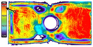
Figure 4: The film shows tactile analysis of the curved restrike operation.
In Figure 5, the film shows the dies’ outer four bumper blocks, the principal indicators of die parallelism. The film reveals data about differences in pressures across the small sections of bumper blocks, unlike traditional lead check, distance-only measurements.
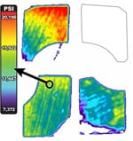
Figure 5: Three of the four bumper blocks had pressure ranges between 7,000
and 20,000 PSI. The fourth block did not have any contact, so a shut-height correction was made.
The general problem with bumper blocks is that the die should not contact these blocks at all or beyond an established pressure range; however, if this is measured conventionally with lead-free round solder, no difference can be found after the zero point of contact has been reached. The pressure-indicating sensor film still reads a pressure until the limit has been exceeded.
The test proved that bumper blocks, areas near cutting edges, gradual forms, trim cutting edges, and restrike stations all can be thoroughly analyzed, providing vital information that enables better die balancing. Even thick (more than 0.080 in.) automotive and other stamping and value-added assembly applications are measurable, from dies that stamp copper tabs inside car light switches to stamped closure components.
Uses
The film will be explored further to see how well it will work within dies, particularly progressive dies because of their high maintenance costs. For large dies, it is vital to know what pressures are in key areas of the tool to ensure that the die can run for long periods of time. This information is important not only in the build phase, but also during verification after setup inside the press. If an area has been reworked and is new in the tool, it can affect other areas of the die that operators can’t see and consequently will not know about until it is too damaged. The film can indicate whether the setup is correct and possibly indicate if the setup can be adjusted, which usually is done by a slight adjustment of the press. That will affect tool longevity and maintenance costs.
The limitations of bending also should be explored, because two contacting surfaces aren’t always flat— quite often they are curved. This test was conducted with a slight curve. It is important to find out how the film will behave under extreme curves or corners where metal is being formed.
Mirco Graenert is owner of Mirco Graenert Consulting Inc., 3-580 Steven Court, Newmarket, ON L3Y 6Z2, Canada, 905-715-7508, www.canstampconsulting.com.
Shawn Eeles is general manager of Five Star Tooling, 19 Allaura Blvd., Aurora, ON L4G 3N2, Canada, 905-841-8233.
The film, called Pressure®, is distributed in the U.S. by Sensor Products Inc., 300 Madison Ave., Madison, N] 07940, 800-755-2201, www.sensorprod.com. In Canada, it is available from Mirco Graenert Consulting Inc.