

Article
Related Links
Henning Jonathan Mostert
Bachelor of Engineering, Pu for Che 1993
Master of Engineering (Bio-engineering), University of Pretoria, 1995
BA Theology, University of Pretoria, 1999
B Div, University of Pretoria, 2001
The aim of this study was to investigate the effect of reverse shoes, partial dorsal hoof wall removal and polystyrene solar support on the biomechanics of the front hoof of the horse. Laminitis is a systemic syndrome that ultimately affects the sensitive lamellae and papilla of the hoof, causing severe pain, and often leading to disruption of the lamellae-hoof wall interface. Degeneration of the lamellar interdigitation occurs and the distal phalanx (P3) separates from the hoof wall. This can cause P3 to rotate towards the sole and, in more severe cases, P3 separates totally from the hoof wall and sinks downwards. Chronic laminitis usually results in the end of the animal’s athletic career and may lead to humane destruction.
During an in vitro study, three clinically healthy horses were euthanased and their dismembered forelimbs were used. A reverse shoe was applied and three polystyrene pads with a density of 32 kg/m3, thickness of 60mm and wedges of 66%, 50% and no wedging, respectively, were used in this study. Fuji Prescale Super and Ultra Super Low-Pressure film was used to indicate the pressure distribution of the polystyrene on the solar surface of the hoof. Two load cells were used to measure the load borne by the hoof wall and the solar area, respectively. A constantly increasing force with a maximum of 66% of the bodyweight of the horse was applied to the amputated limb by means of a tensile testing machine. A total of four experiments were done on each limb.
The results of this investigation showed that for all three of the polystyrene paddings, approximately 75 – 80% of the total load applied was borne by the solar area. The colour changes on the pressure film showed that most of the load of the 50% and 66% wedged polystyrene was borne by the palmar half of the solar surface, and less pressure by the dorsal half. For no wedging, the pressure distribution over the solar surface was even. The reverse shoe with the 66% and the 50% wedged polystyrene pads was shown to be useful in distributing the pressure to the palmar area of the sole.
During an in vivo study, the effect of different densities (32 kg/m3, 24 kg/m3 and 16 kg/m3) and different thicknesses (100mm and 60mm) of polystyrene padding, with a wedge of 50%, on the load distribution of the solar surface and the hoof wall was investigated. Compression of polystyrene over time and the effect thereof on the load distribution was determined.
The front hooves of three clinically healthy horses with a mean bodyweight of 551 kg, were trimmed and shod with reverse shoes. Reference data was recorded with only the reverse shoes on the hooves. Further data recording was done for the different polystyrene pads. Data was recorded for 4 seconds with a frequency of 50Hz. Between the treatments, the horses walked for 5 minutes on a concrete surface. This procedure was repeated 5, 10 and 15 minutes after application of the pads.
All the results of the solar pads used in the in vivo study showed a hyperbolic tendency in which the initial load was high and then diminished with time. Initially, treatments 5 (32 kg/m3 x 60 mm) and 3 (16 kg/m3 x 60mm) proved to be the better treatments, but after 15 minutes no significant different was found between the treatments. From the observations made during the experimental procedure, the 32 kg/m3 x 60mm (treatment 5) compressed to a more dense and rigid end-product than the 16 kg/m3 x 60mm (treatment 3). The compressed pad of treatment 3 was more elastic and may have contributed positively to reducing the compression of the pads on the blood vessels underneath P3.
Observations made during the experimental procedures indicated that polystyrene with a thickness of 100mm, is not recommended. This polystyrene was very uncomfortable for the horse immediately after application. Some polystyrene compressed outside the solar surface and was therefore not adequate for the object of the study.
It was concluded that polystyrene pads with densities of 32kg/m3, 24kg/m3 and 16kg/m3 and thicknesses of 100mm and 60mm would prove similar support for the remainder of the period that they were applied follow a variable compression phase of less than 15 minutes. Further research need to be done to investigate the effect of the polystyrene pad on the solar surface for a longer period.
Chapter 1 – General Introduction
Laminitis is a systemic syndrome which ultimately affects the sensitive lamellae and papilla of the hoof, causing severe pain, and often leading to disruption of the lamellae-hoof wall interface5,6,51,65. Degeneration of the lamellar interdigitation occurs and the distal phalanx (also referred to as P3) separates from the hoof wall. This can cause P3 to rotate towards the sole and in more severe cases P3 separates totally from the hoof wall and sinks downward5,6,38,51,59. Chronic laminitis usually results in the end of the animal’s athletic career and may lead to humane destruction.
The exact pathogenesis of laminitis is not known. Proposals for possible mechanisms that lead to the development of laminitis, include major damage to the lamellar basement membrane because of critical proteolytic events47,48,49,51,63, lamellar ischemia as a result of arterio-venous shunts in the hoof6,42,51,60,63 and platelet deposition and thrombosis6,63. Vasoconstriction within the digit, peri-vascular oedema, vascular perfusion defects30, and digital veno-constriction6,38 are also pathophysiological mechanisms proposed to cause laminitis6,27,38,59. Inflammatory mediators generated in organs like the gut, uterus and the skeletal musculature may cause laminitis when they reach the foot via circulation. They may act directly on the lamellar tissue, or may initiate reactions within the foot that begins the process of lamellar separation47.
Laminitis research is being conducted on two fronts: Firstly, the aetiopathogenesis of the disease, knowledge of which could halt the progression of the disease to the chronic phase and secondly, the biomechanics of the hoof in order to understand what treatments may minimise further damage to the lamellae, reduce pain and assist the healing process. In a healthy horse, the entire weight is suspended from the sensitive lamellae – in effect the horse hangs on the hoof wall. The sole is not supposed to bear any weight. The damaging of some of these lamellae causes more strain on the rest of the lamellae which may not be able to bear the tot
al load. A solar pad will relieve some of the load on the lamellae by bearing part of the bodyweight of the horse.
The objectives of this study included:
- investigating the effect of the reverse shoe and polystyrene padding on the biomechanics of the front hoof of the horse,
- evaluation of the effect of the application of a reverse shoe and a polystyrene pad on the pressure distribution to the ground surface (solar and hoof wall surface) of the hoof. This includes the sole as well as the weight-bearing surface of the hoof wall,
- determination of the effect of pressure distribution on the sole with different degrees of wedging of the polystyrene pad,
- investigation of the effect of polystyrene pads with different thicknesses on the load distribution to the solar surface of the hoof over a time period of 15 minutes,
- investigation of the effect of polystyrene pads with different densities on the load distribution to the solar surface of the hoof over a time period of 15 minutes.
The purpose of this study was to optimise the type of polystyrene pad to be used in the treatment of laminitis.
Chapter 2 – Literature Review
2.1 Anatomy of the Normal Hoof of a Horse
The hoof with all its sensitive structures can be seen as a modification of skin35. The distal phalanx (P3) is suspended inside the hoof wall by interdigitating lamellae that surround it. Two lamellae can be classified: The dermal lamellae (sensitive lamellae) that cover the outer surface of P3, and the interdigitating epidermal lamellae (insensitive lamellae). The dermal lamellae consist of approximately 600 primary lamellae, which are oriented circumferentially around P3. Each of these primary lamellae consists of approximately 100 secondary lamellae. The dermal and epidermal lamellae interlock and these attachments are the primary forces that oppose the weight of the horse and successfully suspend P3 within the hoof20,25,51,65.
The hoof wall consists of many highly keratinised tubules, which grow from the coronary corium. The solar corium is attached to the solar surface of P320.
The lamellar vasculature is complex. Arterial blood supply to the hoof is via the medial and lateral palmar or plantar digital arteries which arise by division of the medial palmar artery9. These arteries run alongside the flexor tendons. They provide branches to the coronary corium as well as the bulbs of the heel and supply the frog, the bars, the palmar coronary corium and palmar periople, the lamellae of the heel, the digital cushion and the lateral cartilage. The dorsal artery of P3 transverses the foramen in the palmar process of P3 and penetrates P3 approximately halfway to its dorsal surface to anastomose with the terminal arch. Approximately nine vessels routinely originate from the terminal arch and penetrate the distal aspect of the dorsal half of P3, forming the circumflex artery. The dorsal lamellar arteries, which perfuse the dorsal lamellae, originate from the circumflex arteries and the terminal arch. Bloodflow in the dorsal lamellar arteries is distal to proximal against the force of gravity20,25,30,51,65. The blood flows through the lamellae to the veins20. The corium of the sole is supplied by the solar plexus, which is formed by branches from the circumflex artery. This means that blood supply to the sole arises on the dorsal surface of P3 and then wraps under the distal margin of P3. It is therefore prone to damage from compressive forces. There are no major arterial branches directly under the frog20,25,30,51,65.
There are three interconnected valveless venous plexuses in the foot. They are the dorsal venous plexus, which lies in the deep part of the dermal lamellae, the palmar/plantar venous plexus, which lies in the deep part of the solar corium and on the inner axial surfaces of the cartilage of the distal phalanx, and the coronary venous plexus, which lies in the coronary cushion covering the digital extensor tendon and the outer abaxial surfaces of the cartilage of the distal phalanx9. The medial and lateral digital veins drain these three plexuses.
2.2 Forces Operating on the Normal Hoof
The inherent biomechanical factors that are responsible for the maintenance of normal functioning of the structures in the hoof, include distractive and supportive forces of P3. (see Figure 1)
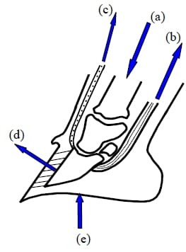
Figure 1: Distractive and supportive forces of the distal phalanx (P3). a) The downward load exerted by the weight of the horse through the bony column and distributed through the distal phalanx, b) the proximal-palmar pull of the deep digital flexor tendon from its insertion on the flexor surface of P3, c) the pulling force of the common digital extensor tendon, d) the lamellar attachment between P3 and the hoof wall and e) the distal phalangeal supportive function of the sole and frog.
The distractive forces of P3 include: the downward load exerted by the weight of the horse through the bony column and distributed through the distal phalanx25,31,32,33,58 (a), the proximal-palmar pull of the deep digital flexor tendon from its insertion on the flexor surface of P325,31,32,33,58 (b).
The supportive forces of P3 include: the pulling force of the common digital extensor tendon25,32,51 (c), the lamellar attachment between P3 and the hoof wall25,31,32,51 (d), the distal phalangeal supportive function of the sole and frog25,31,32,65 (e).
2.3 Aetiology of Laminitis
The aetiology of laminitis is multifactorial and will not be discussed5,6,19,21,46,51,59,60.
2.4 Pathogenesis of Laminitis
Currently, there are no predictive indices to determine whether a horse will develop laminitis after exposure to the inciting cause31,50.
2.4.1 The Developmental Phase
2.4.1 The Developmental Phase
This phase begins when the horse comes in contact with the inciting agent and ends with the first clinically evident signs of lameness51,57. Systemic, as well as non-systemic, insults may be inciting agents for laminitis57. The developmental phase generally lasts between 24 and 72 hours. Previous research has shown that two main pathological changes occur during this phase20,65. There is vascular shunting and also coagulopathy, causing ischaemia to the secondary lamellae which results in laminitis. Pressure-mediated fluid filtration is more likely to cause lamellar oedema than the increase in vascular permeability37. During the initial phase, there is an increase in blood-flow to the hooves, but a decrease in the perfusion of the lamellae. Permanent lamellar damage and movement of P3 within the hoof usually do not occur during this stage5,50.
Recent research, however, shows that proteolytic events occur during the developmental phase of laminitis which initiate lamellar separation and the degradation of the lamellar basement membrane. A sub-lamellar vasodilation does occur during laminitis, but does not play as important a role as previously believed47.
2.4.2 The Acute Phase
This phase begins with the first onset of clinical signs. Separation of the lamellae and displacement of P3 may occur5,65. The clinical signs may include a ?bounding digital pulse, warm hooves, abnormal gait and a painful response over the toe region when being exposed to hoof testers5,51.
The collateral circulation of the dorsal coronary corium, dorsal dermal lamellae and dorsal solar corium is less extensive than that of the palmar coronary corium, pa
lmar dermal lamellae and palmar solar corium, and these locations are sensitive to decreases in digital blood flow27. The pain that develops stimulates the adrenal gland to release catecholamines which act on alpha-receptors in the dermal vasculature within the hoof, causing vasoconstriction and decreased blood supply to the digit38,60. Necrosis of the basement membrane and separation of the dermal lamellae cause an imbalance of the normal biomechanical forces, and the remaining lamellae shear away from the hoof wall19,38. This deterioration of the lamellae, together with the downward load exerted by the weight of the horse, as well as the proximal-palmar pull of the deep digital flexor tendon, are responsible for the displacement of P331,33. Initially during the developmental phase of laminitis the lamellae stretch, resulting in a downward movement of P3 within the hoof19,38. If the lamellar insult is severe enough, the important interlamellar bonds between the dermal and epidermal layer will be destroyed and result in distal displacement of the distal dorsal tip of P3. The distal rotation of the distal dorsal tip of P3 results in the loss of the parallel relationship between the dorsal hoof wall and the dorsal cortex of P3. Due to the detachment and stretching of the interlamellar bonds, spaces are created and gas extravasates into these spaces33.
2.4.3 The Chronic Phase
Chronic laminitis occurs when there is a distal-palmar rotation of P3, and/or a distal sinking of P3 relative to the hoof wall surrounding it. Once these mechanical changes have occurred within the hoof, the prognosis becomes poor5,51,65. Displacement of P3 relative to the hoof wall causes the dorsal submural and coronary circulation to be subjected to shearing forces that will affect the circulation30,51. The solar dermis is subjected to increasing compressive loads as it is trapped between the sole and P3.
If and when rotation of P3 occurs, it can vary from mild to severe. Severe rotation is often associated with separation of the coronary band over the extensor process region60. When the lamellar bonds at the dorsum fail, the pull of the deep digital flexor tendon and the lamellar bonds of the quarter and heel sections causes rotation of the distal dorsal tip of P3 towards the sole27,51. In severe cases the rotation of P3 causes the distal dorsal tip of P3 to penetrate through the sole51,59,60. If the lamellar bonds all the way around the interior of the hoof loosen, P3 as a whole may displace distally. Such cases are referred to as sinkers51,60.
2.5 Symptoms of Horses Suffering from Laminitis
Laminitis may occur in one, two, three or all four hooves in any combination, but is more common in the front hooves5,6,20,46.
2.5.1 Clinical signs of laminitic cases
Pain, as a result of distracting or compression forces of the sensitive structures in the hoof, is the most important clinical finding. Obel clinically characterised and graded the severity of lameness using the following criteria32,37,38:
Grade 1: At rest the horse will shift weight occasionally. No lameness is evident at a walk, but a short stilted gait is noted at a trot,
Grade 2: Horses move willingly at a walking pace, but the gait is stilted. A hoof can be lifted off the ground without difficulty,
Grade 3: The horse moves reluctantly and resists attempts to raise a limb,
Grade 4: The horse is recumbent most of the time, is in pain and has to be forced to move.
Other symptoms include the typical stance, bounding digital pulse, and sweating. Indentation at the coronary band (sinkers), flattening or bulging of the sole, penetration of the sole, oozing at the coronary band, elevated hoof wall temperature, pain detected over the toe region with hoof testers, are all signs associated with laminitis5,6,57,62. Most horses become sound after administration of a basilar sesamoid nerve block6,33. The nerve block will, however, cause further mechanical damage to intact lamellae due to painless movement, and is therefore not recommended20,21,. Nerve blocks may also affect the neuronal control of digital arteriovenous anastomoses and therefore potentiate digital ischaemia21. Abaxial sesamoid nerve blocks release the vasoconstrictor tone of the blood vessels and cause a dramatic rise in foot temperature, which increases inflammation of the lamellae47.
2.6 Diagnosis of Laminitis
The diagnosis of laminitis can be made from the history, clinical symptoms and radiographs of the hooves5,42,59,62.
2.6.1 Radiography and radiology of the hoof of a horse with laminitis
The relative positions of the structures in the hoof can only be identified by means of radiographs59. Latero-medial radiographs are the most useful. This projection highlights the dorsal, palmar and solar surfaces of the phalanges and the interphalangeal joints. The hoof wall and sole thickness can also be identified by this projection40. The solar surface of the hoof must be cleaned and loose horn removed. A drawing pin needs to be placed at the apex of the frog to indicate the position of the frog relative to the distal dorsal tip of the pedal bone on the radiograph. This marker can however be misleading for the exact location of the apex may be hidden under an overgrowth of frog tissue55. The apex of the frog must be carefully trimmed beforehand to observe the frog blending in the sole. At this specific point, the colour of the frog is darker than the sole43,44. The dorsal wall must gently be rasped to remove loose or excessive horn and create a flat dorsal surface. A stiff straight metallic marker, like a piece of bale wire, of known length is then attached to the most dorsal point of the dorsal hoof wall with the upper end where the wall horn merges with perioplic horn44. The wire must be positioned so that it is symmetrical with the tip of the frog. The length is important for the correction of radiological magnification. Barium paste may also be used55. The animal must be radiographed standing squarely on a flat wooden block, thick enough to bring the solar surface of the foot level with the centre of the xray beam, with a wire marker that indicates ground level55. When the horse steps onto the block, the other limb must be lifted. The centre of the radiograph beam (collimator) should be kept horizontal, and centred on the distal phalanx, at approximately the region of the deep digital flexor tendon attachment, a point approximately midway between the coronary band and the ground surface at the junction of the dorsal and middle thirds of the hoof7,55. The beam should be aligned parallel with a line drawn across the bulbs of the heel7. It has to be parallel to the top of the block and perpendicular to the axis of the limb, so that a true latero-medial radiograph is produced6,9,20,21,59. To avoid magnification errors, a constant distance between the hoof and collimator is recommended15,55.
In the balanced hoof, the lateral radiographs show the phalanges to be in a straight line. The wire marker placed on the hoof wall is parallel to the dorsal surface of P3. There is a 5 to 10 degree slope between the solar surface of P3 and the bearing surface of the hoof7,59.
Radiological features of laminitic cases without rotation are related to separation of P3 from the hoof. There is an increased distance between the dorsal hoof wall and P340. Radiological features of horses suffering from rotation show a distal and palmar movement of P3 within the hoof. The parallel relationship between the dorsal cortex of P3 and the dorsal hoof wall is lost.
There is an increased vertical distance between the upper end of the wire and the extensor process in sinkers as well as rotators5,7,19,20,33. A soft tissue indentation along the coronary band may be seen or palpated5. Lamellar thickening and gas accumulation along the dorsal lamellae, lysis, hypervascularity and remodelling of P3 are all indicators of long-duration chronic laminitis33,40. Penetration of the sole by P3 as well as subsolar abscessation filled with gas may be observed on the radiographs of a horse suffering from chronic laminitis33.
For “sinkers” the entire P3 drops within the hoof. This, however, is difficult to observe from radiographs, as the dorsal wall of the hoof and the dorsal surface of P3 remain parallel. The distance between the coronary band and P3 and the indentation at the coronary band, can assist in the diagnosis of “sinkers”7, as well as an increase in the distance between the pedal bone and the dorsal hoof wall.
According to Eustace et al, three angles, namely the angle of the hoof wall with the ground surface (H), the angle of the dorsal surface of the pedal bone with the ground surface (P) and the angle of the bony column with the ground surface (B) can be measured from radiographs. The degree of rotation of the pedal bone (Angle R) and the degree of rotation relative to the long bone (Angle L) can be calculated (Figure 2) )20.
Angle R = Angle P – Angle H
Angle L = Angle P – Angle B
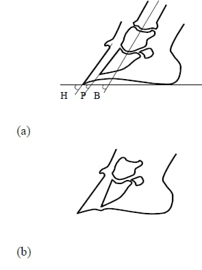
Figure 2: Cross-section of the hoof of (a) a normal horse and (b) one suffering from laminitis. H, P and B are the angles that need to be determined to calculate the degree of rotation of the distal phalanx (P3).
2.7 Treatment of Laminitic Cases
The wide variation in the therapeutic approach to laminitis is indicative of our lack of knowledge and understanding of this complex condition.
The aim in treating laminitis must be to:
- treat the initiating cause if known and if still present5,6,12,21,57,59
- relieve pain5,6,19,59,
- re-establish the normal circulation to the hoof and hoof structures6,12,16,27,59,
- prevent further damage of the sensitive structures in the hoof5,6,14,33,59,62,65,
- increase the other supportive structures when the lamellae are damaged, the other supportive structures must be increased in order to maintain skeletal support12,33. Frog support may assist in the arrest of the rotation or displacement of the pedal bone9,21,58,60,
- encourage new hoof growth19,59,65,
- restore the parallel relationship between the hoof wall and P316,27,60 and
- prevent infection5,16,27,59.
It is important to follow a holistic approach in the treatment of a horse suffering from laminitis.
2.7.1 Treatment of the Developmental Phase of Laminitis
The treatment during this phase is of a preventive nature and is based on the probability of the onset of laminitis. The objectives of the treatment include elimination of the inciting cause and decreasing of the blood-flow to the hoof by cooling and preventing or minimising the effect of collagenase or dissolution of the basement membrane41,57,65. When more is known about the exact molecular mechanism of laminitis, a treatment which inhibits lamellar separation can be developed47.
2.7.2 Treatment of Acute Laminitis
During this phase, treatment is directed towards the relief of pain, prevention of the displacement of P327,41,57,65 and the treatment of all affected systems which may include septicaemia and shock66. In sub-acute laminitis, lamellar damage may be minor and the horse may recover completely and the situation may not progress to a more acute phase5. The horse should be placed in a stall with sand or soft bedding to minimise concussion to the hooves which will create frog pressure. Encourage the horse to lie down5,51.
Therapeutic approaches to prevent further displacement of P3 are based on supporting the skeletal column by packing the sole with various materials, frog support, the use of therapeutic shoes (heart-bar shoe, reverse shoe and others), dorsal hoof wall removal and surgical approaches (deep digital flexor tenotomy)5,41,65. Care must be taken not to apply too much pressure to the sole and the frog which could disrupt the solar circulation. The material must be applied to distribute pressure evenly65. Preventing or delaying displacement of P3 minimises further damage to intact lamellae.
2.7.3 Treatment of Chronic Laminitis
This stage of laminitis needs to be handled with extreme care. The following decisions need to be made: 1) What type of therapeutic shoe or non-traumatic application will be the best for the specific case? 2) Should the temporary hoof support be maintained or replaced? 3) Does the horse meet criteria elected for euthanasia57? In an attempt to normalise the vascular perfusion and correct spatial orientation between P3, the hoof wall and the sole, therapeutic trimming is implemented27,65. Therapeutic trimming will also be effective for the normalisation of hoof growth and of exposure to sepsis27. When displacement of P3 occurs, the therapy for this phase depends on the severity of damage to lamellae within the digit, as well as the degree of rotation or displacement of P3. Therapeutic approaches may include hoof wall removal and corrective shoeing65.
2.7.4 Trimming techniques for Laminitis
Correct trimming is important for the treatment of laminitis59.
2.7.4.1) Medio-lateral balance:
Medio-lateral hoof balance can be established by ensuring the correct relative lengths and angles of the medial and lateral walls of the hoof1,2. Inappropriate medio-lateral balance causes uneven load distribution in the hoof. The medio-lateral balance is established by trimming the ground surface of the hoof perpendicular to the long axis of the limb (geometric balancing), or trimming the ground surface of the hoof so that the medial and lateral aspects of the heel land simultaneously (dynamic balancing) 1,2,6,59.
2.7.4.2) Dorso-palmar balance.
For proper trimming, the silhouettes of the dorsal surface of the hoof and the pastern regions need to be parallel. For low hoof angles, either toe needs to be removed, or if not possible, the heels need to be elevated.
2.7.4.3) Raising the heels:
For laminitis cases with rotation, the rationale for raising the heels is to reduce the pull of the deep digital flexor tendon (DDFT). The load on the lamellae also seems to be reduced54. Methods to reduce the pull of the DDFT vary from non-invasive to invasive, i.e. raising the heels to severing the DDFT.
Wedges are applied to the hooves of the horse to match the required angle54. Knowing the optimal limit for elevation of the heels is essential. Elevation of 180 reduces the pull of the deep digital flexor tendon significantly54. Excessive elevation could change the orientation and vertical load exerted on P3 by P2 and create a potentially destructive shearing force between P3 and the hoof wall36. When raising the heels, the secondary effects on the fetlock angle must also be considered because changes in this angle may affect the deep digital flexor tendon and the extensor branch of the suspensory ligament to the extensor process. The strain on the flexor tendons and the suspensory ligament does not change when the heels are e
levated, because a decrease in load through the suspensory system and its extensor branch would reduce the force on the extensor process and thus limit any possible counterbalancing force to rotation36.
Advantage:
1) Decreases the tension of the deep digital flexor tendon6,60.
Disadvantages:
1) Disturbs toe-heel balance60,
2) Focuses compression weight-bearing forces on the extensor process and on the distal dorsal tip of P360,
3) When the heels are raised, the lamellae are aligned more perpendicular to the ground surface, and this may result in the sinking of the bony column. It also changes the orientation and vertical load exerted on P3 by P2, creating a potentially destructive shearing force between P3 and the wall9,45.
2.7.4.4) Deep digital flexor tenotomy.
Tenotomy of the DDFT totally eliminates the pulling force of the tendon and can be performed in the palmar- plantar aspect of the pastern, or in the mid-metacarpal/metatarsal region6.
A small incision is made through the skin, subcutaneous tissue, and sheath of the DDFT. While the distal limb is flexed to relax the tendon, a pair of curved haemostats is used to isolate the tendon. The DDFT can be transected with a scalpel blade. The tendon sheath may be closed with absorbable sutures, or left open33.
Advantage:
1) Removes all pull in DDFT, and therefore prevents further rotation of P36.
2) Relief pain18.
Disadvantages:
1) The athletic career of a horse will come to an end after DDFT tenotomy as the animal will not be able to perform to the same standard as before. This procedure can therefore only be performed in animals suited for breeding27
2) Scar formation may occur at the tenotomy site and this is sometimes associated with pain62,
3) Requires constant hoof care afterwards since the toe grows out longer and the solar surface at the toe increases in thickness62,
4) The benefit of tenotomy only lasts for approximately one year27.
2.7.5 Hoof wall removal
The aims of hoof wall removal are the following:
- To minimise the physical laceration of the compromised lamellae along the dorsal aspect of the hoof wall and ease break-over. This helps with the prevention of further separation of P3 from the hoof wall, and further damage to the lamellae1,5. If the toe is too long, it needs to be trimmed,
- To drain fluid or abscesses,
- To remove old, dead hoof wall tissue26,27,46,
- To establish spatial orientation between the hoof wall and P326,27,46,
- To relieve pressure at the coronary band. This will enhance blood circulation and new horn growth. New hoof growth occurs mainly from the coronary corium and grows in tubules. The new growth follows the old growth distal in the hoof wall. Abnormal growth caused by laminitis will therefore be perpetuated by this growth pattern26,27,46,
- The re-establishment of normal vascular perfusion can be achieved by separation of new growth from old abnormal growth26,27,46.
Removal or thinning of the dorsal hoof wall is important in horses with excessive distal phalangeal rotation (more than 6°) and sinking (more than 0.5cm), slight rotation or sinking that increases with time and when sepsis is present27,52,65. Redden disagrees with this statement and questions the efficacy of dorsal hoof wall removal53. He suggests drilling a hole through the hoof wall for exposure of necrotic tissue and to relieve pressure associated with the accumulation of fluid.
2.7.5.1 Methods of hoof wall removal
There are two major methods of hoof wall removal: a) hoof wall removal, where a portion of the distal aspect of the hoof wall is removed with a rasp25,52,64 or a circular sander25,64, or b) hoof wall stripping, which is the removal of full-thickness sections of the hoof wall25,26,27.
2.7.5.1.1 Dorsal hoof wall removal:
Dorsal hoof wall removal can be done in 3 grades: a) distal 3rd, b) distal 2/3rds, and c) total removal. When a rasp is used, the hoof wall is removed dorsally, dorso-laterally, and dorso-medially. For total removal of the hoof wall, removal starts approximately 1.0 to 1.5cm distal to the coronary corium, and proceeds distally to the weight-bearing surface25,26,52,64. One can also start distally at the toe and work proximally until all dead epidermal tissues is removed. Approximately the dorsal third of the hoof wall circumference needs to be removed26,27, more than this may severely compromise the wall stability33. The hoof wall is gradually removed until the tissue that remains is somewhat soft, spongy to the touch, and pinkish-white22. Most of the necrotic brown-coloured haemorrhagic lamellae will be removed in the process25,26,52. One should avoid penetration of the sole and the underlying tissues, unless they are undermined and necrotic52. Daily examination of the hoof and cleanliness is essential to minimise complications such as infection.
Advantages:
- Hoof wall removal or trimming will ease break-over of the hoof, which in effect reduces the strain of the deep digital flexor on P3 and reduces the possibility of mechanical tearing of the remaining intact sensitive tissues46,
- The procedure for dorsal hoof wall removal does not normally require general anaesthetic, as live tissue is not invaded20,
- It will reduce or can even remove the pressure-induced ischaemia at the coronary corium and will therefore ease growth of the coronary corium. Hoof wall removal alleviates the compressive forces on the dorsal coronary corium16,25,27,
- Enough hoof wall is left for the application of a therapeutic shoe9,25,26,27,
- This technique exposes necrotic tissue and effects drainage of infected lamellae8,9,25,52,65
- The status of the lamellar tissue can be evaluated,
- The removal of dead horn allows the new growth from the coronary corium to realign with the sensitive lamellae and can prevent lamellar wedging6,25,26,27,46,62,64
- It normalises the spatial orientation of the dorsal hoof wall with P3.
Disadvantages:
- Dorsal removal requires a relatively long convalescence, depending on the amount of hoof wall removed46,62,
- Redden questions most of the advantages of dorsal hoof wall removal noted above53. He states that P3 rotation does not have an influence on hoof growth, therefore removal for this reason is unnecessary,
- Redden also questions the approach of removing exposed necrotic tissue. Sometimes only one third of the necrotic tissue can be exposed during hoof wall removal53.
- Wall resection cause a lost of structural integrity of the hoof capsule and therefore destabilise the hoof capsule16.
2.7.5.1.2 Hoof wall stripping
For dorsal hoof wall stripping, the hoof must be locally anaesthetised. A burr can be used to groove the hoof distally on the white line, proximally (depending on how much of the wall tissue needs to be removed), on either side of the section to be removed. The depth of the grooves is increased until the sensitive lamellae are reached. The hoof wall is then grasped with shoe pullers distally and lifted off in a proximal direction. An appropriate wound dressing is applied until the exposed area has keratinised sufficiently25,26.
Advantages:
- Hoof wall stripping can be b
eneficial in hooves with submural abscessation with or without secondary drainage and with separation at the hair-periople junction25, - Other advantages are the same as with wall removal or trimming.
Disadvantages:
- Stripping of the dorsal hoof wall causes a lot of trauma and pain to the hoof, and is not recommended for general treatment of chronic laminitis27,33,46,62,
- A long recovery period is required.
2.7.6 Therapeutic shoeing of laminitic horses
The general aims for therapeutic shoeing of horses with laminitis are to change the weight distribution in the hooves in an attempt to64:
- reduce pain27,33,45,
- decrease strain on compromised lamellae27,33,
- prevent or minimise P3 rotation or sinking6,25,64, and
- enhance circulation to the coronary band and stimulate balanced hoof growth6,64.
- Transfer load to the less affected part of the wall45.
Most commonly used shoes include non-adjustable and adjustable heart-bars25, reverse shoes with pads64, reverse shoes with heart-bars, egg-bar shoes with and without heart-bars, regular shoes with different pads5, other shoes with pads52.
2.7.6.1 Heart-bar shoe
Adjustable and the non-adjustable heart-bar shoes are used in practice for frog support20,22,25,27,28. The non-adjustable heart-bar shoe, is a bar shoe with a sagittal frog plate (heart-bar) extending dorsally from the bar, with an incline that puts pressure on the frog after it has been nailed into position. The adjustable heart-bar shoe has an adjustable heart-bar, hinged on a sleeved tube on a rounded bar. The incline of the heart-bar can be adjusted with an Allen screw without re-shoeing the horse28. For both the adjustable and non-adjustable heart-bar shoe, the hoof is trimmed and large portions of dorsal hoof wall may be removed, the sole is made concave, and the frog is trimmed to maximise the surface area in contact with the heart-bar. The cranial point of the heart-bar shoe is positioned approximately 1.3 to 1.9 cm palmar to the dorsal aspect of the distal dorsal tip of P328. Failure to adhere to this may result in rotation. The heart-bar shoe should be 0.15 cm narrower than the medial and lateral extent of the frog and should not exert pressure on the sole. The pressure of the bar on the frog is then adjusted to be as great as possible, without significantly worsening the lameness. After shoeing, the hoof must be covered with elastic tape to prevent accumulation of debris around the bars of the shoe27. Pressure adjustments must be made once or twice a week, and the heart-bar shoe must be reset, usually at 6- to 8- week intervals28.
Advantages:
- The heart-bar shoe supports and stabilises P3 by supporting the frog23,25,
- Redistribution of weight-bearing on the frog and hoof wall can be accomplished by adjusting the pressure exerted on the frog by the frog plate, to the optimum pressure. Thus, the adjustable heart-bar shoe is of more therapeutic value than the non-adjustable heart-bar shoe27,
- The heart-bar shoe decreases the pressure exerted by P3 on the solar vascular plexus and therefore increases digital perfusion25,28. The pressure applied by the heart-bar shoe minimally affects remaining digital perfusion, because there is an absence of major blood vessels in the area when pressure is applied25,
- It attempts to decrease further tissue damage and alleviate pain during hoof regrowth25,28.
Disadvantages:
- The frequent removal and reapplication of the shoe damages the already sensitive hoof wall and is a painful procedure27. The adjustable heart-bar shoe is more beneficial than the nonadjustable shoe as it does not need to be replaced as often28,
- The estimation of the optimal pressure can be difficult, especially for the non-adjustable heartbar shoe. Too much pressure can cause increased lameness and too little pressure negates the benefit of the shoe25,27,
- It is difficult to maintain optimal pressure on the frog with the non-adjustable heartbar shoe because as the heel grows out, the pressure on the frog decreases25,27,28,
- Heart-bar shoes do not stabilise or prevent distal phalangeal rotation in all acutely or severely affected horses, and have not been significantly rewarding39,
- The use of heart-bar shoes without dorsal hoof wall removal, leads to increased pressure beneath the dorsal hoof wall, causing increased lameness23,
- Solar or circumflex vessel compression from the heart-bar if placed too far dorsally, can cause regional ischaemia and solar necrosis25. If the heart-bar extends too far abaxially, palmar or plantar vessels may be occluded at, or before they extend through, the bony foramen at the entrance of the semilunar canal, resulting in digital ischaemia25. If the heart-bar is wider than the frog, it may occlude the palmar or plantar digital artery28,
- The heart-bar shoe can accelerate cellular death and lamellar breakdown if not used properly52,
- Cross-treading of the Allen screw or the support bar may cause difficulties25,27,
- Formation of abscesses or granulation tissue can occur under the heart-bar if applied incorrectly25,27,
- The shoe is technically difficult to make and apply16,58,
- Horses with subsolar haematomas or abscesses cannot be treated with the heart-bar shoe25,
- The mechanical pressure used to force the coffin bone into a normal angle will cause some degree of necrosis of the frog53,58,
- The pressure applied to the sole is very concentrated and may cause further damage to the frog, the sole and the blood flow28,
- Radiographs are needed for the correct placement of the heart-bar Shoe16.
2.7.6.2 Reverse shoe
The main effect of the reverse shoe is to redistribute the load to the more palmar aspect of the hoof, which is usually less severely affected. This shoeing method results in a more even pressure distribution that will enhance even growth of the hoof from the coronary band42,62. A modification of the reverse shoe is the reverse even-frog pressure shoe (REFP). The REFP is a combination of the adjustable heart-bar shoe and the reverse shoe. It has an adjustable steel frog plate that is parallel to the frog, so that the pressure on the frog is a uniform pressure applied to the entire bearing surface of the frog42. A properly sized shoe must be fitted toe-to-heel, reversing the normal position so that any remaining hoof wall at the toe does not have contact with the shoe.
Advantages:
- The reverse shoe displaces the centre of gravity of the horse palmarly, and in effect moves the weight-bearing on the digit palmarly and removes weight-bearing from the compromised dorsal laminae42,
- Minimal weight is transferred to the dorsal coronary band and results in more normal alignment of the new growth of the hoof in the toe area8,42,62,64,
- The open toe eases the break-over at the toe and decreases the shearing force at the P3-hoof wall interface42,
- With the reverse even-frog pressure shoe, more frog support is possible and an increase of the frog pressure decreases total weight-bearing on the hoof wall42.
Disadvantages
- If the tip of the frog plate of the REFP shoe is too palmar to the solar pivotal point of P3, rotation of P3 may occu
r42, - There is uncertainty about the correct placement of the shoe in relation to P3.
- The reverse shoe does not stabilise P39,
2.7.6.3 Solar support
This approach transfers some load-bearing from the hoof wall to the solar surface.
Support of the hoof, especially support of the sole and frog has been recommended27. Various methods of sole support have been documented, which include plaster of Paris, (3M), standing the horse in sand or mud, or packing the sole with acrylic or silicone caulking or sponge rubber. These are all methods for distributing the load evenly over the sole64.
When using acrylic or silicone caulking, a reverse64 or heart-bar66 shoe is nailed onto the hoof, with a leather or plastic pad between the hoof and the shoe. The acrylic or silicone caulking is then injected between the pad and the sole, to provide a cushion between the pad and the sole.
A hoof pad with a solar pad was designed for the treatment of laminitis and is called a Lily Pad (Lily Pad, Therapeutic Equine Producs. P.O. Box 36176, Indianapolis, IN 42636). The proposed action of Lily pads is to stabilise P3. They also result in an elevation of the heel and decreases tension on the deep digital flexor tendon29. In a recent study, it was found that these pads were not effective in accomplishing increased stability. This conclusion was drawn due to the absence of clinical or objective improvement29. The pads may cause a subtle mechanical compression on the sole which is mild in the beginning, but increases with time. The pads may also cause compression of the blood vessels in the solar area, which compromises the vascular supply to the hoof. The correct placement of the Lily pad is critical for the correct treatment of a horse with laminitis29.
Advantages:
- Solar support provides a more even distribution of weight away from the hoof wall29,
- Load distribution is over the entire ground surface and not limited to the frog,
- It assists in stabilising P3.
Disadvantages:
- One cannot ascertain the exact amount of pressure transferred to the sole,
- One cannot determine the effect on the blood supply of the sole,
- Rigid products may lead to solar necrosis,
- The pads need to be cut to size.
2.7.6.4 Reverse shoe, partial dorsal hoof wall removal and polystyrene solar support (RDPS).
The reverse shoe and polystyrene solar support is an attempt to combine the advantages of the reverse shoe, solar padding, the heart-bar shoe and the reverse even frog pressure shoe in the treatment of horses with chronic laminitis62. This treatment technique is proposed by the Equine Veterinary Clinic of the Veterinary Academic Hospital, Onderstepoort, and is designed to apply pressure uniformly over a large area of the solar surface of the hoof. Extremely satisfying results were obtained from clinical cases treated with this technique. The most useful characteristic of polystyrene (Sagex, South Africa) for the treatment of laminitis, is the ability of the material to deform into the shape of the solar surface of the hoof while still maintaining a certain amount of elasticity. It can therefore support the bony column and stabilise P3. Using polystyrene in a solar pad is cheap and it is readily available.
Another advantage of this technique over others is its even load distribution over the solar surface area and the hoof wall. Contouring and shaping of the polystyrene support pad is an attempt to reduce compression of the blood vessels and terminal arch vessels. Wedging of the pad is an attempt to create less pressure on the more sensitive areas, which includes the toe area, and to provide a more even distribution of pressure over the entire underfoot surface.
2.8 Experimental Bio-mechanical Models of the Distal Digit
In order to study the biomechanical effects of the RDPS technique on the digit, a review of research conducted in the fields of equine digital biomechanics and bio-kinematics is necessary.
2.8.1 Hoof wall biomechanics
Colles used foil strain gauges attached to the hoof wall to detect changes in hoof shape in shod and unshod horses13. He concludes in his study that the vertical strain measured in the hoof wall may relate to the vertical weight-bearing force borne by the hoof wall. His system is however valuable for rapidly changing strain, rather than static measurement. In another study, Douglas, et al found that the hoof wall is thinner at the quarters than on the dorsal surface, and also has a lower stiffness17. They also found that during the stance phase of the stride, the magnitude of the surface strain at the dorsal wall is not substantially different from the surface strain at the quarters. This indicates that the load at the dorsal wall is greater than at the quarters17. These findings are consistent with those of Colahan, et al11. When in vitro experiments are conducted on the hoof wall, it is important to keep in mind the change of the moisture content of the hoof wall, and the effect thereof on the measurements17,34.
Barrey used an instrumented horse shoe to measure load distribution on the hoof for different gaits3. He concludes that the anatomical regions are adapted to their biomechanical functions. The caudal region has a damping function, the central region has a supporting function for heavy loads and the cranial region has a propulsion function.
2.8.2 Biokinetic studies of the digit
Bartel, et al developed a procedure based on an analytical model to determine the internal forces in the digit of the horse4. The internal forces can be calculated from input data which includes external forces between the hoof and the ground, configuration of the digit during the support phase of gait, and the internal geometry of the digit. P3 and the navicular bone were taken as a unit. The internal forces for this unit include the force of the bony column on the coffin joint, the force due to the suspensory navicular ligament, the force due to the deep flexor tendon and the force of the ground on the hoof.
2.8.3 Solar surface measurements – Pressure Measurements
Different techniques for measuring pressures of the horse’s hoof have been developed, which include modified horse shoes3,24 and strain gauges13,61. In a recent study, prescaled pressure-sensitive film was used to determine the centre of pressure of the soles of hooves of the forelimbs of horses standing on a flat level surface11. The position of the hoof was recorded on sheets of white paper and carbon paper that were aligned with the film in a purpose-built cassette. In the experiment the animal stood with its one hoof on the cassette and the other on a wooden block of the same size. Pressures were then recorded on the film and the pressure distribution was read with a densitometer10,11. The centre of pressure was found to be located in the medial heel area of the hoof.
The advantage of this technique is that measurements can easily be made. Variables that must be dealt with during this procedure include the trimming techniques of the farrier, the effect of environmental conditions on the film, the condition of the solar surface and the hoof wall and also the behaviour of the horse10,11.
Chapter 3 – Materials and Methods
3.1 – Hoof Preparation for the Application of the Reverse Shoe
The hoof was trimmed geometrically to a point of medio-lateral and toe-heel balance. This means that the hoof was symmetrical from a dorsal, palmar and solar surface view.
3.2 – Radiograp
hy
The hoof was prepared for radiography and radiographs were taken according to the standard operating procedures of the Section of Radiology at the Academic Veterinary Hospital, Faculty of Veterinary Science, Onderstepoort.
The radiographs were evaluated for any malformations of the hooves. According to Eustace et al, three angles, namely the angle of the hoof wall with the ground surface (H), the angle of the dorsal surface of the pedal bone with the ground surface (P) and the angle of the bony column with the ground surface (B) can be measured from the radiographs20. The degree of rotation of the pedal bone (Angle R) and the degree of rotation relative to the long bone (Angle L) can be calculated
Angle R = Angle P – Angle H and Angle L = Angle P – Angle B
The distance from the distal dorsal tip of P3 to the tip of the dorsal hoof was measured. The thickness of the hoof wall was measured at two points, namely at the distal dorsal tip of P3 and dorsally at the proximal limit of the flat surface of P3. These measurements were recorded by drawing a line perpendicular to the level of the dorsal surface of P3 and then the distance between this line and the dorsal hoof wall was measured.
3.3 Partial Hoof Wall Removal
For this study, the distal 3rd of the dorsal hoof wall was partially removed using a rasp. Removal of the toe started at the most distal dorsal point of the toe, with the rasp held at an angle perpendicular to the solar surface. In each case the hoof was rasped so that the dorsal wall formed a flat plane until either the pinkish colour of the lamellae was visible, or until the dorsal branches of the shoe perpendicular to the shoe were met. The hoof wall was gradually removed until what remained was somewhat soft and spongy to the touch, and pinkish-white. Care was taken not to penetrate the sole and the underlying tissues.
3.4 Shoeing the Prepared Hoof With a Reverse Shoe
In each case, either a number 1 or a number 0 shoe was applied in the reversed position. The tip of the round end of the shoe (toe of the shoe) was in line with the vertical line along the bulb of the heels when the horse stood erect. The position of P3 was obtained from latero-medial radiographs and the heels of the shoe was positioned 1cm dorsal to the distal dorsal tip of P3 (Figure 3). This position was important to ease break-over of the foot with the pivotal point at the heel of the reverse shoe and not at the distal dorsal tip of P3. In clinical cases this position may decrease unnecessary strain on the sensitive lamellae.
Figure 3: Photograph showing the position of the reverse shoe on the hoof
3.5 Calibration of the Load cells for Use in the Experimental Procedures
The load cells (Load Cell Services, South Africa) were calibrated in a Schench 100kN Tensile Testing Machine (Calibration certificate number 5484.SFS190 SABS –Force Metrology, South Africa). A specific load was applied to the load cells and the voltage output (V) for that specific load in Newton was recorded. This volts/Newton value was used as the calibration factor for the load cells. The calibration value for the HBM-KWS 3073 strain amplifier used in this study was also recorded for the specific Volt/Newton value and was used to check the calibration of the cells during the test. During the tests, the voltage output of the load cells was recorded with a PL202 Diagnostic Instrument. After the tests, the data were downloaded with a RS232 port and were saved in ASCII format. The results were processed with the Matlab for Windows Student version 4.2 Computer Programme (The Mathworks, Inc).
3.6 Application of the Polystyrene Pad to the Prepared Hoof
A polystyrene pad was made from a square block of polystyrene which was big enough to cover the ground surface of the hoof. A print of the reverse shoe was made on the polystyrene block. The inner area of the print was cut out with a jigsaw. The dorsal end of the polystyrene was cut off 1 cm palmar to the heels of the reverse shoe (Figure 4). For the wedging, the desired percentage thickness of the polystyrene in millimetres was measured on the side of the toe of the shoe, and the polystyrene was then wedged from total thickness on the side of the heels to the mark on the side of the toe.
Figure 4: A photograph showing the position of the polystyrene pad on a hoof shod with a reverse shoe
For application to the hoof, the pad was placed in position on the solar surface of the hoof. The pad was secured to the hoof with elastic bandage (Smith+Nephew, VetBand, Adhesive Support Bandage, South Africa). Short strips of elastic bandage were placed medial to lateral and dorsal to palmar, followed by full circling of the hoof (Figure 5). The bandage did not cover any part of the conorary band, so as not to compress the blood supply to already compromised tissue.
Figure 5: A photograph showing the initial steps to secure the polystyrene pad to the hoof shod with a reverse shoe, with elastic bandage.
3.7 Purpose-Made Equipment for this Study
3.7.1 Solar plate
A solar plate was designed and made to be able to measure the load borne by the polystyrene pad filling the solar surface. The plate was made from 5mm steel. It was cut to fit into the inner area of either a number 0 or number 1 shoe. The solar plate screwed onto the top load cell so that it could measure vertical displacement caused by the load of the horse (Figure 6). The load caused by the solar area can be calculated using this vertical displacement.
3.7.2 Modified shoe
A number 0 and a number 1 shoe were modified to stabilise the foot of the horse when it stepped onto the measuring system. After the solar plate was attached to the load cell, the modified shoe was attached firmly to the cell with the plate filling the inner area of the shoe. The shoe had four spacers, so the reverse shoe on the hoof fitted firmly onto the modified shoe to stabilise the horse’s hoof (see Figure 6).
Figure 6: Modified number 0 and number 1 horse shoe and solar plate used in this study for the measurement of the load borne by the polystyrene pad and the hoof wall of a horse treated with a reverse shoe and polystyrene solar pad.
Chapter 4 – Investigation into the In Vitro Effect of a Reverse Shoe And Polystyrene Padding on the Biomechanics of the Front Hoof of the Horse
4.1 – Introduction
Laminitis ultimately affects the sensitive lamellae and papilla of the hoof, causing severe pain, and often leading to disruption of the lamellae-hoof wall interface5,6,51,65. Degeneration of the lamellar interdigitation occurs and the distal phalanx (also referred to as P3) separates from the hoof wall. This can cause P3 to rotate towards the sole and, in more severe cases, P3 separates completely from the hoof wall and sinks downward5,6,38,51. Chronic laminitis usually results in the end of the animal’s athletic career or demands humane destruction.
Therapeutic shoeing is often used in an attempt to treat laminitis. The aim of therapeutic shoeing is to change the weight distribution in the hoof in an attempt to reduce pain27,33,64, decrease strain on compromised lamellae27,33, prevent or minimise P3 rotation or
sinking6,25,64 and to enhance circulation to the coronary band and stimulate balanced hoof growth6,64.
Most commonly used shoes include non-adjustable and adjustable heart-bar shoes25, reverse shoes with pads64, reverse shoes with heart-bars, egg-bar shoes with and without heart-bars, regular shoes with different pads5, reverse even frog pressure shoes42, other shoes with pads52. Using solar pads transfers some load-bearing from the hoof wall to the solar surface. Support of the hoof, especially support of the sole and frog has been recommended27. Various methods to provide sole support have been documented, including: plaster of Paris, (3M), standing the horse in sand or mud, or packing the sole with acrylic or silicone caulking or sponge rubber64,66. The proposed action of solar pads is to stabilise P3. It also results in an elevation of the heel and decreases tension on the deep digital flexor tendon29. Solar support over the entire solar surface provides a more even distribution of weight away from the hoof wall64.
The application of the reverse shoe and polystyrene solar support is an attempt to combine the advantages of the reverse shoe, the heart-bar shoe, the reverse even frog pressure shoe and solar padding in the treatment of horses with chronic laminitis62. This approach is designed to spread pressure uniformly over a large area of the solar surface of the hoof. The most useful characteristic of polystyrene for the treatment of laminitis is the ability of the material to deform into the shape of the solar surface of the hoof, while still maintaining a certain amount of elasticity. It can therefore support the bony column and stabilise P3.
The aim of this study was to investigate the effect of the reverse shoe, partial dorsal hoof wall removal and polystyrene solar support on the in vitro biomechanics of the front hoof of the horse. The load carried by the hoof wall and the solar area was measured separately using two load cells. A constantly increasing load was applied to the limb by a tensile testing machine. A maximum load of 66% of the bodyweight of the horse was applied to the limb. Pressure-sensitive film was used to measure the pressure distribution of the load carried by the solar surface for each of the treatments.
4.2 Materials and Methods
Three Thoroughbred horses donated by the South African Defence Force Veterinary Hospital, Potchefstroom were used in this study. These horses were scheduled for euthanasia and only horses with no history of laminitis, lameness or any other abnormalities in the front limbs, or radiological pathology were used. The hooves were trimmed and prepared for applying reverse shoes and radiographs were taken. The reverse shoes were applied to the hooves prior to euthanasia. The limbs were amputated at the proximal radius. The experimental procedure was carried out as soon as possible post-euthanasia to prevent possible errors in the experimental data due to post-mortal changes. The horses were euthanased on three separate days after each horse was shod with a reverse shoe. All experimental work was done at the Faculty of Veterinary Science, Onderstepoort and at the Laboratory for Advanced Engineering (LAE), University of Pretoria.
4.2.2 Experimental Design – Hardware
Mustang shoes (Mustang, South Africa), which are mild steel horse shoes, were used as reference shoes, as they are commercially available and currently used by many farriers and veterinarians. The manufacturer donated the shoes needed for the project. The shoes were applied in the reverse position to the hooves, with the necessary alterations to fit properly. For a number 0 shoe, the ratio between the shoe area (hoof wall) and the inner area (sole), which was to be filled with the polystyrene pad, was 47,31% for the shoe and 52.69% for the inner area. For a number 1 shoe, the ratio was 46,11% for the shoe and 53.39% for the inner area. These figures were calculated using the finite element method. The principle of this method was to divide the shoe and inner area into small 1mm2 elements respectively and count them. The sum of all the elements amounted to the area of the shoe (hoof wall) and the inner area (sole) of the shoe respectively56.
Polystyrene is produced from benzine-ethylene, with polymerisation accomplished in the presence of catalysts using organic peroxides (Sagex, A division of MegaPlastics, South Africa). The mechanical properties of polystyrene are density-dependent and it is therefore important to calculate the density needed for the purpose of this project.
The product is available in different sizes and different densities. Polystyrene with a density of 32kg/m3 and a thickness of 60mm was used in this study. These values were calculated by assuming that a horse puts 66% of its body weight onto the one forelimb when standing on that limb. Using equation 1 and the compressive strength tables (Appendix A), provided by the manufacturers (Sagex, Roodepoort, South Africa), the optimal density and thickness of the polystyrene can be calculated. Equation 1 was used to calculate the compression strength of the polystyrene pad for a hoof with a known solar surface and a load applied to the hoof (Equation 1).
Compression strength = Load borne by the front hoof (N)*/ solar surface of the hoof (m2) *The load borne by the hoof is taken as 66% of the total bodyweight of the horse.
The solar area for a hoof shod with a number 1 shoe was calculated with the finite element method as 2 290mm2 and for a number 0 shoe as 1 692mm2 . For a horse with a body weight of 500kg and therefore a load of 3237.3 N on the front limb, the compression strength was calculated as 141.37×10⁴ N/m2 for a number 1 shoe and 191.33×10⁴ N/m2 for a number 0 shoe. The compression strength at yield of the polystyrene used in this study had to be lower than the compression strength calculated. This would ensure that the polystyrene was compressed and deformed according to the solar surface of the hoof. The compression strength at yield for different densities of polystyrene obtained from the graphs supplied by the manufacturer was 6×10⁴ N/m2 for the 16 kg/m3, 13×104 N/m2 for the 24 kg/m3 and 18×104 N/m2 for the 32 kg/m3 (Appendix A). From the values calculated for the hooves, the polystyrene would definitely deform. The compression modulus (Young’s Modulus) (E) is an indication of the stiffness of the material. Small values of E indicate that the material will still be flexible, and higher values of E indicate that the material becomes more stiff and rigid. From the graphs supplied by the manufacturers, the compression modulus at yield of the polystyrene used in this study was 100×104 N/m2 for the 16 kg/m3, 200×104 N/m2 for the 24 kg/m3 and 300×104 N/m2 for the 32 kg/m3. From these numbers it is clear the 16 kg/m3 is more flexible than the 24 kg/m3 and the 32 kg/m3 which became rigid after the application of a load to the pad. The 16 kg/m3 polystyrene pad also “springs back” to it normal position after the load has been released, while the 24 kg/m3 remains in its new deformed state, and even more so for the 32 kg/m3.
The stiffness of polystyrene makes it a good material for use as a solar pad. The stiffness is a nonlinear function, which has the same effect as a mattress. For a lower load, it compresses to a point and with a higher load, it will compress more. In both cases the deformation will be plastic and therefore will maintain that form. This enables po
lystyrene to give solar support over the total surface of the deformed pad for the different loads applied to different places on the pad. Material that is more elastic, for example silicone, does not have the same supportive system as polystyrene.
Pressure Film.
Fuji Prescale Super and Ultra Super Low-Pressure film (Fuji Film, Fuji Photo Film Co. LTD, Tokyo, Japan) was used in this study to indicate the pressure distribution of the polystyrene on the solar surface of the hoof. This film is composed of an A-film, which has a layer of micro-capsulated colour-forming material in it, and a C-film which includes a layer of colour-developing material. The colour-forming microcapsules break at different pressures, allowing one to obtain the desired colour density. This density can be measured with a densitometer or other techniques. This film is sensitive to changes in both temperature and humidity and the recorded values need to be corrected using correction factors (Appendix B). The Ultra Super Low-Pressure and Super Low-Pressure films that were used in this study have pressure ranges of 0.2 – 0.6 MPa and 0.5 – 2.5 MPa, respectively. Both these types of pressure film were used, as only a certain amount of film was available for the experimental work and there was not enough of either type alone for completion of the task. The continuous pressure method, as indicated by the manufacturers, was used in this study. For this method, the pressure was increased gradually to the given level and maintained at that level for 20 seconds.
Tensile Testing Machine
The tensile testing machine (J.J. Tensile Testing Machine, Type T5 000, Lloyd Instruments South Hampton, UK) consists of a vertical frame with two vertical screws on which a crosshead is fitted. A calibrated load cell was connected to the crosshead. The hoof rested on another calibrated load cell (Route, Rulp, 5 ton, ser #. 11716) that measured the total load exerted on the solar surface. The load distribution of the hoof wall was measured by subtracting the total load applied to the limb, measured with a load cell (Load Cell Services, 1 ton, ser # 29560) connected to the top of the tensile testing machine, from the load measured with the load cell connected to the bottom of the machine. Metal clips stabilised the hoof to the surface on which it rested. These clips formed part of a purpose-built platform on the bottom load cell (See Chapter 3). The outputs of the testing machine were connected to an amplifier (HBM-KWS 3073 Signal Conditioner, Germany) for data recording (Figure 7).
Figure 7: A photograph showing the experimental set-up for the measurement of the load distribution on the solar surfaces and hoof walls of cadaver limbs with partially removed hoof walls and reverse shoes and polystyrene pads applied to them.
Experimental Layout
The horse was weighed and its body mass was recorded on the data sheet. The hoof was prepared for radiography. Latero-medial radiographs of P3 of the hoof of the live animal were taken according to the standard operating procedure at the Onderstepoort Veterinary Academical Hospital (OVAH). A piece of straight wire, with a length of 80.5mm, was lain on the dorsal surface of the hoof wall from the coronary band to the distal point of the hoof to facilitate investigation of the parallel relationship between P3 and the dorsal hoof wall. A thumb tack was put onto the tip of the frog to assist in identifying the relationship between the tip of P3 and the tip of the frog on the radiographs.
The hoof was trimmed geometrically to a point of latero-medial and toe-heel balance. This means that the hoof was symmetrical from a dorsal, palmar and solar surface view.
Geometrical measurements of the hoof were noted and included: (Appendix A)
- The lengths of the medial and lateral heels, as measured from the coronary band hairline down to the weight-bearing surface of the hoof,
- The angle of the toe to the ground.
From the radiographs, the following data were determined:
- The distance from the dorsal hoof wall toe to the distal dorsal tip of P3 (tip distance),
- The angle of P3 to the ground surface,
- The perpendicular proximal and distal distance from the dorsal hoof wall to the dorsal surface of P3 (hoof wall thickness),
- The angle of the solar surface of P3 to the sole.
The distal third of the hoof wall at the toe was removed with a rasp. Removal of the toe started at the most distal-dorsal point of the toe, with the rasp held at an angle perpendicular to the solar surface. The hoof was rasped so that the dorsal wall formed a flat plane and until the pinkish colour of the lamellae was visible. The horses were then shod with either a number 1 or a number 0 shoe in the reversed position. The toe of the shoe was in line with the vertical line along the bulb of the heels when the horse stood erect. The heels of the shoe were 1cm dorsal to the distal dorsal tip of P3. The position of P3 was obtained from latero-medial radiographs. The toe was shortened to meet the dorsal branches of the shoe in a perpendicular fashion to the shoe. For each hoof polystyrene pads, with a thickness of 60mm, were prepared by providing three separate square blocks of polystyrene which were big enough to cover the ground surface of each hoof. A print of the reverse shoe was made on the polystyrene. The inner area of the print was cut out with a jigsaw. A second pad was wedged to a slope of 66%, which means that a third of the total thickness of the polystyrene was measured at the toe and the polystyrene was then wedged from total thickness on the side of the heels to the mark at the toe. A third pad was wedged to 50%, which means full thickness on the side of the heels to 50% of the thickness at the toe (Figure 8).
Figure 8: Different wedgings of polystyrene pads used in this study. The heel side was kept at full thickness and was gradually reduced towards the toe according to the wedge needed for the test. Therefore a 50% wedge had a thickness of 60mm at the heels and 30mm at the toe.
The horse was euthanased and the limbs amputated. The severed ends of the limbs were covered with plastic bags and labelled. They were put in plastic refuse bags in a cool box with ice, and transported to the Laboratory of Advanced Engineering (LAE), University of Pretoria.
Each limb was mounted in the tensile testing machine so that application of a vertical load to the limb caused the carpus and the fetlock to move as if bearing weight normally. The loads for this study were calculated as 66% of the bodyweight of the specific horse whose limb was used in the specific test. The assumption was made that 66% of the body weight of the horse is carried on the front limbs. A further assumption was that a limb carries the whole of the 66% load when the horse is standing on that limb.
The outputs of the tensile testing machine and load cells were connected to the amplifier. For the load cells, compression had a negative reading and tensions a positive reading. Data recording from the load cells were at a sampling rate of 0.5 Hz. Outputs of the amplifier were connected to a PC with an analogue to digital (A/D) card and A/D software.
Figure 9: A photograph showing the position of the pressure film between the polystyrene pad and the reverse shoe during the in vitro experimental procedure.
The temperature and the relative humidity of the environment were measured using a Weather Mon
itor 2 (Product No. 7440, Davis Instruments, Hayward, USA). The pressure film and unwedged polystyrene pad was put in position in the inside of the reversed shoe to cover the sole of the hoof (Figure 9). The limb was connected to the tensile testing machine and the compression test was started. It was sometimes necessary to cut off some of the polystyrene that protruded from underneath the shoe after compression. The load was then increased gradually to the calculated load. When the maximum load for the specific limb had been reached, it was kept constant for twenty seconds (Figure 10). The load was then released and the limb removed from the machine. A 66% and a 50% wedged polystyrene pad were used, respectively, after the initial measurement of the unwedged polystyrene. The tested limbs were put into a plastic refuse bag and were disposed of according to the standard operating procedure of the Department of Veterinary Pathology at Onderstepoort.
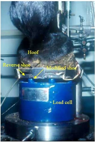
Figure 10: A photograph showing the position of the hoof, polystyrene pad and the pressure film on the load cell, after the total load was applied to the limb.
Data Acquisition
A total of four experiments were done on each limb. These included:
- Collection of reference data on partially removed (distal third) hoof wall, shod with reverse shoe,
- Collection of data on partially removed (distal third) hoof wall, shod with reverse shoe and an unwedged polystyrene pad,
- Collection of data on partially removed (distal third) hoof wall, shod with a reverse shoe and a 66% wedged polystyrene pad,
- Collection of data on partially removed (distal third) hoof wall, shod with a reverse shoe and a 50% wedged polystyrene pad.
The data for the pressure distribution in the four quadrants from the pressure films were calculated by using the SigmaScan (Image Measurement Software, USA) & Sigma ScanPro computer programmes (Automated Image Analysis Software) (Jandel Scientific Software, USA). The footprint on the pressure film was scanned into a computer file and converted to a greyscale picture. This picture was imported to the SigmaScan programme for further analysis. Reference data of the pressure per colour was obtained by converting the film manufacturer’s colour calibration chart to a greyscale and then calculating the intensity of each colour on the testing strip. The footprints were then loaded into the SigmaScan programme as greyscale. The intensity of the footprint was then calculated using the “annotation to determine average intensity across a grid” procedure of SigmaScan Pro. This procedure works on the principle that a grid is drawn on an image. The average intensity of the pixels under the grid is measured. The average intensity is measured by calculating the sum of the grey level values of all pixels in a given object, divided by the total number of pixels in that object. The images in this experiment were uncalibrated and therefore, a value of 0 was full black and a value of 255 was full white. Each footprint was then divided into four quadrants with the line of the frog as a medial/lateral division, and a line halfway between the toe and the heels as a division between the dorsal and palmar halves (Figure 11). The mean value of each quadrant was then calculated using the SigmaPlot (Jandel Scientific software, USA) programme.
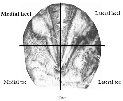
Figure 11: Division of the pressure film into four quadrants, starting at the medial heel area and working clockwise for a right front limb, and anti-clockwise for a left front limb.
4.2.3 Data Analysis
Statistical evaluation of the data was done with the aid of computer software (SigmaStat Statistical Software, Jandel Scientific Software, USA). The effect of the reverse shoe, without a polystyrene pad and then with 100%, 66% and 50% wedged pads were investigated using a One-Way Repeated Measures Analysis of Variance, and Tukey’s Test was used to investigate differences between specific treatments which are summarised in Table 4. The effect of loads on the four solar quadrants for the three different wedges was investigated, using a Two-Way Analysis of Variance (ANOVA), and Tukey’s Test was used to investigate differences between specific treatments (Appendix D). For all the statistical interpretations, the significance level was set at p<0.05.
4.3 Results
The bodyweights of the three horses used in this study were 423kg (horse 1), 506 kg (horse 2) and 430kg (horse 3), respectively. The loads used during the experimental procedures were approximately 66% of the measured bodyweight of each horse and were calculated as 2.750 kN for horse 1, 3.330 kN for horse 2 and 2.930 kN or horse 3.
The geometrical measurements taken from the radiographs in the in vitro study done on six cadaver limbs to test the effect of a reverse shoe and polystyrene pads on the load-bearing of the sole and the hoof wall of a hoof as well as the corrected values for the measurements are presented in Table 1. Table 2 is a summary of the temperature and relative humidity measured during the experimental procedure. These measurements were necessary in order to choose the appropriate curve to be used for the calculations of the pressures as indicated on the pressure film.
Table 3 is a summary of the load applied to the six cadaver limbs during the in vitro study and the load measured by the two load cells. The data obtained from the load cells included the load borne by the polystyrene pad and the total load. The load borne by the hoof wall was then calculated by subtracting the load borne by the polystyrene from the total load measured.
The means of the load-bearing of the reverse shoe (hoof wall), the solar surface and the total load applied to the limb are shown in Figure 12. This figure includes the means for all four treatments. These treatments include no use of a polystyrene solar pad, a pad with a 50% wedge, one with a 66% wedge and lastly a polystyrene pad with no wedging. Figure 13 shows the pressure distribution in the four quadrants of the solar surface of the hoof for the three different wedges of polystyrene pads. The three pads used included one with no wedging, a 66% wedge and a 50% wedge.
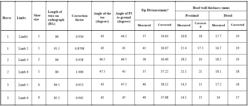
Table 1: Geometrical measurements taken from the radiographs and corrected with the correction factor for the in vitro study done on six cadaver limbs to test the effect of a reverse shoe and polystyrene pads on the load-bearing of the sole and the hoof wall of hooves. *Distance from the toe of the dorsal hoof wall to the distal dorsal tip of P3 (mm)
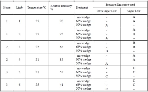
Table 2: Summary of the temperature and relative humidity recorded during the in vitro study done on six cadaver limbs for the analysis of the pressure film. The pressure film curves used to calculate the pressure applied to the film are sensitive to temperature and humidity changes, and the three symbols are indications of the curves used under specific conditions.
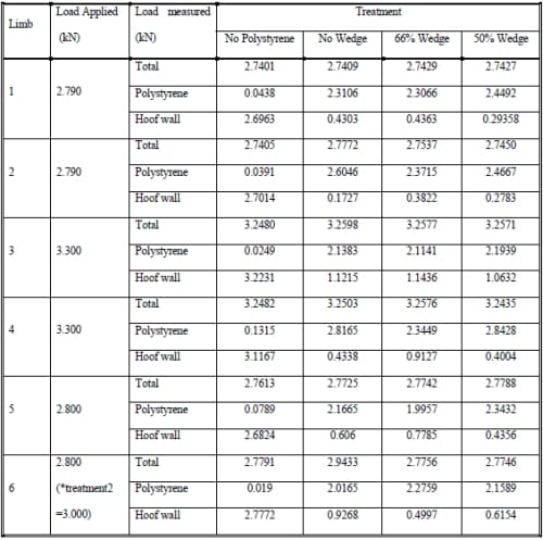
Table 3: Load applied and load borne by the polystyrene pad, the hoof wall and total load measured in an in vitro study done on six cadaver limbs. * The load applied to limb 6 during treatment 2 was 3 kN. This was due to an operational error where the Tensile Testing machine was not stopped at 2.8 kN as required.
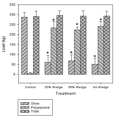
Figure 12: Mean of the loads recorded for the load borne by the reverse shoe (the hoof wall), the polystyrene pad (sole) and the total load applied to the six limbs during an in vitro study done on cadaver limbs. * Significantly different from control.

Figure 13: Pressure distribution in the four quadrants of the solar surface area for three different wedgings of polystyrene pads. The four quadrants are defined as the area when a straight line is drawn on the line of the frog and another line is drawn perpendicular to that line at the quarters of the hooves. Mean values of quadrants with different letters were significantly different.
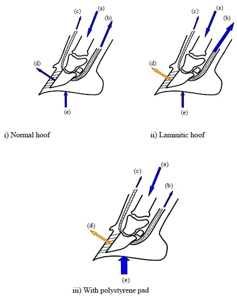
Figure 14: Diagrams of the distractive and supportive forces of P3 i) in normal hooves, ii) in laminitic hooves and iii) after the application of a polystyrene solar support. a) The downward load exerted by the weight of the horse through the bony column and distributed through the distal phalanx, b) the proximal-palmar pull of the deep digital flexor tendon from its insertion on the flexor surface of P3, c) the pulling force of the common digital extensor tendon, d) the lamellar attachment between P3 and the hoof wall and e) the distal phalangeal supportive function of the sole and frog. (These diagrams and forces are not to scale.).
4.4 Discussion
Normal hooves
This study investigated the effect of a reverse shoe with polystyrene padding and partial dorsal hoof wall removal on the biomechanics of the hoof. The feet of horses with chronic laminitis do not exhibit identical pathological changes; therefore a study of normal feet should precede any studies on feet with chronic laminitis to obtain normal data to which later studies can be compared. The forelimbs of the horses were used in this study, because laminitis is more likely to occur in the hooves of these limbs. From the results obtained from the radiographs, it was shown that the hooves used in this study were all normal. The normal hoof wall thickness for most breeds varies between 15 to 18mm. A dorsal hoof wall thickness of 20mm and more may be the result of thickening of the soft tissues that may be caused by laminitis40. The mean hoof wall thickness for all the hooves used in this study was less than 20 mm (Table 1).
The phalanges in all the feet used in this study were in a straight line and the dorsal surfaces of the pedal bones of the different hooves were parallel to the dorsal surface of the hoof wall. In laminitic cases the pedal bone starts to move distally and rotates within the hoof, causing a break in the digital axis. There is also a loss of parallelism between the dorsal surface of the pedal bone and the dorsal surface of the hoof wall20. The angle of P3 to the ground surface, for Thoroughbred horses, was shown by PJ Cripps and RA Eustace to have a mean value of 47.6 degrees, with a standard deviation of 2.0915. Accordingly to Table 1, the angles of P3 to the ground surface for all the hooves used in this study were within these criteria.
The distractive and supportive forces of P3, as indicated in Figure 14, change between normal hooves, laminitic cases and after the application of polystyrene pads. In laminitic cases, the stabilising or supportive force, due to the lamellar attachment between P3 and the hoof wall, is decreased or lost. This is a very important force, because the horse is actually hanging in the hoof by these lamellar attachments. The loss of this supportive force can result in rotation of P3 as a result of the tension in the deep digital flexor tendon (DDFT), and in more severe cases, a sinking of P3 takes place due to the weight of the horse. The pulling force of the common digital extensor tendon cannot compensate for the DDFT force, and this imbalance may result in the rotation of P3 towards the pulling force of the DDFT52. When a polystyrene pad is applied to the hoof, the forces acting on P3 change. The polystyrene compensates for the lost in lamellar force by supporting P3. By filling the entire underfoot surface, the pad minimises the possibility of displacement.
Load borne by hoof wall and solar pad
The solar surface area comprises 53.39% of the entire underfoot surface implying indicates that a solar pad can relieve some of the load-bearing of the hoof wall. Figure 12 indicates that the polystyrene pads do have a significant influence on the distribution of load-bearing between the hoof wall and the solar surface. Approximately 79% of the total load was borne by the solar surface. Many researchers have documented the value of solar support in the treatment of laminitis. Frog support helps stabilise and support P3. This stability and support may decrease the strain on the compromised lamellae and reduce pain. In a study done on the reverse even frog pressure shoe, it was shown that an increased frog pressure decreases the weight-bearing on the hoof wall and therefore releases strain on the compromised lamellae62. The non-adjustable and adjustable heart-bar shoes also provide constant solar support. The adjustable heart-bar shoe is more beneficial than the non-adjustable shoe because the frog support given by the solar plate can be adjusted as the hoof grows20,25 or displacement continuous.
The heart-bar shoe is difficult to apply to the hoof. The wrong placement of the frog support may cause further damage to the sensitive tissues of the sole. It is also difficult to estimate the optimum pressure that has to be applied to the sole by using the heart-bar shoe. With the adjustable heart-bar shoe, this problem can be minimised, but it also may cause further damage if not applied correctly. Other disadvantages of the adjustable heart-bar shoe is the possibility that the thread of the Allen screw may be damaged during the application of the shoe, and the shoe may have to be removed and replaced. Abscesses can also occur under the frog due to the pressure27. The polystyrene pad applied for solar support is more beneficial than the heart-bar or the reverse even frog pressure shoe, because the pad can be fitted to the hoof without difficulty. The pressure is distributed over the whole solar surface and is not concentrated on the frog only. Polystyrene is also a soft material which could minimise solar necrosis. For significant solar support, polystyrene pads proved to be a good approach.
Load-distribution for different wedged pads
There was no difference in the load-distribution between the shoe area and the solar area for the three different treatments. The total load applied to the limb during the experiments was higher than the compression yield strength of the polystyrene pads used in this study. The pads compressed and deformed according to the solar area, regardless of the wedging of the polystyrene pad. A further explanation for the apparent lack of differences between the different treatments, may also be the cutting off of the excess polystyrene that protruded underneath the shoe after compression, especially for the no-wedged polystyrene pad. The excess material destabilised the reverse shoe on the measuring apparatus and caused inaccurate measuring of the load applied to the solar area.
Pressure distribution on the solar surface
The pressure film used in this study gave an indication of the pressure distribution on the solar surface of the hoof. Table 2 presents the temperatures and humidity values measured during the tests. This information was important for calculating the correction factor for the pressure film. Figure 13 indicates the effect of the difference wedges of the polystyrene pads. There was a s
ignificant difference between the load-bearing of the medial and lateral heel area on the one hand, and the medial and lateral toe on the other hand. No significant differences were found between the loads measured between the medial heel and lateral heel or for the medial toe and lateral toe areas. The three different treatments showed no significant differences. For all three treatments, the pressure distribution was approximately 60% of the total pressure carried by the palmar half and 40% by the dorsal half of the solar surface. Therefore, a greater load was borne by the heels than by the toe area of the sole. This distribution is very important for the minimisation of damage to the blood vessels which wrap around the dorsal end of P3.
The damaged lamellae in the laminitic hoof cause abnormal loading of the remaining lamellae. A reverse shoe compensates for the abnormal load bearing in the damaged area by shifting the load more towards the palmar surface of the hoof. Application of the reverse shoe alone is not sufficient, because the total load has to be carried by the hoof wall.
Colahan et al.10,11, found in both their studies that the centre of pressure was located in the medial heel area. In their study, they used a cassette made from plywood and Plexiglas and applied a load of 200kg to the hoof for 2 minutes. They measured the load-distribution on the whole underfoot surface. From the results shown in Figure 13, the load was distributed evenly in the heel area. An explanation for the differences between the present study and the study of Colahan et al, could be the use of different types of material in the studies. In the present study, pressure distribution for the solar area was evaluated, while Colahan et al, investigated the total underfoot area. The differences in load, applied to the hooves (270 – 330 kg in the present study, and 200kg in the study of Colahan et al) and the time that the loads were applied to the limbs (20 seconds in the present study, and 2 minutes in the study of Colahan et al) may also have influenced the results. Both studies agree that the heel area bears more weight than the toe area. This is therefore an indication that with the application of the polystyrene pad, the load at the toe area in a laminitic case will be less and will be shifted to the less severely damaged heel area of the foot. The load of the polystyrene pad on the solar surface is distributed over the whole solar surface and not on the frog alone. This approach is therefore an improvement on the nonadjustable and the adjustable heart-bar shoes25,27 and the reverse even frog pressure shoe42. For this approach, it is only necessary to replace the pad and not the reverse shoe, for at least the first four to five weeks (This is based on observations made from clinical cases). This gives the hoof time to heal and the hoof wall will not be damaged by the frequent replacement of the shoe as in the case of the heart-bar shoe27.
4.5 Conclusions
This study indicates that the application of the reverse shoe with polystyrene padding does have a beneficial effect on the biomechanics of the hoof of a normal horse. The first conclusion is that the polystyrene pad creates a load shift in the normal hoof. The second conclusion is that most of the load applied to the hoof is now carried by the solar area, and especially by the palmar half of the solar surface.
Because of the even distribution of the pressure on the solar surface, the treatment as described in this study, is more advantageous than the reverse even frog pressure shoe or the heart-bar shoe. By applying the polystyrene pad, load-bearing at the dorsal half of the hoof wall is decreased and further tissue damage is minimised.
The pressure concentration on the palmar half of the sole may minimise the negative effect on the blood supply to the sole. The characteristics of the polystyrene make it a very useful material for solar padding. Its compressibility, without becoming rigid, prevents the development of solar necrosis. The polystyrene also deforms and fills the whole solar surface which enlarges the weight-bearing area. The results of this study must not be seen to be the ultimate treatment in all cases of laminitis, but merely as another step in the approach to counteracting this dreadful condition.
Chapter 5 – Investigation into the In Vivo Effect of a Reverse Shoe and Polystyrene Padding on the Biomechanics of the Front Hoof of the Horse
5.1 Introduction
Throughout the years, many attempts have been made to address the problems of laminitis. The heartbar shoe, reverse even frog pressure shoe and different types of solar padding were some of the attempts to address this problem22,28,42,64,66.
The reverse shoe together with polystyrene padding, with a thickness of 60mm, density of 32kg/m3 and wedge of 50% as a treatment for laminitis, has been proved to be very promising in clinical cases of laminitis treated at the Veterinary Academic Hospital, Faculty of Veterinary Science, Onderstepoort. Directly after application of the polystyrene pads, most horses appear to be much more comfortable and willing to stand and even bear weight on the affected hooves. Questions arising from this approach include: a) whether the density of the polystyrene pads is sufficient, and b) what happens to the load distribution between the polystyrene and the hoof wall over a period of time due to the compression of the polystyrene pads.
In the previous study done on cadaver limbs it was shown that the polystyrene padding and reverse shoe combination does have an influence on the load distribution between the hoof wall and the solar surface of the hoof. Further research was necessary to investigate the effect of different densities and different thicknesses of polystyrene padding on the load distribution between the solar surface and the hoof wall and also to determine the extent of compression of the polystyrene over a period of time and the effect thereof on the load distribution.
The aim of this study was threefold. Firstly, to investigate the effect of the reverse shoe and different densities of polystyrene used as solar support on the load distribution on the front hooves of live horses, secondly, to investigate the effect of the reverse shoe and different thicknesses of polystyrene solar pads on the load distribution on the front hooves of live horses, and thirdly, to measure the effect of the compression of the polystyrene over time on the load distribution. Polystyrene with densities of 32kg/m3, 24kg/m3 and 16kg/m3 were used in the study. The wedging of all the polystyrene pads used in this study was 50%. The thicknesses of each set of polystyrene pads with different densities, were 100mm and 60mm respectively. The load carried by the hoof wall and the solar area was measured separately using two load cells and a purpose-designed solar plate.
5.2 Materials and Methods
Three Thoroughbred horses were used in this study. These horses were from the group of animals that belong to the Equine Research Centre, Faculty of Veterinary Science, Onderstepoort and had no history of laminitis, lameness or any other abnormalities in the front limbs, or radiographical pathology. The horses chosen had number 0 or 1 shoe sizes in order to simplify the measurements.
5.2.1 Experimental Design
For the purpose of this study, three horses were used and, therefore, a total of six front limbs. The bodyweight of each horse and the shoe size of each front limb were recorded (Table 5). A total of six different treatments were performed on each front limb (Table 6). The order in which the three horses were tested, as well as the order in which the six treatments were done on each horse, were randomised.
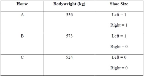
Table 4: Bodyweight and shoe sizes of the six limbs, as recorded for the three horses used in this study.
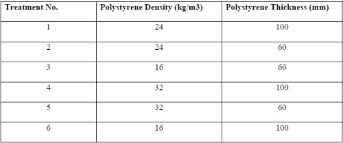
Table 5: Description of the different treatments used in this study. The different densities of the polystyrene pads were 32kg/m3, 24kg/m3 and 16kg/m3 and the two different thicknesses 100mm and 60mm.
The computer system for the data collection consisted of two calibrated load cells (Route, Rulp 5 ton, serial number 11716, Load Cell Services, 1 ton, serial number 29560), amplifier (HBN Signal Conditioner, Germany), a portable data recording unit (Diagnostic Instrument, FFT Analyser, Model: PL202), a modified horse shoe and a solar plate. One load cell measured the total load applied by the system to the front limb and a second cell measured the load exerted on the polystyrene pad. The load cells were buried in the ground to ensure that the horse would stand on a surface level with the ground when standing on the cells (Figure 15).
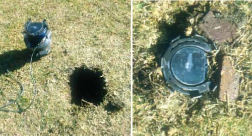
Figure 15: Load cells were buried in a hole, with only the modified shoe and the solar plate visible above the ground. The horse stood on a level surface when one of its limbs was on the test apparatus.
For each limb, the polystyrene as indicated in Table 6, with a wedge of 50%, was prepared. The front hooves of the three horses were trimmed to a point of latero-medial and toe-heel balance. No dorsal hoof wall removal was performed during the in vivo study. A number 0 or 1 reverse shoe was applied to each hoof and the body mass of the horse was recorded.
In the beginning of the experiments, reference data were recorded for both front limbs of each of the three horses respectively. For the reference data, the limbs were shod with reverse shoes, but no polystyrene pads were applied to the soles. The horse stepped with one limb onto the load cells. An assistant lifted the other front limb off the ground. When the horse was standing comfortably, data recording started. The assistant put the foot down and the limb from which data were recorded was lifted and put down onto the load cell again. The other limb was lifted again. Three sets of data were recorded. Recording time was 4 seconds with a frequency of 50Hz. The average of these data was taken as the reading for the specific measurement. The horse stepped off the load cells and reference data for the other limb were recorded. After the reference data were recorded, the first of the polystyrene pads was applied to the hoof according to the randomised order as described earlier. The horse then stepped onto the load cells again and the whole procedure was repeated. After data recording, another polystyrene pad was applied to the other hoof and data were recorded for that limb. Between the next measurements, the horse was walked for 5 minute periods on a concrete surface to compress the polystyrene. A total of 5 measurements was recorded for each limb: 1) reference data, 2) directly after applying pads, 3) 5 minutes, 4) 10 minutes and 5) 15 minutes after walking on a concrete surface. The polystyrene pad was changed according to the randomised order and the whole experimental procedure was repeated for the new set of polystyrene pads. This procedure was followed until all six the different treatments had been applied. The same experimental procedure was repeated for the other two horses according to the randomised order.
5.2.2 Data Analysis
Only the loads from the two load cells for the different treatments per limb were recorded. The data were downloaded to a computer and data analysis was done with the aid of Matlab (Appendix C) and Sigmaplot Computer Programmes.
Statistical evaluation of the data was done with the aid of computer software (SigmaStat Statistical Software, Jandel Scientific Software). The effects on loads at the four time intervals were investigated using a Two-Way Repeated Measures Analysis of Variance (ANOVA). Tukey’s Test for Pairwise Multiple Comparison Procedures was used to investigate differences between specific treatments (Appendix E). For all the statistical interpretations, significance was set at p<0.05.
5.3 Results
Figure 16 shows a comparison of the load-bearing over time of the polystyrene pads with a thickness of 60mm and densities of 16kg/m3, 24kg/m3 and 32kg/m3, respectively. All three different pads had high initial load values that decreased as time increased. Significant differences were found between treatments for time intervals 0, 5 and 10 minutes, but after 15 minutes, no significant differences could be found between the different pads.
The comparison of the load-bearing over time for three polystyrene pads with a thickness of 100mm and densities of 16kg/m3, 24kg/m3 and 32kg/m3, respectively is shown in Figure 17. For the thickness of 100mm, no significant differences could be found between the treatments for the four different time periods.
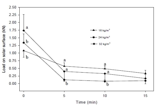
Figure 16: Load on the solar surface for polystyrene pads with different densities (24 kg/m3, σ 16kg/m3 and 32kg/m3) and the same thickness of 60mm. Mean values of time indicated by different letters, are significantly different.
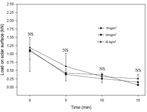
Figure 17: Load on the solar surface for polystyrene pads with different densities (24 kg/m3, σ 16kg/m3 and 32kg/m3) and the same thickness of 100mm. NS: No significant difference.
5.4 Discussion
From the previous study in Chapter 4, it was clear that polystyrene padding does have a significant influence on the load borne by the solar surface and the hoof wall when the hoof is shod with a reverse shoe and polystyrene padding is applied to the sole. The effect of polystyrene with different thicknesses and different densities on the load borne by the solar surface needed to be investigated. Figures 16 indicates that the 32kg/m3 x 60mm polystyrene pad bore a significantly higher load during the initial recording. There were no significant differences between the other treatments at this point. After 5- and 10- minute periods, the loads borne by the solar area for the 16kg/m3 x 60mm and the 32kg/m3 x 60mm pads were significantly higher than that for the 24kg/m3 x 60mm pad. Whilst significant differences were observed between the load born by the polystyrene pads of different densities during the first 10 minutes after application, no significant differences were present at 15 minutes after application. As no trend was discernible between the different densities of polystyrene during the compression phase, the mechanism determing these observed differences could not be determined.
When the effect of polystyrene with a thickness of 100mm and densities of 32kg/m3, 24kg/m3 and 16kg/m3 on the load distribution on the solar surface were investigated, as presented in Figure 17, no significant differences could be found between any of the treatments. The same tendency as for the 60mm thickness polystyrene was observed, in that the initial load was high and then faded down in a hyperbolic curve. The loads borne by the polystyrene pads with a thickness of 100mm, were lower than for those of 60mm. This is the complete opposite of what
was expected, but it was found that after compression, some of the 100mm thick polystyrene curled underneath the reverse shoe, thus causing a partial loss of solar support and solar load-bearing. The excess polystyrene underneath the shoe was removed to ensure proper fitting of the reverse shoe onto the modified shoe of the recording apparatus.
Due to the sensitivity of the laminitic hoof, the working time on the hoof had to be limited. It is therefore not recommended that the polystyrene with a thickness of 100mm be used in the treatment of laminitis. The protrusion of the excess amount of polystyrene underneath the shoe may cause instability of the hoof and may therefore cause further damage to the compromised lamellae
For the initial 10 minutes, the 32kg/m3 x 60mm and 16kg/m3 x 60mm pads bore the most solar load. After 15 minutes, there was no difference in the load-bearing between the treatments. It will be necessary to investigate the long-term effect of all three solar pads on the solar load-bearing. The 15- minute period was too short. The long-term effect of all three pads on the solar blood flow also needs to be investigated. Walking on the pad might also have an effect on the efficiency of the solar pads.
5.5 Conclusion
In order to obtain the best solar support with a polystyrene pad, it was necessary to investigate the effect of different densities and thicknesses of polystyrene. It is important to note that the results gained from this study are only valid for a horse with a bodyweight of approximately 551kg.
It was not very clear from the results of this study which type of polystyrene will provide the best solar support. All the solar pads showed a hyperbolic tendency in which the initial load was high and then was reduced with time. From the observations made during the experimental procedure, the 32kg/m3 x 60mm pad compressed to a more dense and rigid end-product than the 16kg/m3 x 60mm pad which correlates with the modulus of elasticity of the material used in the study. The residue elasticity of the 16kg/m3 x 60mm pad may be a positive property for reducing compression on the blood flow underneath P3. This can be compared to a person walking in shoes with soft soles as opposed to ones with harder soles. It was concluded that polystyrene pads with densities of 32kg/m3, 24kg/m3 and 16kg/m3 and thicknesses of 100mm and 60mm would prove similar support for the remainder of the period that they were applied follow a variable compression phase of less than 15 minutes. Further research need to be done to investigate the effect of the polystyrene pad on the solar surface for a longer period.
The 100mm thick polystyrene pads were very uncomfortable for the horse. The thickness and the wedging of 50% raised the heels very high and could cause further damage to the affected lamellae as the horse was actually standing on its toes for the first few seconds, until the polystyrene was significantly compressed. The polystyrene that protruded underneath the reverse shoe also constituted waste of useful material. Polystyrene pads of 100mm thick are therefore not recommended for treatment of laminitis.
Chapter 6 – General Conclusions
The following conclusions were drawn from this study:
- The reverse shoe applied together with polystyrene padding does have an effect on the biomechanics of the hoof of a normal horse.
- The polystyrene pad causes a load shift in the normal hoof. The load on the hoof wall was relieved and a greater load was borne by the solar surface after the application of the solar pad.
- From the in vitro study it became clear that the polystyrene-padded solar area carried most of the load applied to the hoof.
- The pressure-sensitive film indicated that the palmar half of the solar surface carried a greater load than the dorsal half of the solar surface, when a polystyrene pad was applied to the hoof. The loadbearing at the dorsal half of the hoof wall was decreased which could minimise further tissue damage. The pressure concentration on the palmar half of the sole could minimise the negative effect on the blood supply.
- By using polystyrene as a solar pad, P3 is stabilised and further rotation of P3 may be minimised
- No suggestions can be made about the optimum wedging of the polystyrene pad to give the optimum solar support.
- The characteristics of the polystyrene make it a very useful material for solar padding. Its compressibility, without becoming rigid, may minimise the possibility of solar necrosis.
- The polystyrene also deforms to fill the whole of the solar surface, thereby enlarging the weightbearing surface.
- Use of the reverse shoe, together with polystyrene pads and partial dorsal hoof wall removal, promises to be a very useful treatment for laminitic cases.
- The 16kg/m3 x 60mm pads remained more elastic than any of the others after a time period of 15 minutes, due to their lower modulus of compression. This characteristic may be beneficial, as care needs to be taken to prevent further injury of the blood vessels.
- Polystyrene with a thickness of 100mm is not suitable for use in solar pads as it is uncomfortable for the horse, and too much of the polystyrene curls underneath the reverse shoe.
- The reverse shoe and polystyrene combination as a treatment for laminitis is an improvement on the reverse even frog pressure technique and the adjustable heart-bar shoe, because the pressure distribution is more even over the solar surface and is not concentrated on the frog as is the case with the other two treatments.
- The reverse shoe does not have to be replaced as often as the heart-bar shoe and therefore less damage is caused to the hoof wall due to replacement of the shoe.
- The use of polystyrene as a solar pad is more advantageous than other padding materials, as it is easy to change the polystyrene pad without removing the shoe.
- Polystyrene solar pads are very economical.
Chapter 7 – Further Recommendations
The following research projects are all suggested for further study in the refinement of the use of the reverse shoe and polystyrene pad on laminitic horses.
Engineering research
- Designing a computerised model of the hoof and simulating the effect of the reverse shoe and polystyrene padding on this model.
- The computer programme may be applied to investigate the effect of dorsal hoof wall removal on the biomechanics of the hoof wall, and the role of the reverse shoe and polystyrene padding on the hoof biomechanics.
- More research needs to be done on laminitic cases. The procedures described in this dissertation can be applied to laminitic hooves and the results compared with the results obtained in this study.
- Research needs to be done on a technique to measure the movement of P3 in relation to the hoof wall in laminitic cases after the application of the reverse shoe and the polystyrene padding.
- The effect of the polystyrene needs to be investigated over a longer period of time. This will give a better indication of the “life time” of the polystyrene pad in order to be the most effective.
- The optimum thickness of the 16kg/m3 polystyrene pad for a horse with a body mass of 551kg needs to be investigated.
- The optimum density and thickness of polystyrene pads for horses with different body weights need to be ascertained.
- Research must be done to find material more suitable than polystyrene for use as solar pads.
- The effect of the reverse shoe and polystyrene pads on the blood-flow to the solar surface of the hoof.
- The effect of using a polystyrene pad on the total solar surface, without shoei
ng the horse with acute and chronic laminitis. - The positioning of the reverse shoe in relation to the distal dorsal tip of P3.
Farriery
- Using polystyrene pads in conjunction with glue-on or other types of corrective shoeing.
- The correct application of the reverse shoe to the hoof in order to ascertain the maximum support.
Appendix A: Figures Illustrating the Compressive Strength of Polystyrene Supplied By the Manufacturer
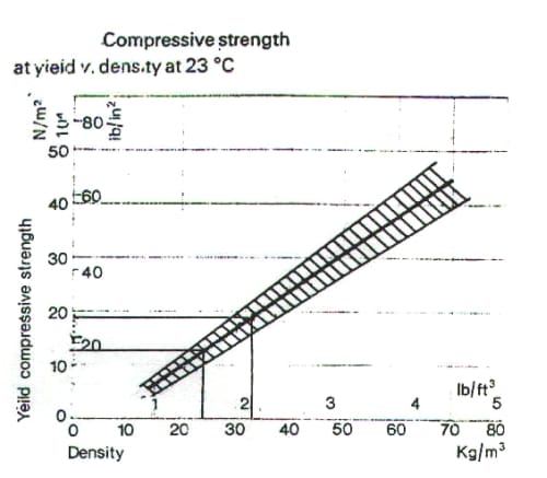
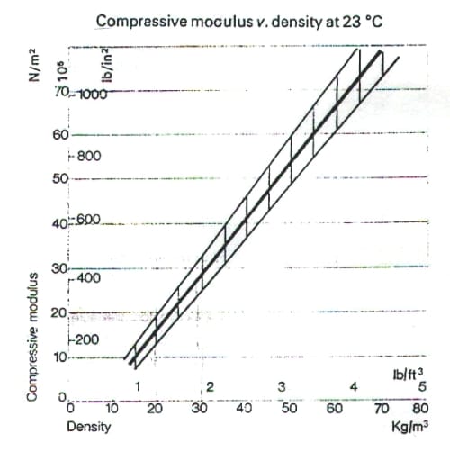
Appendix B: Standard Continuous Pressure Chart and Graph of Temperature and Humidity Conditions Used for the Analysis of the Data of the Pressure Films
Ultra Super Low Film
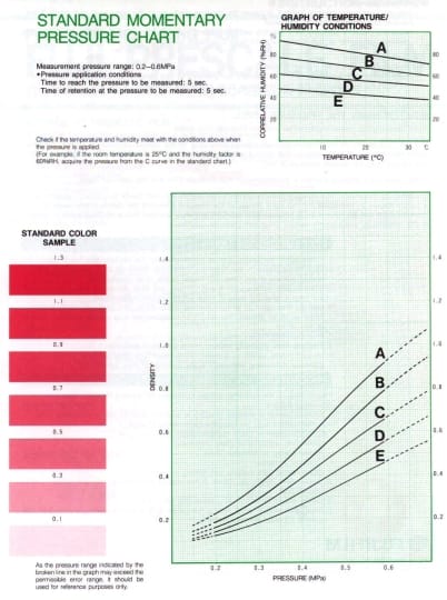
Super Low Film
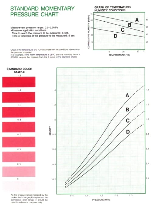
Appendix C: Outline of Computer Program
clear all close all
% This program calculate the load-bearing of the polystyrene and the
% total hoof respectively. Channel a is the total load and b is the
% load carried by the polystyrene.
% L = Left fore limb, R = Right fore limb.
% Henning Mostert
% Equine Research Centre Onderstepoort. 26/9/2000
%Total Load
%Left fore
load tst66a.txt
lip66a=tst66a(1:length(tst66a)-1,:);
save lip66a lip66a
lip66acl(:,1)=lip66a(:,1)*(-100*9.81);
% Data multiplied with the calibration factor for the load cell. 20V = 5t
% with multification factor of 0.5)
lip66acf = filt(lip66acl,’L’,5,63);
save lip66acf lip66acf
t=time(lip66acf,67);
lip66pol = polyfit(t,lip66acf(:,1),2);
% Calculate the polynomal function for the specific data;
save lip66pol lip66pol;
lip66fig = polyval(lip66pol,t);
% Create a plot with the specified polymere coeficients;
% 2nd data recording of same test
load tst67a.txt
lip67a=tst67a(1:length(tst67a)-1,:);
save lip67a lip67a;
lip67acl(:,1)=lip67a(:,1)*(-100*9.81);
lip67acf = filt(lip67acl,’L’,5,63);
save lip67acf lip67acf;
t=time(lip67acf,67);
lip67pol = polyfit(t,lip67acf(:,1),2);
save lip67pol lip67pol;
lip67fig = polyval(lip67pol,t);
% 3nd data recording of same test
load tst68a.txt
lip68a=tst68a(1:length(tst68a)-1,:);
save lip68a lip68a;
lip68acl(:,1)=lip68a(:,1)*(-100*9.81);
lip68acf = filt(lip68acl,’L’,5,63);
save lip68acf lip68acf;
t=time(lip68acf,67);
lip68pol = polyfit(t,lip68acf(:,1),2);
save lip68pol lip68pol;
lip68fig = polyval(lip68pol,t);
% Create a graft for the data;
plot(t,[lip66acf(:,1),lip67acf(:,1),lip68acf(:,1)]),title(‘Horse B 24/100 Polys.
Total’),xlabel(‘Time(sec)’),ylabel(‘N’)
pause
plot(t,[lip66fig,lip67fig,lip68fig]),title(‘Horse B 24/100 Polys. Total : Curve
fit.’),xlabel(‘Time(sec)’),ylabel(‘N’)
pause
lip66acfmean=mean(lip66acf(:,1));
lip67acfmean=mean(lip67acf(:,1));
lip68acfmean=mean(lip68acf(:,1));
lip66figmean=mean(lip66fig(:,1));
lip67figmean=mean(lip67fig(:,1));
lip68figmean=mean(lip68fig(:,1));
% Calculate the mean for all three sets of data and the curve fit;
lip12lamean = (lip66acfmean+lip67acfmean+lip68acfmean)/3
pause
lip12lpmean = (lip66figmean+lip67figmean+lip68figmean)/3
pause
clear lip66a lip66acl lip66acf
clear lip67a lip67acl lip67acf
clear lip68a lip68acl lip68acf
pause
%Load carried by polystyrene
%Left Fore
load tst66b.txt
lip66b=tst66b(1:length(tst66b)-1,:);
save lip66b lip66b
lip66bcl(:,1)=lip66b(:,1)*(-250/2)*9.81;
% Data multiplied with the calibration factor for the load cell. 20V = 5t with multification factor of
0.5)
lip66bcf = filt(lip66bcl,’L’,5,63);
save lip66bcf lip66bcf
t=time(lip66bcf,67);
% Calculate poli24/100mal cuve fitting;
lip66bpo = polyfit(t,lip66bcf(:,1),2);
save lip66bpo lip66bpo;
% Apply calculated polynomal function to data;
lip66bfi = polyval(lip66bpo,t);
%plot(t,(lip66bcf(:,1))),title(‘lipgo 24/100 Polys. Total’),xlabel(‘Time(sec)’),ylabel(‘N’)
% 2nd data recording of same test
load tst67b.txt
lip67b=tst67b(1:length(tst67b)-1,:);
save lip67b lip67b;
lip67bcl(:,1)=lip67b(:,1)*(-250/2)*9.81;
% Data multiplied with the calibration factor for the load cell. 20V = 5t with multification factor of
0.5)
lip67bcf = filt(lip67bcl,’L’,5,63);
save lip67bcf lip67bcf;
t=time(lip67bcf,67);
lip67bpo = polyfit(t,lip67bcf(:,1),2);
save lip67bpo lip67bpo;
lip67bfi = polyval(lip67bpo,t);
%plot(t,(lip67bcf(:,1))),title(‘lipgo 24/100 Polys. Total’),xlabel(‘Time(sec)’),ylabel(‘N’)
% 3nd data recording of same test
load tst68b.txt
lip68b=tst68b(1:length(tst68b)-1,:);
save lip68b lip68b;
lip68bcl(:,1)=lip68b(:,1)*(-250/2)*9.81;
% Dbta multiplied with the calibration factor for the load cell. 20V = 5t with multification factor of 0.5)
lip68bcf = filt(lip68bcl,’L’,5,63);
save lip68bcf lip68bcf;
t=time(lip68bcf,67);
lip68bpo = polyfit(t,lip68bcf(:,1),2);
save lip68bpo lip68bpo;
lip68bfi = polyval(lip68bpo,t);
plot(t,[lip66bcf(:,1),lip67bcf(:,1),lip68bcf(:,1)]),title(‘Horse B 24/100 Polys. Solar
surface’),xlabel(‘Time(sec)’),ylabel(‘N’)
pause
plot(t,[lip66bfi,lip67bfi,lip68bfi]),title(‘Horse B 24/100 Polys. Solar surface : Curve
Fitting’),xlabel(‘Time(sec)’),ylabel(‘N’)
pause
lip66bcfmean=mean(lip66bcf(:,1));
lip67bcfmean=mean(lip67bcf(:,1));
lip68bcfmean=mean(lip68bcf(:,1));
lip12lbmean = (lip66bcfmean+lip67bcfmean+lip68bcfmean)/3
clear lip66b lip66bcl lip66bcf
clear lip67b lip67bcl lip67bcf
clear lip68b lip68bcl lip68bcf
pause
% Total load
% Right Fore
load tst63a.txt
lip63a=tst63a(1:length(tst63a)-1,:);
save lip63a lip63a;
lip63acl(:,1)=lip63a(:,1)*(-100*9.81);
lip63acf = filt(lip63acl,’L’,5,63);
save lip63acf lip63acf;
t=time(lip63acf,67);
lip63pol = polyfit(t,lip63acf(:,1),2);
save lip63pol lip63pol;
lip63fig = polyval(lip63pol,t);
% 2nd data recording of same test
load tst64a.txt
lip64a=tst64a(1:length(tst64a)-1,:);
save lip64a lip64a;
lip64acl(:,1)=lip64a(:,1)*(-100*9.81);
lip64acf = filt(lip64acl,’L’,5,63);
save lip64acf lip64acf;
t=time(lip64acf,67);
lip64pol = polyfit(t,lip64acf(:,1),2);
save lip64pol lip64pol;
lip64fig = polyval(lip64pol,t);
% 3nd data recording of same test
load tst65a.txt
lip65a=tst65a(1:length(tst65a)-1,:);
save lip65a lip65a;
lip65acl(:,1)=lip65a(:,1)*(-100*9.81);
lip65acf = filt(lip65acl,’L’,5,63);
save lip65acf lip65acf;
t=time(lip65acf,67);
lip65pol = polyfit(t,lip65acf(:,1),2);
save lip65pol lip65pol;
lip65fig = polyval(lip65pol,t);
plot(t,[lip63acf(:,1),lip64acf(:,1),lip65acf(:,1)]),title(‘Horse B 24/100 Polys. Total-
Right’),xlabel(‘Time(sec)’),ylabel(‘N’)
pause
plot(t,[lip63fig,lip64fig,lip65fig]),title(‘Horse B 24/100 Polys. Total-Right: Curve
Fitting’),xlabel(‘Time(sec)’),ylabel(‘N’)
pause
lip63acfmean=mean(lip63acf(:,1));
lip64acfmean=mean(lip64acf(:,1));
lip65acfmean=mean(lip65acf(:,1));
lip12ramean = (lip63acfmean+lip64acfmean+lip65acfmean)/3
clear lip63a lip63acl lip63acf
clear lip64a lip64acl lip64acf
clear lip65a lip65acl lip65acf
pause
% Solar Surface
% Right Fore
load tst63b.txt
lip63b=tst63b(1:length(tst63b)-1,:);
save lip63b lip63b;
lip63bcl(:,1)=lip63b(:,1)*(-250/2)*9.81;
lip63bcf = filt(lip63bcl,’L’,5,63);
save lip63bcf lip63bcf;
t=time(lip63bcf,67);
lip63bpo = polyfit(t,lip63bcf(:,1),2);
save lip63bpo lip63bpo;
lip63bfi = polyval(lip63bpo,t);
% 2nd data recording of same test
load tst64b.txt
lip64b=tst64b(1:length(tst64b)-1,:);
save lip64b lip64b;
lip64bcl(:,1)=lip64b(:,1)*(-250/2)*9.81;
lip64bcf = filt(lip64bcl,’L’,5,63);
save lip64bcf lip64bcf;
t=time(lip64bcf,67);
lip64bpo = polyfit(t,lip64bcf(:,1),2);
save lip64bpo lip64bpo;
lip64bfi = polyval(lip64bpo,t);
% 3nd data recording of same test
load tst65b.txt
lip65b=tst65b(1:length(tst65b)-1,:);
save lip65b lip65b;
lip65bcl(:,1)=lip65b(:,1)*(-250/2)*9.81;
lip65bcf = filt(lip65bcl,’L’,5,63);
save lip65bcf lip65bcf;
t=time(lip65bcf,67);
lip65bpo = polyfit(t,lip65bcf(:,1),2);
save lip65bpo lip65bpo;
lip65bfi = polyval(lip65bpo,t);
plot(t,[lip64bcf(:,1),lip65bcf(:,1)]),title(‘Horse B 24/100 Polys. Right : Solar
Pad’),xlabel(‘Time(sec)’),ylabel(‘N’)
pause
%plot(t,[lip64bfi,lip65bfi]),title(‘Horse B 24/100 Polys. Right : Solar Pad : Curve
fit’),xlabel(‘Time(sec)’),ylabel(‘N’)
pause
lip63bcfmean=mean(lip63bcf(:,1));
lip64bcfmean=mean(lip64bcf(:,1));
lip65bcfmean=mean(lip65bcf(:,1));
lip12rbmean = (lip63bcfmean+lip64bcfmean+lip65bcfmean)/3
clear lip63b lip63bcl lip63bcf
clear lip64b lip64bcl lip64bcf
clear lip65b lip65bcl lip65bcf
close all
clear all
Appendix D: Statistical Results of the In Vitro Study
One Way Repeated Measures Analysis of Variance Thursday, November 30, 2000, 16:43:11
Data source: Treatment and Load borne by polystyrene
Normality Test: Passed (P = 0.122)
Equal Variance Test: Passed (P = 0.655)
The differences in the mean values among the treatment groups are greater than would be expected by chance; there is a statistically significant difference (P = <0.001). To isolate the group or groups that differ from the others use a multiple comparison procedure.
Power of performed test with alpha = 0.050: 1.000
A result of “Do Not Test” occurs for a comparison when no significant difference is found between two means that enclose that comparison. For example, if you had four means sorted in order, and found no difference between means 4 vs. 2, then you would not test 4 vs. 3 and 3 vs. 2, but still test 4 vs. 1 and 3 vs. 1 (4 vs. 3 and 3 vs. 2 are enclosed by 4 vs. 2: 4 3 2 1). Note that not testing the enclosed means is a procedural rule, and a result of Do Not Test should be treated as if there is no significant difference between the means, even though one may appear to exist.
One Way Repeated Measures Analysis of Variance Thursday, November 30, 2000, 16:44:09
Data source: Treatment and total load measured
Normality Test: Passed (P = 0.116)
Equal Variance Test: Passed (P = 0.656)
The differences in the mean values among the treatment groups are greater than would be expected by chance; there is a statistically significant difference (P = <0.001). To isolate the group or groups that differ from the others use a multiple comparison procedure.
Power of performed test with alpha = 0.050: 1.000
All Pairwise Multiple Comparison Procedures (Tukey Test):
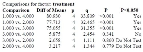
A result of “Do Not Test” occurs for a comparison when no significant difference is found between two means that enclose that comparison. For example, if you had four means sorted in order, and found no difference between means 4 vs. 2, then you would not test 4 vs. 3 and 3 vs. 2, but still test 4 vs. 1 and 3 vs. 1 (4 vs. 3 and 3 vs. 2 are enclosed by 4 vs. 2: 4 3 2 1). Note that not testing the enclosed means is a procedural rule, and a result of Do Not Test should be treated as if there is no significant difference between the means, even though one may appear to exist.
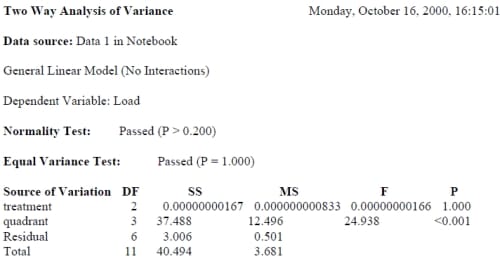
The difference in the mean values among the different levels of treatment is not great enough to exclude the possibility that the difference is just due to random sampling variability after allowing for the effects of differences in quadrant. There is not a statistically significant difference (P = 1.000).
The difference in the mean values among the different levels of quadrant is greater than would be expected by chance after allowing for effects of differences in treatment. There is a statistically significant difference (P = <0.001). To isolate which group(s) differ from the others use a multiple comparison procedure.
Power of performed test with alpha = 0.0500: for treatment : 0.0502
Power of performed test with alpha = 0.0500: for quadrant : 0.999
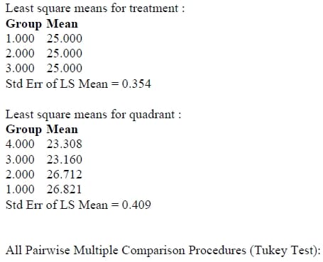
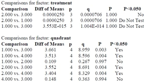
A result of “Do Not Test” occurs for a comparison when no significant difference is found between two means that enclose that comparison. For example, if you had four means sorted in order, and found no difference between means 4 vs. 2, then you would not test 4 vs. 3 and 3 vs. 2, but still test 4 vs. 1 and 3 vs. 1 (4 vs. 3 and 3 vs. 2 are enclosed by 4 vs. 2: 4 3 2 1). Note that not testing the enclosed means is a procedural rule, and a result of Do Not Test should be treated as if there is no significant difference between the means, even though one may appear to exist.
Appendix E: Statistical Results of the In Vivo Study
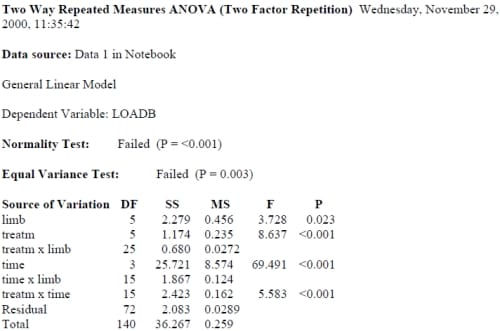
The difference in the mean values among the different levels of treatm is greater than would be expected by chance after allowing for effects of differences in time. There is a statistically significant difference (P = <0.001). To isolate which group(s) differ from the others use a multiple comparison procedure.
The difference in the mean values among the different levels of time is greater than would be expected by chance after allowing for effects of differences in treatm. There is a statistically significant difference (P = <0.001). To isolate which group(s) differ from the others use a multiple comparison procedure.
The effect of different levels of treatm depends on what level of time is present. There is a statistically significant interaction between treatm and time. (P = <0.001)
Power of performed test with alpha = 0.0500: for treatm : 0.997 Power of performed test with alpha = 0.0500: for time : 1.000 Power of performed test with alpha = 0.0500: for treatm x time : 1.000
Expected Mean Squares: Approximate DF Residual for treatm = 25.287 Approximate DF Residual for time = 15.081 Approximate DF Residual for limb = 14.064
Expected MS(treatm) = var(res) + 3.859 var(treatm x limb) + var(treatm) Expected MS(time) = var(res) + 5.733 var(time x limb) + var(time) Expected MS(limb) = var(res) + 3.847 var(treatm x limb) +5.770 var(time x limb) +23.081 var(limb) Expected MS(treatm x limb) = var(res) + 3.880 var(treatm x limb) Expected MS(treatm x time) = var(res) + var(treatm x time) Expected M
S(time x limb) = var(res) + 5.800 var(time x limb) Expected MS(Residual) = var(res)
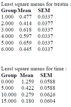
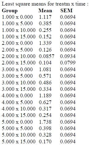
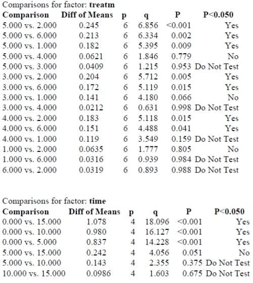
A result of “Do Not Test” occurs for a comparison when no significant difference is found between two means that enclose that comparison. For example, if you had four means sorted in order, and found no difference between means 4 vs. 2, then you would not test 4 vs. 3 and 3 vs. 2, but still test 4 vs. 1 and 3 vs. 1 (4 vs. 3 and 3 vs. 2 are enclosed by 4 vs. 2: 4 3 2 1). Note that not testing the enclosed means is a procedural rule, and a result of Do Not Test should be treated as if there is no significant difference between the means, even though one may appear to exist.
Appendix F: Samples of Data Measured in this Study
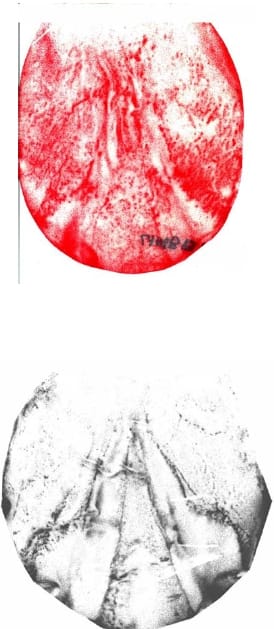
Pressure film
All the load cell data for the polystyrene pad and the total load were used. No data were rejected The computer program in appendix C was used to calculate the loads from the data presented underneath.
The data shown is for the measurement of one, four second data recording, for the total load applied to the hoof, of horse A for no polystyrene pad applied to the hoof, during the in vivo study. Do to the amount of data measured, it is not possible to show all the data in the appendix.

Voltage and Time interval
Voltage & Time Interval
-2.7881710e+000 0.0000000e+000
-2.8272350e+000 1.5625000e-002
-2.7979370e+000 3.1250000e-002
-2.8125860e+000 4.6875000e-002
-2.7979370e+000 6.2500000e-002
-2.8077030e+000 7.8125000e-002
-2.8125860e+000 9.3750000e-002
-2.8125860e+000 1.0937500e-001
-2.8321180e+000 1.2500000e-001
-2.8321180e+000 1.4062500e-001
-2.8418840e+000 1.5625000e-001
-2.8223520e+000 1.7187500e-001
-2.8272350e+000 1.8750000e-001
-2.8125860e+000 2.0312500e-001
-2.8174690e+000 2.1875000e-001
-2.8321180e+000 2.3437500e-001
-2.8467670e+000 2.5000000e-001
-2.8565320e+000 2.6562500e-001
-2.8370010e+000 2.8125000e-001
-2.8370010e+000 2.9687500e-001
-2.8321180e+000 3.1250000e-001
-2.8418840e+000 3.2812500e-001
-2.8467670e+000 3.4375000e-001
-2.8565320e+000 3.5937500e-001
-2.8662980e+000 3.7500000e-001
-2.8565320e+000 3.9062500e-001
-2.8662980e+000 4.0625000e-001
-2.8418840e+000 4.2187500e-001
-2.8418840e+000 4.3750000e-001
-2.8272350e+000 4.5312500e-001
-2.8272350e+000 4.6875000e-001
-2.8272350e+000 4.8437500e-001
-2.8223520e+000 5.0000000e-001
-2.8272350e+000 5.1562500e-001
-2.8077030e+000 5.3125000e-001
-2.8174690e+000 5.4687500e-001
-2.8125860e+000 5.6250000e-001
-2.8174690e+000 5.7812500e-001
-2.8174690e+000 5.9375000e-001
-2.8272350e+000 6.0937500e-001
-2.8321180e+000 6.2500000e-001
-2.8223520e+000 6.4062500e-001
-2.8321180e+000 6.5625000e-001
-2.8174690e+000 6.7187500e-001
-2.8272350e+000 6.8750000e-001
-2.8125860e+000 7.0312500e-001
-2.8272350e+000 7.1875000e-001
-2.8321180e+000 7.3437500e-001
-2.8321180e+000 7.5000000e-001
-2.8370010e+000 7.6562500e-001
-2.8272350e+000 7.8125000e-001
-2.8467670e+000 7.9687500e-001
-2.8467670e+000 8.1250000e-001
-2.8614150e+000 8.2812500e-001
-2.8662980e+000 8.4375000e-001
-2.8760640e+000 8.5937500e-001
-2.8907130e+000 8.7500000e-001
-2.8907130e+000 8.9062500e-001
-2.9004790e+000 9.0625000e-001
-2.8955960e+000 9.2187500e-001
-2.9053620e+000 9.3750000e-001
-2.9053620e+000 9.5312500e-001
-2.9053620e+000 9.6875000e-001
-2.9102450e+000 9.8437500e-001
-2.9004790e+000 1.0000000e+000
-2.8955960e+000 1.0156250e+000
-2.8760640e+000 1.0312500e+000
-2.8858300e+000 1.0468750e+000
-2.8711810e+000 1.0625000e+000
-2.8662980e+000 1.0781250e+000
-2.8662980e+000 1.0937500e+000
-2.8614150e+000 1.1093750e+000
-2.8662980e+000 1.1250000e+000
-2.8614150e+000 1.1406250e+000
-2.8614150e+000 1.1562500e+000
-2.8614150e+000 1.1718750e+000
-2.8662980e+000 1.1875000e+000
-2.8565320e+000 1.2031250e+000
-2.8711810e+000 1.2187500e+000
-2.8760640e+000 1.2343750e+000
-2.8760640e+000 1.2500000e+000
-2.8809470e+000 1.2656250e+000
-2.8711810e+000 1.2812500e+000
-2.8809470e+000 1.2968750e+000
-2.8711810e+000 1.3125000e+000
-2.8760640e+000 1.3281250e+000
-2.8662980e+000 1.3437500e+000
-2.8662980e+000 1.3593750e+000
-2.8711810e+000 1.3750000e+000
-2.8614150e+000 1.3906250e+000
-2.8662980e+000 1.4062500e+000
-2.8565320e+000 1.4218750e+000
-2.8711810e+000 1.4375000e+000
-2.8565320e+000 1.4531250e+000
-2.8662980e+000 1.4687500e+000
-2.8760640e+000 1.4843750e+000
-2.8711810e+000 1.5000000e+000
-2.8711810e+000 1.5156250e+000
-2.8614150e+000 1.5312500e+000
-2.8711810e+000 1.5468750e+000
-2.8614150e+000 1.5625000e+000
-2.8711810e+000 1.5781250e+000
-2.8614150e+000 1.5937500e+000
-2.8662980e+000 1.6093750e+000
-2.8760640e+000 1.6250000e+000
-2.8614150e+000 1.6406250e+000
-2.8662980e+000 1.6562500e+000
-2.8516500e+000 1.6718750e+000
-2.8614150e+000 1.6875000e+000
-2.8467670e+000 1.7031250e+000
-2.8662980e+000 1.7187500e+000
-2.8614150e+000 1.7343750e+000
-2.8614150e+000 1.7500000e+000
-2.8565320e+000 1.7656250e+000
-2.8418840e+000 1.7812500e+000
-2.8467670e+000 1.7968750e+000
-2.8370010e+000 1.8125000e+000
-2.8418840e+000 1.8281250e+000
-2.8321180e+000 1.8437500e+000
-2.8418840e+000 1.8593750e+000
-2.8516500e+000 1.8750000e+000
-2.8418840e+000 1.8906250e+000
-2.8516500e+000 1.9062500e+000
-2.8467670e+000 1.9218750e+000
-2.8516500e+000 1.9375000e+000
-2.8467670e+000 1.9531250e+000
-2.8516500e+000 1.9687500e+000
-2.8516500e+000 1.9843750e+000
-2.8467670e+000 2.0000000e+000
-2.8516500e+000 2.0156250e+000
-2.8418840e+000 2.0312500e+000
-2.8516500e+000 2.0468750e+000
-2.8370010e+000 2.0625000e+000
-2.8467670e+000 2.0781250e+000
-2.8370010e+000 2.0937500e+000
-2.8418840e+000 2.1093750e+000
-2.8516500e+000 2.1250000e+000
-2.8467670e+000 2.1406250e+000
-2.8467670e+000 2.1562500e+000
-2.8321180e+000 2.1718750e+000
-2.8467670e+000 2.1875000e+000
-2.8370010e+000 2.2031250e+000
-2.8614150e+000 2.2187500e+000
-2.8565320e+000 2.2343750e+000
-2.8516500e+000 2.2500000e+000
-2.8565320e+000 2.2656250e+000
-2.8467670e+000 2.2812500e+000
-2.8516500e+000 2.2968750e+000
-2.8370010e+000 2.3125000e+000
-2.8370010e+000 2.3281250e+000
-2.8321180e+000 2.3437500e+000
-2.8418840e+000 2.3593750e+000
-2.8418840e+000 2.3750000e+000
-2.8321180e+000 2.3906250e+000
-2.8370010e+000 2.4062500e+000
-2.8321180e+000 2.4218750e+000
-2.8418840e+000 2.4375000e+000
-2.8321180e+000 2.4531250e+000
-2.8467670e+000 2.4687500e+000
-2.8370010e+000 2.4843750e+
000
-2.8370010e+000 2.5000000e+000
-2.8418840e+000 2.5156250e+000
-2.8370010e+000 2.5312500e+000
-2.8467670e+000 2.5468750e+000
-2.8321180e+000 2.5625000e+000
-2.8418840e+000 2.5781250e+000
-2.8321180e+000 2.5937500e+000
-2.8370010e+000 2.6093750e+000
-2.8516500e+000 2.6250000e+000
-2.8418840e+000 2.6406250e+000
-2.8418840e+000 2.6562500e+000
-2.8321180e+000 2.6718750e+000
-2.8418840e+000 2.6875000e+000
-2.8272350e+000 2.7031250e+000
-2.8370010e+000 2.7187500e+000
-2.8321180e+000 2.7343750e+000
-2.8321180e+000 2.7500000e+000
-2.8370010e+000 2.7656250e+000
-2.8321180e+000 2.7812500e+000
-2.8418840e+000 2.7968750e+000
-2.8321180e+000 2.8125000e+000
-2.8467670e+000 2.8281250e+000
-2.8467670e+000 2.8437500e+000
-2.8711810e+000 2.8593750e+000
-2.8955960e+000 2.8750000e+000
-2.9248940e+000 2.8906250e+000
-2.9639580e+000 2.9062500e+000
-2.9786070e+000 2.9218750e+000
-3.0030210e+000 2.9375000e+000
-3.0079040e+000 2.9531250e+000
-3.0323190e+000 2.9687500e+000
-3.0372020e+000 2.9843750e+000
-3.0567340e+000 3.0000000e+000
-3.0665000e+000 3.0156250e+000
-3.0567340e+000 3.0312500e+000
-3.0469680e+000 3.0468750e+000
-3.0079040e+000 3.0625000e+000
-2.9786070e+000 3.0781250e+000
-2.9297770e+000 3.0937500e+000
-2.9053620e+000 3.1093750e+000
-2.8662980e+000 3.1250000e+000
-2.8370010e+000 3.1406250e+000
-2.8174690e+000 3.1562500e+000
-2.8028200e+000 3.1718750e+000
-2.8125860e+000 3.1875000e+000
-2.8125860e+000 3.2031250e+000
-2.8565320e+000 3.2187500e+000
-2.8809470e+000 3.2343750e+000
-2.9200110e+000 3.2500000e+000
-2.9590750e+000 3.2656250e+000
-2.9883720e+000 3.2812500e+000
-3.0176700e+000 3.2968750e+000
-3.0127870e+000 3.3125000e+000
-3.0323190e+000 3.3281250e+000
-3.0176700e+000 3.3437500e+000
-3.0127870e+000 3.3593750e+000
-2.9834890e+000 3.3750000e+000
-2.9541920e+000 3.3906250e+000
-2.9248940e+000 3.4062500e+000
-2.8809470e+000 3.4218750e+000
-2.8370010e+000 3.4375000e+000
-2.7588730e+000 3.4531250e+000
-2.7149270e+000 3.4687500e+000
-2.6758630e+000 3.4843750e+000
-2.6563310e+000 3.5000000e+000
-2.6416820e+000 3.5156250e+000
-2.6270330e+000 3.5312500e+000
-2.6221500e+000 3.5468750e+000
-2.6026180e+000 3.5625000e+000
-2.6221500e+000 3.5781250e+000
-2.6319160e+000 3.5937500e+000
-2.6563310e+000 3.6093750e+000
-2.6660970e+000 3.6250000e+000
-2.6856290e+000 3.6406250e+000
-2.7100440e+000 3.6562500e+000
-2.7100440e+000 3.6718750e+000
-2.7344580e+000 3.6875000e+000
-2.7198100e+000 3.7031250e+000
-2.7295750e+000 3.7187500e+000
-2.7246930e+000 3.7343750e+000
-2.7344580e+000 3.7500000e+000
-2.7491070e+000 3.7656250e+000
-2.7637560e+000 3.7812500e+000
-2.7735220e+000 3.7968750e+000
-2.7930540e+000 3.8125000e+000
-2.8418840e+000 3.8281250e+000
-2.8662980e+000 3.8437500e+000
-2.8955960e+000 3.8593750e+000
-2.9102450e+000 3.8750000e+000
-2.9248940e+000 3.8906250e+000
-2.9297770e+000 3.9062500e+000
-2.9200110e+000 3.9218750e+000
-2.9151280e+000 3.9375000e+000
-2.8858300e+000 3.9531250e+000
-2.8711810e+000 3.9687500e+000
-2.8321180e+000 3.9843750e+000
References
- Balch O, Butler D, White K, Metcalf S 1995 Hoof balance and lameness: Improper toe length, hoof angle, and mediolateral balance. Compendium on Continuing Education 17: 1275- 1283
- Balch O, White K, Butler D 1991 Factors involved in the balancing of equine hooves. Journal of the American Veterinary Medical Association 198: 1980-1989
- Barrey E 1990 Investigation of the vertical hoof force distribution in the equine forelimb with an instrumented horseboot. Equine Veterinary Journal Suppl 9: 35-38
- Bartel D L, Schryver H F, Lowe J E, Parker R A 1978 Locomotion in the horse: A procedure for computing the internal forces in the digit. American Journal of Veterinary Research 39: 1721-1727
- Baxter G M 1996 Diagnosing and treating acute laminitis. Veterinary Medicine 91: 940-952
- Baxter G M 1992 Equine laminitis. Equine Practice 14: 13-22
- Butler, J A, Colles, C M, Dyson, S J, Kold, S E, and Poulos, P W 1993 Clinical Radiology of the Horse Blackwell Scientific Publications, London
- Chapman B 1996 The most frequently asked questions and answers about laminitis and founder. American Farriers Journal 22: 42-46
- Chapman B, Platt G W 1985 Laminitis. Proceedings of the 31st Annual Convention of the American Association of Equine Practitioners. 99-116
- Colahan P, Leach D, Muir G 1991 Center of pressure location of the hoof with and without hoof wedges. In Persson S G B, Lindholm A, Jeffcott L B (eds) Equine Exercise Physiology 3. ICEEP Publications, Davis, California: 113-119
- Colahan P, Lindsey E, Nunier C 1993 Determination of the center of pressure of the hooves of the forelimbs of horses standing on a flat level surface. Acta Anatomica 146: 175-178
- Colles C M 1986 Diseases and injuries of the horse’s foot. In Hickman J (ed) Equine Surgery and Medicine Vol 2. Academic Press, London, UK: 185-223
- Colles C M 1989 A technique for assessing hoof function in the horse. Equine Veterinary Journal 21: 17-22
- Colles C M 1991 Laminitis Research. Equine Veterinary Journal 23: 237-238
- Cripps P J, Eustace R A 1999 Radiological measurements from the feet of normal horses with relevance to laminitis. Equine Veterinary Journal 31: 427-432
- Curtis S, Ferguson D W, Luikart R, Ovnicek G 1999 Trimming and shoeing the cronically affected horse. Veterinary Clinics of North America: Equine Practice 15: 463-480
- Douglas J E, Mittal C, Thomason J J, Jofriet J C 1996 The modulus of elasticity of equine hoof wall: implications for the mechanical function of the hoof. The Journal of Experimental Biology 199: 1829-1836
- Eastman T G, Honnas C M, Hague B A, Moyer W, von der Rosen H D 1999 Deep digital flexor tenotomy as a treatment for chronic laminitis in horses: 35 cases (1988 – 1997). Journal of the American Veterinary Medical Association 214: 517- 519
- Eustace R A 1990 Equine laminitis. In Practice 156-161
- Eustace R A 1992 Explaining Laminitis and its Prevention. J W Arrowsmith Ltd, Bristol
- Eustace R A 1993 Equine Laminitis. In Boden E (eds) Equine Practice. Bailliere Tindall, London: 149-164
- Eustace R A, Caldwell M N 1989 The construction of the heart bar shoe and the technique of dorsal wall resection. Equine Veterinary Journal 21: 367-369
- Eustace R A, Caldwell M N 1989 Treatment of solar prolapse using the heart bar shoe and dorsal hoof wall resection technique. Equine Veterinary Journal 21: 370-372
- Frederick F H, Henderson J M 1970 Impact force measurement using preloaded transducers. American Journal of Veterinary Research 31: 2279-2283
- Goetz T E 1987 Anatomic, hoof, and shoeing considerations for the treatment of laminitis in horses. Journal of the American Veterinary Medical Association 190: 1323-1332
- Goetz T E 1987 Dorsal hoof-wall removal for the treatment of laminitis. American Farriers Journal 50-64
- Goetz T E 1989 The treatment of laminitis in horses. Veterinary Clinics of North America:Equine Practice 5: 73-108
- Goetz T E, Comstock C M 1985 The use of adjustable heart bar shoes in the treatment of laminitis in horses. Proceedings of the 31st Annual Convention of the American Association of Equine Practitioners 605-616
- Hood D M, Beckham A S, Chaffin M K, Hunter J F, Mathews N S, Moyer W, Slater M R 1995 Comparison of phenylbutazone, lily pads, and trimming on expressed pain in horses with chronic laminitis. Proceedings of the 41th Annual Convention of the American Association of Equine Practiti
oners 248-250 - Hood D M, Grosenbaugh D A, Slater M R 1994 Vascular perfusion in horses with chronic laminitis. Equine Veterinary Journal 26: 191-196
- Hunt R J 1991 The pathophysiology of acute laminitis. Compendium on Continuing Education for the Practicing Veterinarian 13: 1003-1011
- Hunt R J 1993 A retrospective evaluation of laminitis in horses. Equine Veterinary Journal 25: 61-64
- Hunt R J 1996 Diagnosing and treating chronic laminitis in horses. Veterinary Medicine 91: 1025-1032
- Kasapi M A, Gosline J M 1996 Strain-rate-dependent mechanical properties of the equine hoof wall. The Journal of Experimental Biology 199: 1133-1146
- Le Roux, J M W and Smuts, M M S 1986 Anatomie van die Huisdiere – ‘n Studie en Disseksiegids Promedia Publikasies, Pretoria
- Leach D 1984 Biomechanical considerations in raising and lowering the heel. Proceedings of the 29th Annual Convention of the American Association of Equine Practitioners 333-342
- Moore J N, Allen D 1996 The pathophysiology of acute laminitis. Veterinary Medicine 91: 936- 939
- Moore J N, Allen D, Clark E S 1991 Pathophysiology of acute laminitis. Equine Practice 13: 29- 32
- Moyer W, Redden R R 1989 Chronic and severe laminitis: a critique of therapy with heart bar shoes and hoof wall resection. Equine Veterinary Journal 21: 317-318
- O’Brien T R, Baker T W 1987 Distal extremity examination: How to perform the radiographic examination and interpret the radiographs. Proceedings of the 32nd Annual Convention of the American Association of Equine Practitioners 553-570
- O’Grady S E 1992 Treating acute laminitis. Equine Veterinary Data 13: 124-126
- Olivier A 1992 The effect of the reverse even frog pressure shoe on hoof wall compression and third phalanx displacement in the horse – an in vitro study. M.Med.Vet.(Chir), Faculty of Veterinary Science, University of Pretoria
- Ovnicek G D. Page B T, Trotter G W 2003 Natural balance trimming and shoeing: its theory and application. Veterinary Clinics: Equine Practice 19: 353-377
- Page B T, Bowker R M, Ovnicek G D, Hagen T L, 1999 How to mark the foot for radiography. Proceedings of the 45th Annual Convention of the American Association of Equine Practitioners 148-150
- Parks A H 2003 Treatment of acute laminitis. Equine Veterinary Education 15: 273-280
- Peremans K, Verschooten F, De Moor A, Desmet P 1991 Laminitis in the pony: conservative treatment vs dorsal hoof wall resection. Equine Veterinary Journal 23: 243-246
- Pollitt C 1998 An overview of laminitis. Proceedings of the 30th Annual Congress of the Equine Practitioners Group of the South African Veterinary Association 55-59
- Pollitt C C 1996 Basement membrane pathology: a feature of acute equine laminitis. Equine Veterinary Journal 28: 38-46
- Pollitt C C 1996 The basement membrane at the equine hoof dermal epidermal junction. Equine Veterinary Journal 26: 399-407
- Pollitt C C 1999 Equine Laminitis: A Revised Pathophysiology. Proceedings of the 45th Annual Convention of the American Association of Equine Practitioners 188-192
- Prinz L 1996 Arresting laminitis. Equus 228: 47-53
- Redden R F 1986 Hoof wall resection as a treatment in laminitis. Proceedings of the 32th Annual Convention of the American Association of Equine Practitioners 647-656
- Redden R F 1988 Complicated laminitis. Proceedings of the 34th Annual Convention of the American Association of Equine Practitioners 311-319
- Redden R F 1992 18o elevation of the heel as an aid to treating acute and chronic laminitis in the equine. Proceedings of the 38th Annual Convention of the American Association of Equine Practitioners 375-379
- Redden R F 2003 Radiographic imaging of the equine foot. Veterinary Clinics: Equine Practice 19: 379-392
- Reddy J N 1984 An introduction to the finite element method McGraw-Hill Book Company, New York
- Sigafoos R 1994 New management approaches to laminitis. Equine Veterinary Data 15: 135-135
- Skog W J, Reinertson E L 1985 Theory and application of the Chapman heartbar horseshoe for laminitis. Iowa State University Veterinarian 47: 90-97
- Sloet van Oldruitenborgh-Oosterbaan M M 1999 Laminitis in the horse: a review. Veterinary Quarterly 21: 121-127
- Stashak T S 1987 Lameness. Adam’s Lameness in Horses. Lea and Febiger, Philadelphia: 486- 499
- Thomason J J, Biewener A A, Bertram J E A 1992 Surface strain on the equine hoof wall in vivo: Implications for the material design and functional morphology of the wall. Journal of Experimental Biology 166: 145-168
- Van den Berg S S 1997 Recent developments in the therapy of equine laminitis. Equine Practitioners Group Short Course 29: 24-32
- Weiss D J 1997 Equine laminitis: a review of recent research. Equine Practice 19: 16-20
- White N A, Baggett N 1983 A method of corrective shoeing for laminitis in horses. Veterinary Medicine and Small Animal Clinician 775-778
- Wilson J H, Turner T A 1991 Medical management of laminitis. Equine Veterinary Data 12: 219- 220
- Yelle M 1986 Clinicians guide to equine laminitis. Equine Veterinary Journal 18: 156-158
