

Article
Related Links
R.H.W. ten Thije*, R. Akkerman
University of Twente
ABSTRACT: Friction plays an important role in forming processes of thermoplastic laminates. A model is currently developed to predict the frictional properties of these materials and validation experiments are being conducted. The development of a friction measurement rig for thermoplastic composites is not straightforward. Controlling the transverse pressure profile on the laminate is essential for accurate measurements. Mould deflections and the setup type used (pullout versus pull-through) have a significant effect on homogeneity of the profile. This is validated by measurements of the pressure profile and analyses of the experimental setup. In turn, the inhomogeneity of the pressure profile can make the experimentally obtained friction properties unsuitable for model validation.
KEYWORDS: friction, lubrication, thermoplastic, composite, forming
Introduction
Continuous fibre reinforced thermoplastics offer a cost reduction compared to thermosets due to promising fast production methods such as diaphragm forming and rubber pressing. Friction plays an important role in these forming processes [1–5].The constraints imposed by friction between subsequent plies and between the laminate and the tools are a major factor in the laminate deformations generated during composite forming.
Friction depends on the forming process parameters such as the pressure, the temperature and the sliding velocity. In addition, it will depend on the material properties of the fibres and the resin, the fibre distribution and the reinforcement architecture, as for any composite property. An appropriate model is needed for an accurate description of the frictional phenomena in the general case, taking into account the effects of the various governing parameters. Such a model is currently developed at the University of Twente and validation experiments are being conducted. The development of a friction measurement rig for these thermoplastic composites is not straightforward. This article addresses some of the drawbacks of the current experimental setup that need to be eliminated in a new design.
2 Friction Model and Experimental Results
A model is developed that predicts the friction between thermoplastic laminates and a rigid steel tool by assuming hydrodynamic lubrication on a meso-mechanical level. With this, we aim to develop a generic prediction method with only fabric geometry data and resin data as the input. Details on the model can be found in the papers [6, 7]. Figure 1 shows a schematic representation of the current experimental setup used for the corresponding validation experiments. A laminate is pulled from between two platens in these experiments. The temperature and the exerted normal force are controlled during the test. The total platen area is equal to 195 x 195 mm. Figure 2 shows two resulting Stribeck curves, one for Twintex material and one for a 8HS/PPS laminate. We use these two examples to support our hypothesis that mould deflections are the cause for the deviations found between the model and the experimental results of the latter one. More experimental results and details on the fabric types and resins can be found in [6, 7]. Excellent correspondence between the experimental results and the model was found for coarse fabrics, like the 2×2 twill/PP (Twintex) material shown in figure 2. The results for more delicate 8 harness satin/PPS laminates showed significant deviations for higher sliding velocities. We have strong reasons to believe that the deviations are caused by the boundary conditions of our experiments. Or the other way around: the boundary conditions of our model are not equal to the experimental boundary conditions. The assumption of a rigid tool results in a homogeneous pressure distribution on the laminate. In the following sections we present experimental and analytical results that show that the deflections of the platens are not negligible and that these deflections can be the cause of the deviations between the predicted and measured coefficient of friction.
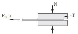
Figure 1: Schematic representation of the experimental pull-out setup.
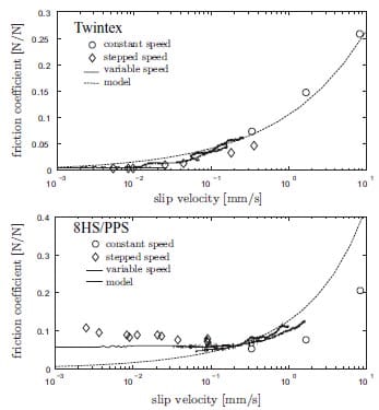
Figure 2: Stribeck curves for Twintex and 8HS/PPS at a normal pressure of 42.11 kPa and a temperature of 200oC and 305oC respectively.
3 Pressure Profile Measurements
The pressure distribution on a laminate was measured. For this, an 8HS weave was impregnated with liquid Van Gilse sugar sirup. This sirup has a viscosity that corresponds to the viscosity of PPS at 300oC. Figure 3 shows a picture of an impregnated fabric. This fabric was clamped together with a Pressurex® pressure indicating sensor film between the two platens of the experimental setup. The clamped surface area of the impregnated fabric amounts to 195 x 50 mm. A total clamping force of 3500 N was exerted on the platens. Figure 4 shows the measured pressure distribution. The measured pressure distribution significantly deviates from a homogenous pressure of 0.36 MPa, which is expected based on the assumption of rigid tooling. The pressure distribution plot along the line A – A1 shows that the pressure at both ends of the platens is twice as large as the nominal pressure, while the pressure in the centre of the laminate is nearly zero.
4 Pressure Profile Analysis
This section shows the results of analytical analyses of the mould pressure distribution. These results are useful in designing future experimental setups. First, the effect of a pull-out and a pull-through setup on the pressure distribution is investigated. Second, the effect of mould deflections are taken into account.
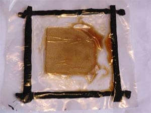
Figure 3: 8HS weave impregnated with liquid sugar sirup. Dimensions of the weave: 80 x 80 mm.
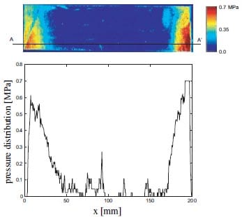
Figure 4: Pressure distribution on the impregnated fabric. The bottom graph shows the distribution along line A – A
4.1 Pull-out Versus pull-through
Figure 5 shows a schematic setup of a pull-out setup. The laminate is pulled from between the two platens, leaving a gap that introduces a pressure inhomogeneity. The effect of the gap on the pressure distribution is estimated by an analysis in whi
ch the tooling is considered rigid and the laminate deformable. The distributed load q on the laminate equals q(x) = k · w, in which k denotes the transverse stiffness of the laminate and w the transverse compression of the laminate. Quadrature of this load results in the total compaction force. The rigid tooling assumption leads to a linearly distributed load q. The equilibrium equations are used to find the resulting pressure distribution. Figure 6 shows the resulting pressure distributions on the laminate due to a pull-out length of 20 mm. Experiments have shown that a total pull-out length of 20 mm is necessary to capture all start-up phenomena during tool-laminate friction and to arrive in a ’steady-state’ situation. Two different platen dimensions were used: 100 and 200 mm respectively. The external force is chosen such that the homogenous initial pressure on the laminate is equal to 1 Pa. Figure 6 shows that the effect of the pull-out length and the platen dimensions are significant. A larger platen will reduce the inhomogeneity. To reduce the pressure over- and undershoot to less than 10% of the nominal pressure, the length of the platens has to be over 860 mm. This will increase the deflection of the platens, an effect that is addressed in the following section.
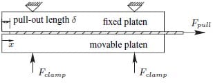
Figure 5: Schematics of a pull-out setup.
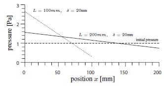
Figure 6: Pressure distribution after a pull out length of 20 mm with a total platen length of 100 and 200 mm respectively.
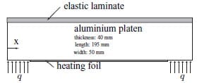
Figure 7: The platen modelled as a beam on an elastic foundation.
Figure 8: The transverse pressure distribution on the laminate.
4.2 Mould Deflections
Figure 7 shows a cross section of a platen from the current experimental setup. This aluminium platen is backed by a steel backing plate. Loads are only transferred at the outer 25 mm of the platen, since the heating foil is unsuited for mechanical loading. The laminate is regarded as an elastic foundation, which is connected to the platen. This system is modelled using the classical beam analysis:
in which EI denotes the bending stiffness, k the transverse stiffness of the laminate and w the beam deflection. Rotations of the edges of the platen are partly suppressed by the steel backing plate. Since the exact boundary condition is unknown, the two extreme boundary conditions are both evaluated here. Either the edges are free to rotate, situation A, or they are suppressed, situation B. The transverse shear force equals zero at both ends of the beam for both situations. This results in the following boundary conditions for the equation:

The Young’s modulus E of the aluminium beam is set to 70 GPa. The moment of inertia I equals 1 1/2bh3. The dimensions are found in figure 7. The distributed load q equals 70 N/mm and is applied over a length of two times 25 mm. The total applied force equals 3500 N, identical to the load applied during the experimental measurement of the laminate pressure in section 3. The transverse stiffness k is set to 0.2 N/mm. Figure 8 shows the resulting pressure distributions in the laminate for the cases A and B. Clamping the edges, situation B, has a positive effect on the pressure homogeneity. The calculated pressure distribution is similar to the measured distribution from section 3 for the current transverse laminate stiffness k chosen. This allows for studying the effect of platen dimensions and loading scenarios. E.g. to reduce the pressure over- and undershoot to less than 10% of the nominal pressure in the current configuration, the thickness of the aluminium platen has to be increased to at least 175 mm.
5 Effects on the Friction Model
The experimental and predicted results for the 8HS/PPS frictional tests are shown in figure 2. The value predicted by the friction model (section 2) for a slip velocity of 8.3 mm/s was obtained by assuming a homogenous pressure of 42.11 kPa. Figure 9 shows three additional pressure profiles that were used as input for the friction model. Al profiles have a nominal pressure value of 42.11 kPa. Profile D shows the most resemblance to the experimentally determined pressure profile. The coefficient of friction predicted by the model based on these four profiles is plotted in figure 10. The numbers illustrate that the pressure distribution has a significant effect on the coefficient of friction. The pressure inhomogeneities in the experimental setup need to be eliminated for accurate validation experiments.
6 Discussion
The design of an experimental setup to measure toolply and ply-ply friction in thermoplastic laminates is not straightforward. Experimental work in the past pointed out that the minimal slip length must be 20 mm to capture both the start-up and the steady-state effects of this type of friction. Transverse pressures on the laminate need to be homogeneous to make the validation of frictional models with these experimental results possible. The analysis of the pull-out setup from section 4.1 illustrates that a this type of setup results in impractically large moulds. A pullthrough setup is therefore prevailed.
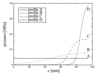
Figure 9: Four different pressure profiles with an identical nominal pressure.
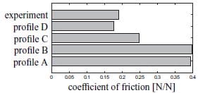
Figure 10: Predicted coefficients of friction based on the pressure profiles and the experimentally obtained value.
The beam analysis from section 4.2 allows for a prediction of the transverse deflections and pressure profiles for varying mould dimensions. The new experimental test rig that is currently under construction at the University of Twente has steel platens of 50 x 50 mm with a thickness of 40 mm. This reduces the deviations in the pressure profile to less than 3% of the nominal pressure. Care should be taken when developing an experimental friction rig with large platens, since minor deflections can cause unusable results. An additional pressure distribution measurement with the pressure sensitive foil was performed to validate the beam model. The geometry of the platen used to compress the fabric/sirup laminate is shown in figure 11. The model predicts deviations in the pressure profile of 5% of the nominal pressure. Figure 11 shows that the pressure profile is indeed much more homogeneous when compared to the profile resulting from the current experimental setup.
7 Conclusions and Outlook
Controlling the transverse pressure profile on a thermoplastic laminate is essential for accurate measurements of the frictional properties. Mould deflections and the setup type used (pull-out versus pull-through) are major factors that effect the homogeneity of the profile. A pull-through setup is prevailed over a pull-out setup due to the impractically large platen dimensions needed for a homogenous transverse pressure profile in a pull-out setup. Minor
platen deflections can have a significant effect on the pressure profile and hence on the experimental results. A model has been developed to analyse whether the deflections are acceptable.A new experimental setup is currently under construction at the University of Twente. The conclusions stated here are taken into account in the design of the new setup. The experimental results obtained with the new setup will be used to validate our hypothesis that the transverse pressure profile is of major importance.
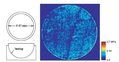
Figure 11: Pressure distribution measurement on a circular geometry.
Acknowledgement
The authors wish to thank Stork Fokker AESP and Ten Cate Advanced Composites for their cooperation.
- Jennifer L. Gorczyca-Cole, James A. Sherwood, and Julie Chen. A friction model for thermostamping commingled glasspolypropylene woven fabrics. Compos Part A-Appl S, 38:393–406, 2007.
- Gilbert Lebrun, Martin N. Bureau, and Johanne Denault. Thermoforming-stamping of continuous glass fiber/polypropylene composites: Interlaminar and toollaminate shear properties. J Thermoplast Compos, 17:137–165, 2004.
- H. Lin, P. Harrison, K. van de Haar, A. C. Long, R. Akkerman, and M. J. Clifford. Investigation of tool-ply friction of viscous textile composites. In Proc TEXCOMP-8, 2006. CD-edition.
- A. M. Murtagh, M. R. Monaghan, and P. J. Mallon. Investigation of the interply slip process in continuous fibre thermoplastic composites. In Proc 9th ICCM Conf, 1993.
- An Willems. Forming simulation of textile reinforced composite shell structures. PhD thesis, University of Leuven, Belgium, 2008. ISBN 978-94-6018-009-5.
- R. Akkerman, M. P. Ubbink, M. B. de Rooij, and R. H. W. ten Thije. Tool-ply friction in composite forming. In Proc 10th Int ESAFORM Conf, 2007.
- R. Akkerman L. van der Meer R. H. W. ten Thije and M. P. Ubbink. Tool-ply friction in thermoplastic composite forming. In Proc 11th Int ESAFORM Conf, 2008.
