


Article
Related Links
Article: American Tool, Die & Stamping News
by Mirco Graenert, Consultant and Jeffrey Stark, President Sensor Products Inc
Pressurex®, a thin flexible Mylar-based sensor film that instantly captures and permanently records pressure distribution and magnitude between any two mating or contacting surfaces, reduces punch breaks and the frequency of die sharpening in stamping operations. By pinpointing important pressure points that affect tool balancing and key pressure areas that lead to die wear, the film can be used to reduce long term production maintenance costs.
Shawn Eeles, general manager of Five Star Tooling, a progressive die manufacturer in Ontario, Canada, put Pressurex® through a 400-ton progressive die trial to analyze its capabilities. Initially a series of tests were conducted with the pressure-indicating film by using a 12-ton shop press and some stamping and forming die components. The initial test proved that Pressurex® can reveal pressures accurately in die forming and piercing operations. A progressive stamping die nearing build completion was chosen and by using hands-on steel stamping experience, they were able to pinpoint important pressure points affecting tool balancing, as well as the key pressure areas affecting die wear.
Although significant effort goes into the design and planning of the balancing event in the stamping tool during the design phase, verifiable data can only be obtained in a press, ideally near completion of the die build phase and first full strip press try out. The die test setup used is shown in Figure A. The die is a medium size stamping tool which manufactures parts from a coil of steel. It is about 5 feet (approx. 1.5 meters) in length, manufacturing an arched structural car component using material of about .080″ (2mm) in thickness.
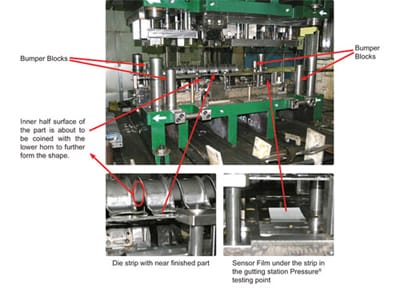
Figure A – The 400T pressure testing setup shows the die components and bumper blocks.
Stamping tool designers, tool-makers and engineers know that it is vital to balance the overall processes of metal cuts and strikes, which are required to shape a part progressively in a die. Balancing and obtaining pressure readings from the various operations accurately result in higher quality dies and reduced future die maintenance costs.
The traditional method, the ages-old die spotting blue technique, reveals the pressure points without actual pressure readings, making balancing in relation to other die components difficult. Although knowledgeable plant personnel are needed to make the fine adjustments repeatedly on the press for ongoing production, the initial die build and balancing are vital for positive long term results. The re-strike station, particularly on thicker or formed materials, often exerts a concentrated force near the exit side of the die. Unbalanced pressures can cause the die to "kick," resulting in premature fatigue, excess wear and subsequent cracking or breakage of die components. Optimal balance throughout the die is achieved by paying close attention to pressure readings from the film and making adjustments in the gutting station area, usually by varying the stripper pressures when balancing infeed to output die ends.
Pressurex® film was also used to analyze the pressure on and around the cutting edges of a progressive die assembly (shown in Figure B).
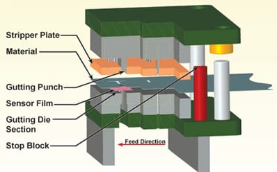
Figure B – Pressurex® is placed in the progressive die
between the material strip and the lower gutting section to determine
punch and stripper pressures.
As per the above illustration, when the press and upper die gutting punches move down, they contact the material strip shortly after the stripper clamps the material in place. Further downward motion causes the compressive forces to act on the microcapsules of the sensor film just before cutting through the strip and film. This pressure causes the sensor film’s microcapsules to burst, producing an instantaneous and permanent high resolution "topographical" image of pressure variation across the contact area. After one full press stroke, the film is removed and examined.
Similar in thickness to ordinary paper, Pressurex® can be quickly placed between many mating forming surfaces and cutting edges. The film changes color directly proportional to the amount of pressure applied and accurately reveals whether pressures are evenly distributed (shown in Figure C). Precise pressure distribution is determined by comparing the exposed sensor film to a color calibration reference chart. High pressure areas near the cutting edges are caused by local material strip deformation.
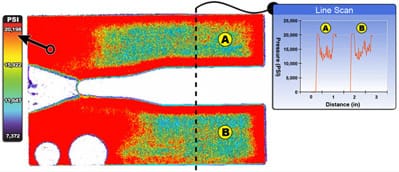
Figure C – A cut through of the sensor film reveals stipping and gutting punch
forces. The line scan represents cross-sectional forces.
Pressurex® can be further analyzed using Sensor Product’s in-house imaging service or by leasing or purchasing their Topaq® Tactile Force Analysis System. All images in this article have been analyzed with Topaq®.
The film showed the areas which were doing most of the work in this die station and provided valuable data during the metal bending "pre-form" die operation as well. Details of their analysis follow.
In Figure D, the film shows the precise pressure distribution and actual pressure values in the die and allows them to take action (such as adjusting the springs or changing the amount of contact forming pressures in the die) to correct imbalances or excessive pressures before die-build completion. The cutting edges in the gutting operation, compared to the restrike forms, showed similar pressures and were similarly adjusted.
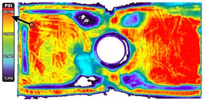
Figure D – Film shows tactile analysis of the curved restrike operation.
In Figure E, the film showed the dies’ outer four bumper blocks, the principal indicators of die parallelism. The film revealed detailed data about differences in pressures across the small sections of bumper blocks, unlike traditional lead check "distance only" measurements.
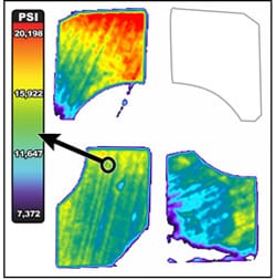
Figure E: Three of the four bumper blocks saw
pressure ranges between 7,000 and 20,000 PSI. The fourth bumper
block did not have any contact. A shut height correction was made.
The general problem with bumper blocks is that the die really should not contact these blocks at all or beyond an established pressure range; however, if conventionally measuring with lead-free round solder, no difference can be found after the zero point of contact has been reached. The pressure indicating sensor film still reads a pressure until the limit has been exceeded.
The test proved that bumper blocks, areas near cutting edges, gradual forms, trim cutting edges, and re-strike stations can all be thoroughly analyzed giving vital information that enables better die balancing. Even many heavier (> 0.080" – approx. 2mm) automotive and other stamping and value-added assembly applications are measurable, starting from dies that stamp copper tabs inside a cars light switch to stamped closure components. SPI’s Pressurex® is simple to use and analyze. It is inexpensive and provides significantly more data than other analysis methods
For some dies, these pressure values, particularly combined with die knowledge, reveal what is ‘unseen’ and allow dies and other mechanical systems to be fine-tuned, which reduces their life cycle maintenance cost and improves part quality and consistency. Only the tip of the iceberg has been explored by using the sensor film in a particular progressive metal stamping tool. There are virtually no limits to what this film can reveal in metal stamping, assembly and related applications.
Pressurex® reveals surface pressure from 2 – 43,200 PSI (0.14 – 3,000 kg/cm²) and is available in eight distinct pressure ranges. The film measures tactile pressure magnitude and distribution in clamps, bolted joints, composites, presses, gaskets, fuel cells, molds, brakes, valves, heat seals, and scores of other industrial applications.