
Categories
-
Fujifilm Prescale (22)
-

Fujifilm Sample Pack (2)
-
Fujifilm Prescale/Topaq 3x3 (1)
-
Application Kits (6)
-
Fujifilm UVScale (2)
-
Pressurex-micro (1)
-
EZ-Nip impression paper (1)
-
Mold-Align (2)
-
Manuals (1)
-
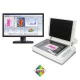
Topaq Imaging Analysis (1)
-
Auto-Nis Scanner System (1)
-
DigiNip (2)
-
Thermoscale (1)
-
Thermex Paper (1)
-
TemprX (2)
-
Pressure Man Children's Book (1)

Shopping Cart
-
Fujifilm Prescale (22)
-
Fujifilm Sample Pack (2)
-
Fujifilm Prescale/Topaq 3x3 (1)
-
Application Kits (6)
-
Fujifilm UVScale (2)
-
Pressurex-micro (1)
-
EZ-Nip impression paper (1)
-
Mold-Align (2)
-
Manuals (1)
-
Topaq Imaging Analysis (1)
-
Auto-Nis Scanner System (1)
-
DigiNip (2)
-
Thermoscale (1)
-
Thermex Paper (1)
-
TemprX (2)
-
Pressure Man Children's Book (1)