


Executive Summary
The nip impression and its relation to force are presented, along with the procedure for obtaining and reading a nip impression. Several common nip impression examples are included, with interpretations of each.
The importance of roll crowning is explained, along with deformation and crown calculations. Included are a discussion of crown contour vs. crown at center of roll, and the concept of compound crowning to allow for end relief in addition to a simple straight dub or taper.
Modern problem solving tools for rolls and roll covers are available to Metso’s customers. These include computer simulations such as NipSim® for nip dynamics. PresSim® is used for press modeling. FlowSim® is used for roll finishing (drilling or grooving) and the associated effects on the machine water balance. Finally, RollTracer® is a roll tracking database. Examples of each tool are included.
The nip impression
A machine with two or more rolls whose surfaces are forced against each other is a very common device found in a number of industries. It is used in several industries, including papermaking, textile manufacturing, printing, metal forming and rubber manufacturing. Its common purpose is to apply a force to a web going between the rolls. The reason for this application of force, however, is different from industry to industry as well as within a given industry.
For example, in papermaking this force is applied to remove water, to apply coatings, for smoothing and calendering or simply drying. The interface where two rolls meet is called a nip and is very important to the processor, since the configuration of the nip describes not only the amount of force being applied, but also the distribution of the force. Consequently, in situations where force is an important parameter, a measurement of the nip is highly advantageous. Such a measurement can be obtained for covered rolls through the use of a tool known as “the nip impression”. This is exactly what the name implies, an impression of the nip. Because the nip is the total contact surface between the two rolls, the nip impression, therefore, would be an impression made across the entire contact area.
Measuring the nip
Obtaining the nip impression over the years has been accomplished by a number of different techniques. In addition to carbon nip impressions, there are two other techniques commonly used today – electronic nip impressions and Fuji nip impressions. Each method is different and has its specific advantages. Carbon nips are considered static, they represent one load, one point in time and the rolls are still while the test is being performed. Both electronic nip impressions and Fuji nip impressions are considered dynamic.
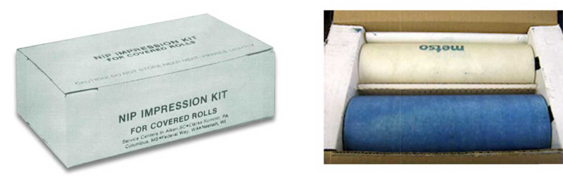
Figure 1. Metso Nip Impression Kit
Carbon paper method (static)
Traditionally, the use of carbon nip impression paper has been common. (e.g. Metso Nip Impression Kit, Figure 1). The kit is a roll of carbon paper and a roll of plain white paper, wherein the desired length of both can be dispensed with the carbon side flush against the white paper. Carbon nips are still recommended for verification of any crown change. The nip width is measured by a simple carbon transfer from the carbon paper to the plain paper under pressure. Most frequently waxed carbon paper is used, but for high temperature applications a kit without wax is preferred. On the next page is a generic procedure for conducting carbon nip impressions.
With the use of the Nip Impression Kit, the impression is taken as follows:
NOTE: Nip impressions should be taken with the machine down and the felts removed.
- Dispense a length of two papers equivalent to 12″ greater than the face length of the mating rolls.
- Open the nip to insert the nip impression paper without any interference from the rolls.
- Insert the nip impression paper so that it is covering the contact area of the two mating rolls. There should be about 6″ of covering paper overhanging at each end.
- Carefully position the paper so that the nip is centered in the machine direction on the paper. Be certain that the paper is smooth and lying flat. If possible, tape the paper to the roll at a few points to insure its remaining flat and smooth until it is removed from the rolls. Make sure no tape will be in the nip.
- Go to close with the press to zero load, making sure that the press closes evenly. This prevents a skew in the results from a press that does not close evenly. Then go to load and insure that equilibrium conditions are attained. In some cases, it may take several minutes to obtain equilibrium.
- Open the press and remove the paper. Remove and dispose of the carbon sheet. The carbon nip impression created by the press will be on the white paper.
- Repeat this process. If the press is mechanically sound, it closes evenly, and the procedure is correctly followed – the results should be repeatable.
It is best at this time to document the following on the paper: the load at drive side and/or tending side, the date, location of the rolls, length, diameters, cover thickness of the rolls and any other pertinent data relating to the nip.
Electronic method (dynamic)
Electronic nip impressions measure the nip over a span of time. During this time, the load can be changed and how the press reacts to these changes can be recorded. This can be very advantageous when more than one load needs to be considered or when troubleshooting press loading. It also takes much less time to gather the information. The nip information is gathered immediately and constantly for the period that the blanket is in the nip. In most cases, more than one nip can be measured at one time and the ability to repeat the results can be performed much quicker than with carbon paper.
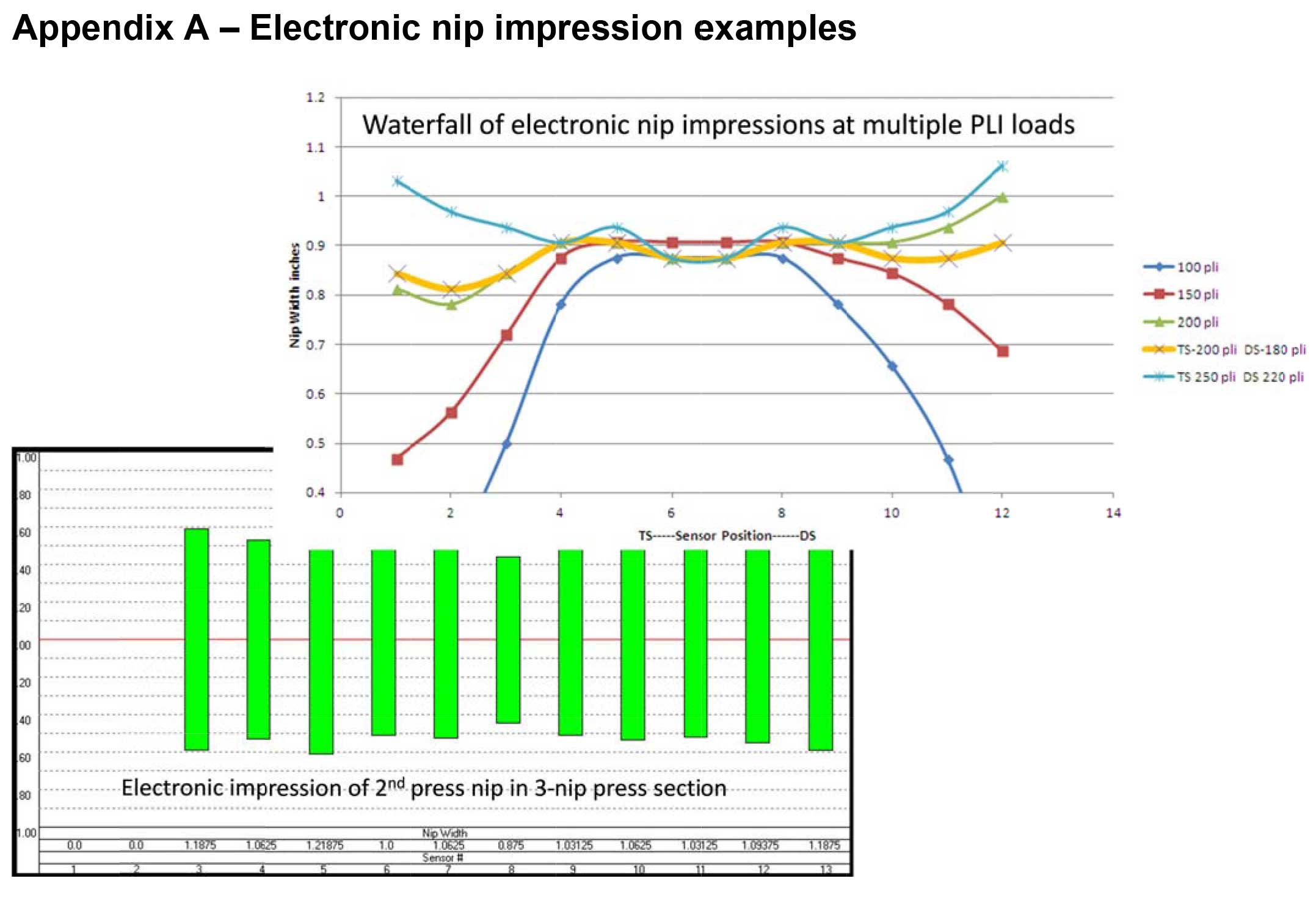
The procedure for conducting electronic nip impressions is somewhat similar to carbon paper. An electronic blanket is attached to a hub and the mA current signals from the blanket are converted into nip widths via proprietary software. The nip impression is not a continuous profile across the face length of the roll, because the sensors are on centers of 45 cm, 60 cm, and 75 cm. If there are disadvantages when compared to carbon, they are as follows: the information is not continuous across the roll face length; the equipment is expensive and not as readily available as carbon paper. The advantage is a tremendous amount of flexibility. For examples on output received from electronic nip impressions, see Appendix A.
Fuji method (dynamic)
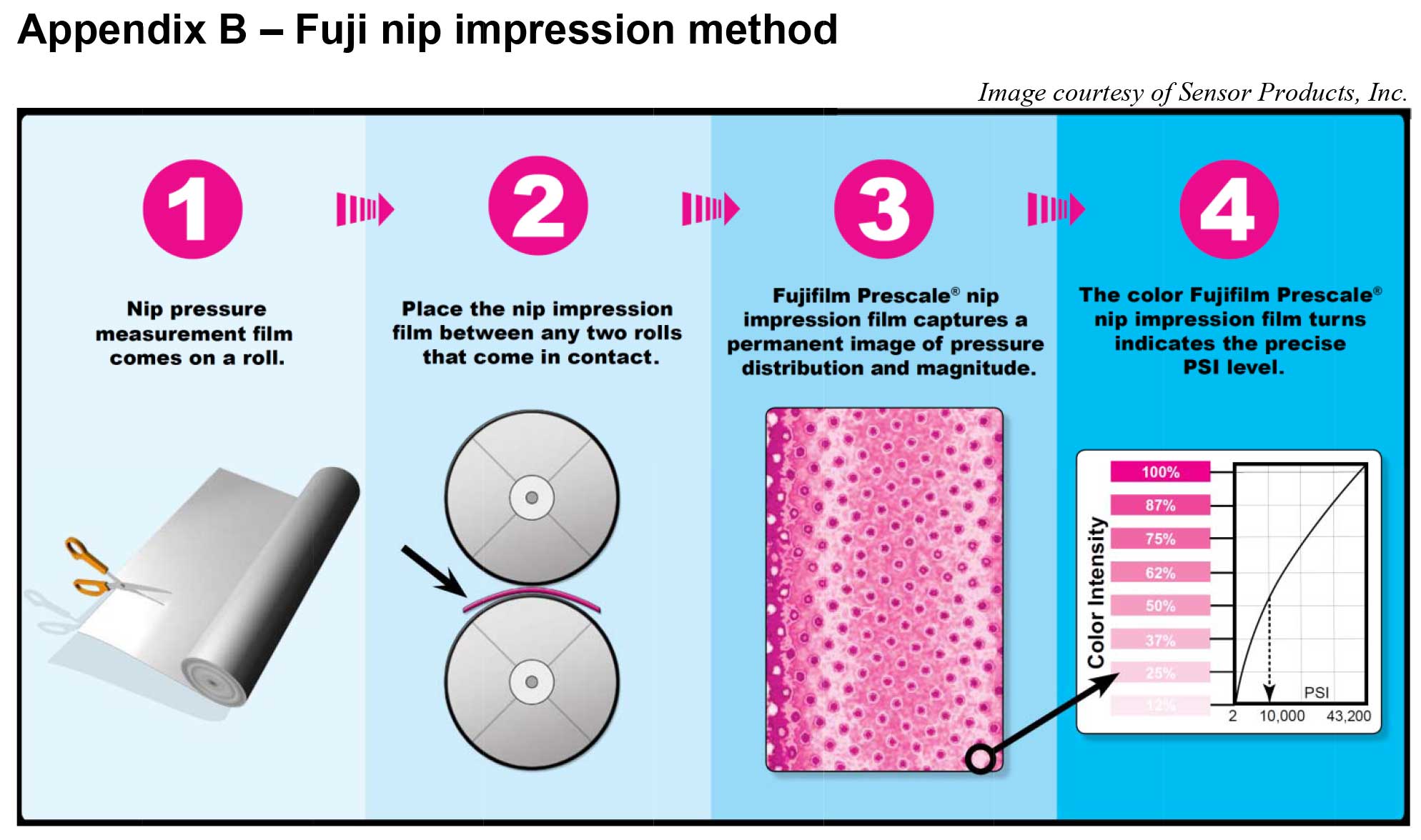
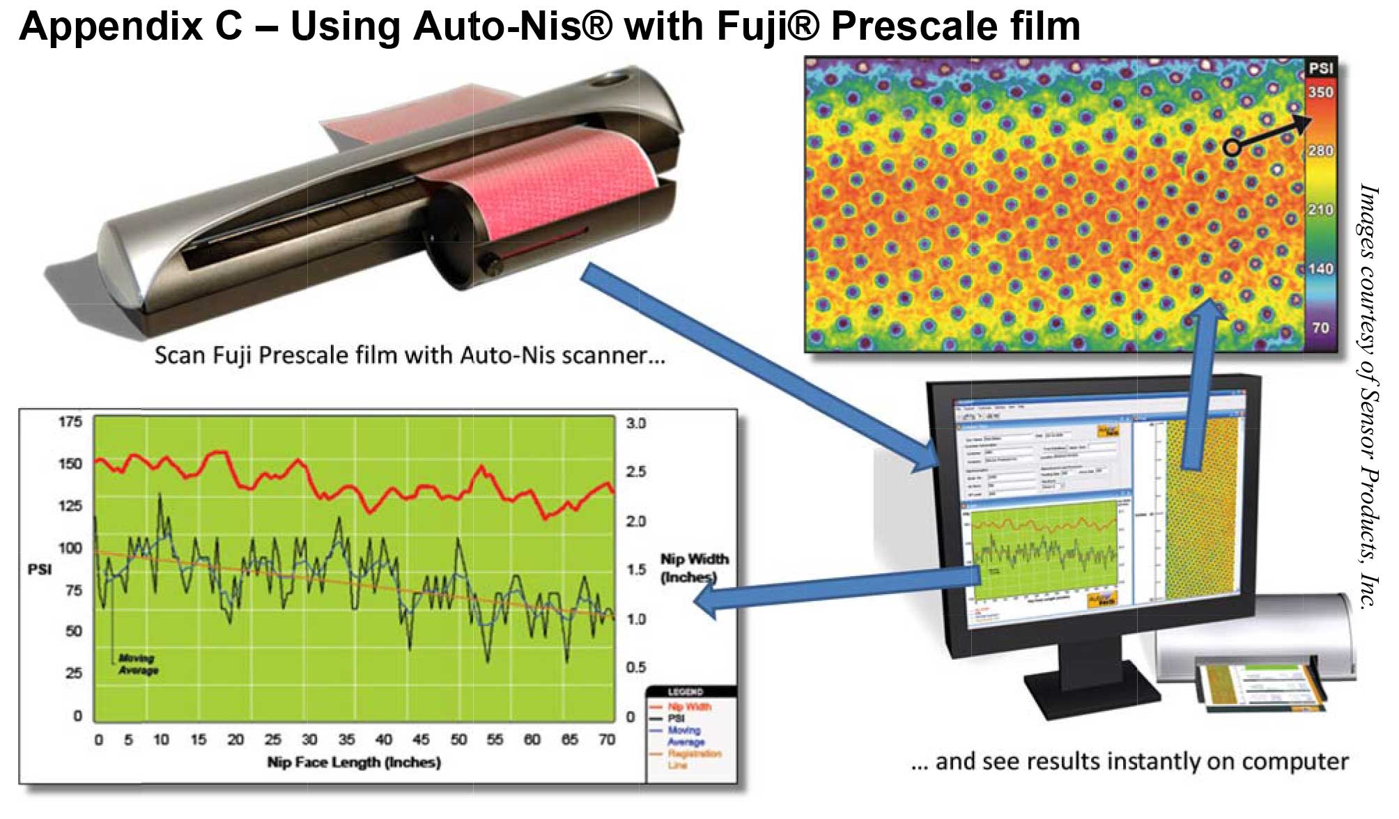
Fuji nip impressions are often called dynamic because they are performed while the rolls are loaded and in crawl. This test is performed by running pressure sensitive film (e.g. Fujifilm® Prescale nip impression film) through a closed nip. Depending on a pressure range in the load, different types of film must be ordered. Rather than measure nip width, the Fuji film test provides a pressure profile across the roll face of a press. The depth of color (usually red) in the film represents different pressures, the darker the color the higher the pressure imparted on the film at that cross directional point. Although a subjective evaluation of the Fuji film can be done with the eye to see what part of the press is loaded higher, to get actual values for the pressure a Fuji film reader must be used. A second method for measuring nip impressions with Fuji film is available. It can also be used in a static nip impression just as carbon paper, with widths measured accordingly. Fuji nip impressions give two advantages over carbon nips and electronic nips. First, they may give the best representation of what is going on in the nip if clothing must be left on the machine during the nip impression process. Second, they can be used in lightly loaded presses where carbon ip impression paper might not transfer. The disadvantage of the Fuji method is the delay in obtaining objective results due to the need to set up the Fuji film reader. The process of obtaining a Fuji film nip impression and using the reader are shown in Appendices B and C.
Other important parameters
At the time that the nip impression is made, two other parameters should also be determined. These are hardness and diameter profiles across the face of the two rolls. They are required to determine if the nip impression is being affected by wear or chemical softening and swelling. It will also verify the effects of crown or lack thereof on the nip impression. (For information on determining hardness, see Metso Technical Service Bulletin #25 “Measuring the Hardness of Covered Rolls (Plastometer Test)”.) Once this has been done, the nip impression can be analyzed.
Symmetrical load essential
The first step in analysis is to determine if the load was applied symmetrically. Symmetrical loading is essential for further quantitative analysis.
What we mean here is that the force applied to one end of the roll is the same as that applied to the other end. This can be checked very simply by folding the nip impression so that a comparison of the points 2″ in from each dub can be made visually. The same thing would be done for points which are ¼ of the roll face in from each end. If this visual comparison shows that the width of the impression at the corresponding points at each end is the same and the hardness and diameter profiles are symmetrical, then the load, presumably, has been applied symmetrically.
Extensive analysis possible
The application of a symmetrical load in itself is a highly important factor in the use of covered rolls and if the nip impression did nothing more than determine this, it would be a very useful tool. However, the nip impression can be used even further. One very useful area is determining whether the rolls have the proper crown.
Appendix D shows some schematic examples of typical nip impressions (these examples should be used as representations only). Examples No.2 and 3 show a condition of over-crowning and under-crowning respectively on symmetrically loaded rolls.
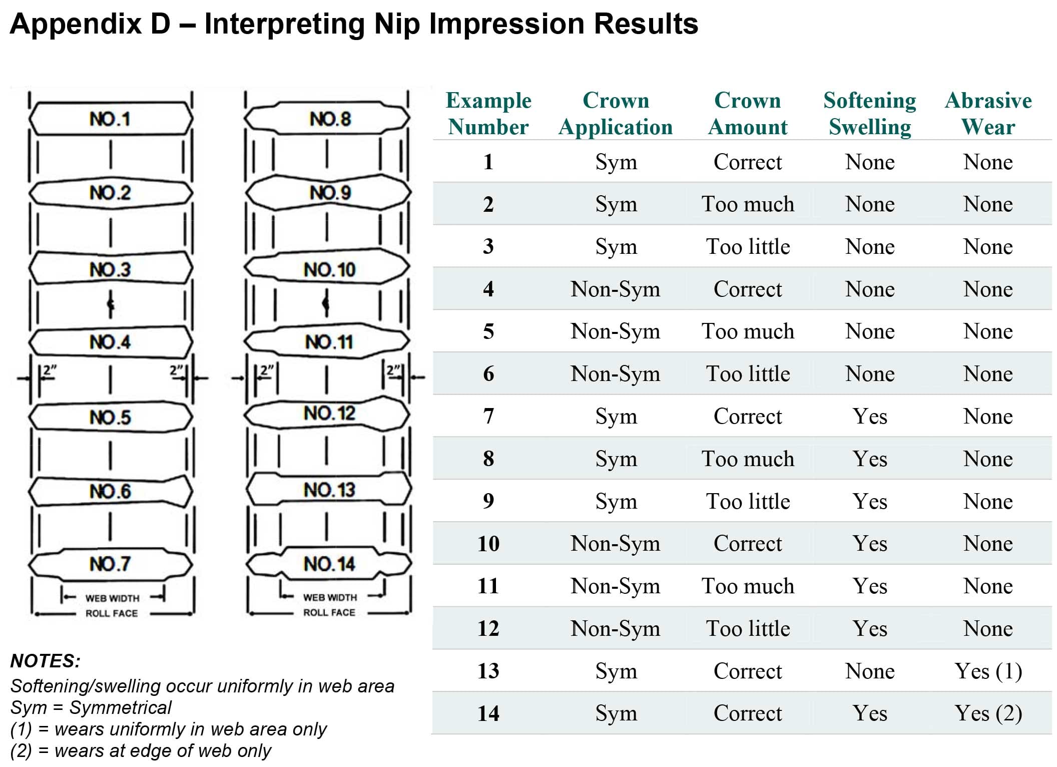
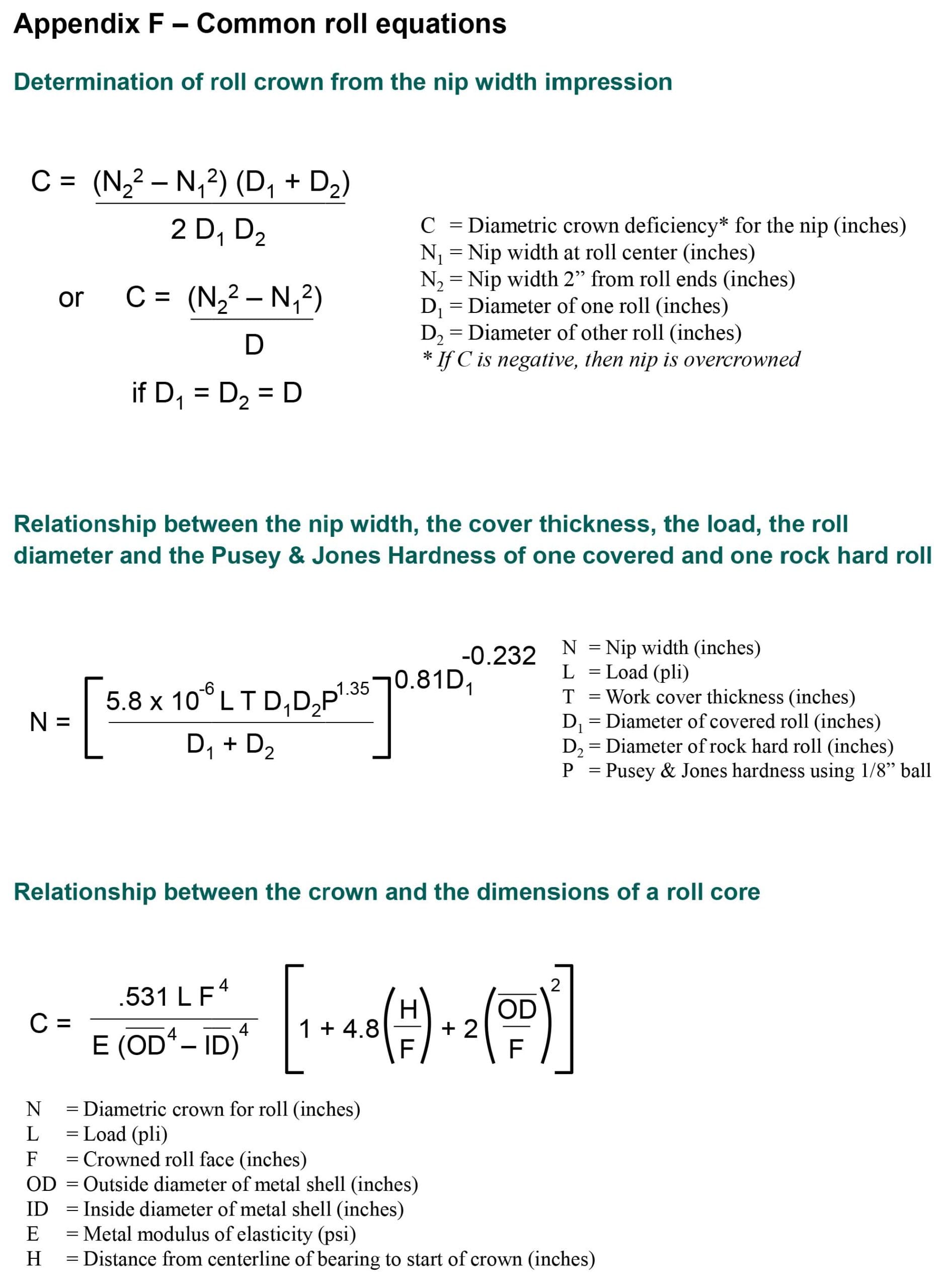
The amount of over and under-crowning can be determined when freshly ground or otherwise unaffected rolls are loaded symmetrically by measuring the nip width at the center of the impression and at a point 2″ in from either dub. This along with the diameters of the two mating rolls will allow a determination of the amount of this over or under-crowning through the use of Equation 1. Note: This equation is quite aggressive and in common practice it is often divided by 2.
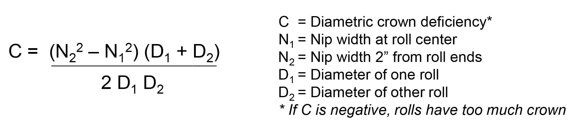
Equation 1. Crown calculation using nip widths and roll diameters
As an example let us assume that we have two 12-in. diameter rolls, and we find that the nip widths are 0.9-in. on the ends and 0.7-in. at the center under the loading at which we desire to run the rolls. Then by our formula, N1= 0.7, N2 = 0.9 and D = 12 and Equation 1 calculates as shown in Equation 2.
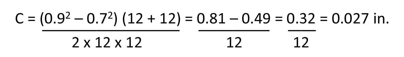
Equation 2. Crown calculation using Equation 1 with actual values for nip widths and roll diameters
If our rolls were originally ground straight face we would now put a crown of 0.027-in. into the rubber. If the crown were originally 0.030- n. it would be increased to 0.057-in. If the situation were reversed and the nip at the center (N1) were 0.9-in. and the nip at the ends (N2) were 0.7-in., our indicated crown would then be – 0.027-in. indicating that the nip already contained too much crown. Now if the crown of our roll were 0.030-in. then the proper crown would be 0.003-in.
If a symmetrical nip impression is obtained then the nip impression can also be used to determine or confirm conditions of wear or other abnormalities in the cover or core. It can even be used to indicate whether the proper type of crown was used or not. This involves how closely the crown contour accommodates the actual roll bending. This subject is discussed in more detail in the roll crowning section of this technical paper.
Optimize performance
It can now be seen that the nip impression is a very useful analytical tool for covered rolls. To obtain satisfactory performance in service, the force within the nip must be uniform. For the force to be uniform it must be symmetrical and the crown on the rolls must be sufficient to compensate for the bending of the roll bodies. Also, if too high a pressure is built up within one area of the nip the possibility of exceeding the acceptable mechanical stresses of the cover is present. For example, a nip might be nominally loaded to 300 PLI, but because of insufficient crown develop 100 PLI load in the center and 600 PLI at the ends. This type of abnormal loading profile affects sheet quality and also causes damage to roll covers and other equipment.
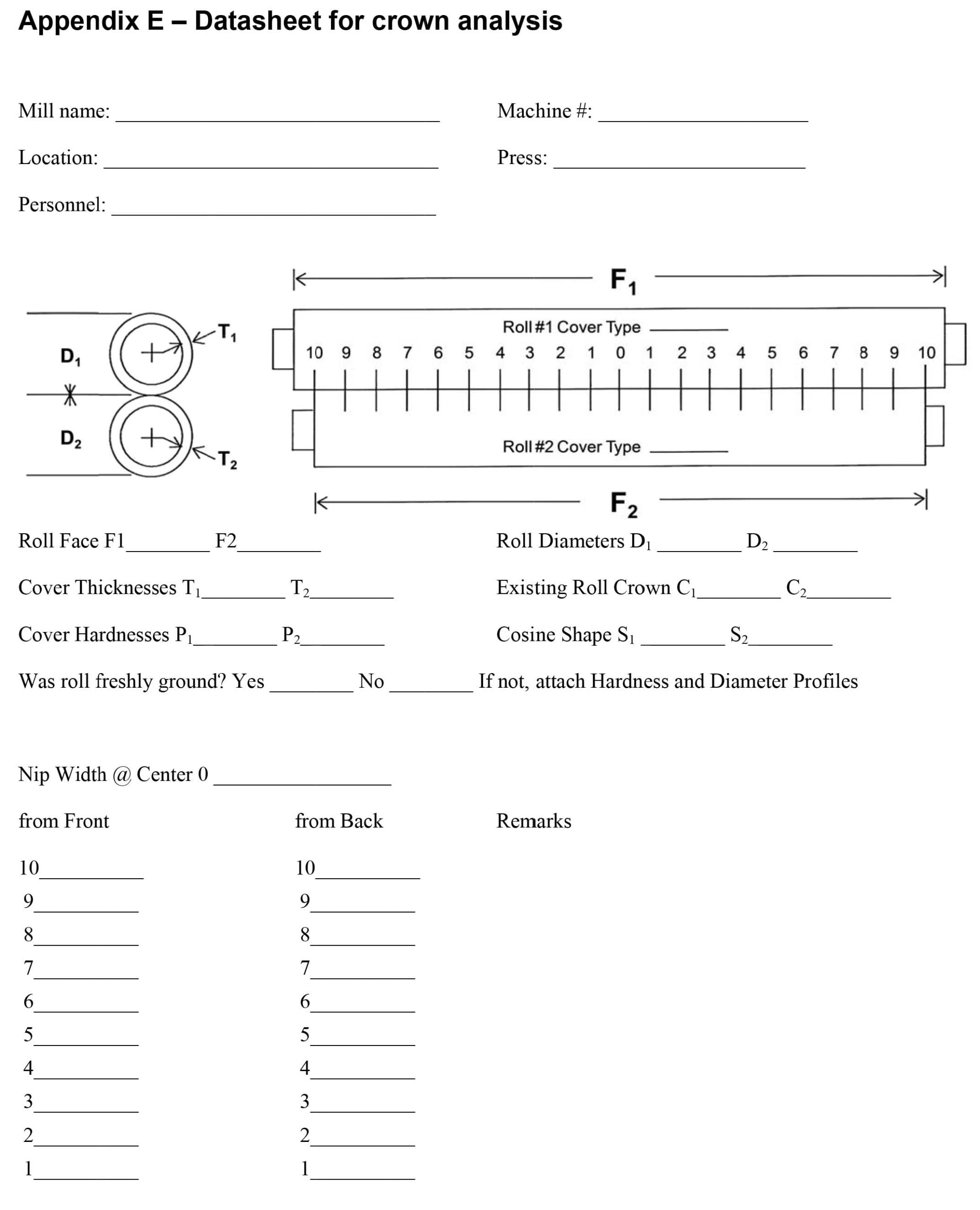
These factors and others can all be determined through the use of the nip impression and we recommend that before mating rolls are placed in service a nip impression be taken to insure proper load application. Although Metso covered rolls are of the highest quality, their performance is highly dependent upon the service conditions. Use of nip impressions can optimize this performance. For your convenience, Appendix E is a form designed to be used for the collection and recording of all the required data and for any crown analysis work to be done.
Roll crowning
The crown on a roll is simply a designed contour on the surface of the roll whereby the diameter (or radius) is continuously decreasing, non-linearly from the center point to both ends.
When two rolls are mated against each other with held journals and a force applied to the roll bodies, the rolls themselves are forced apart. The rolls actually bend away from each oth
er with the greatest amount of bending occurring at the center of the rolls. With covered rolls this is not readily noticeable and manifests itself in the form of a pressure gradient between the center of the roll and the ends. To compensate for this bending and the resultant pressure gradient, crowns are used.
Roll as a simple beam
Prediction of the amount of bending in a covered roll is made using versions of simple beam equations. To say that the covered roll performs like a simple beam is a highly misleading statement.
Factors such as non-uniform cross sections, unpredictable centers of gravity, areas of localized mechanical support, and non-uniform loading all contribute to deviation from simple beam equations. Theoretical equations could be devised to predict bending for each different roll configuration, but this would be highly laborious and an almost impossible task.
To date, this bending is being predicted by generalized forms of standard beam equations, which have been adjusted to compensate for shaft extensions and shear forces. This provides a very reasonable starting point for the determination of crown requirements.
Crown contours
Obtaining the proper degree of crown at the center of the roll is only part of the problem. The second part is obtaining the proper crown contour to match the bending of the roll at each point along the roll face. Present roll grinding equipment is designed to provide crown contours, which coincide with partial cosine curves as seen in Figure 2.
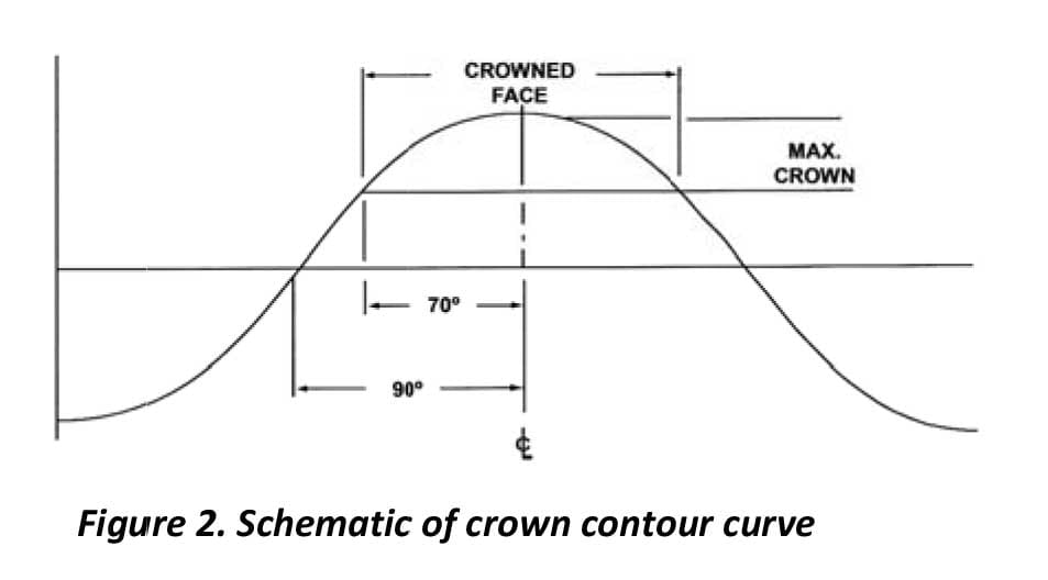
Figure 2. Schematic of crown contour curve
It can be seen that the crown contour or curve will be affected by three factors; the maximum crown in the center of the roll, the crowned face on the roll, and the degree of cosine crown used. Consequently, there is the possibility of providing numerous degrees of cosine crown and this enables the matching of the crown contour to the true deflection of the roll. Table 1 not only shows these factors for 70° to 120° cosine curves but also what they would be if they were developed using a standard beam equation.
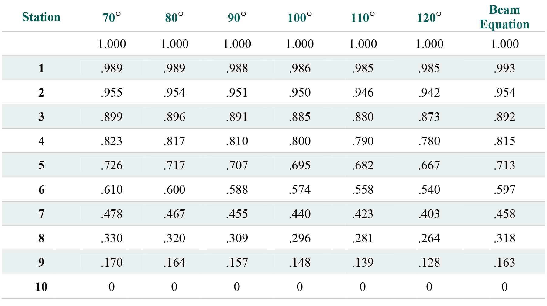
Table 1. Crown factors at 11 equally spaced points from the centerline to the end of the roll crown
It can be seen that at the center line and at station 10 which is the end of the crown on the roll, the factors are the same. At Metso, station 10 coincides with a point on the face of the roll 2″ in from the dub. The difference between the various cosine crowns lies between the center point and station 10. By inspecting this crown factor table it can be seen that the difference between the various cosine crowns is very subtle.
In order to gain a better appreciation of this difference we have plotted the crown factors for 70° and 120° cosine crowns versus the 10 stations along the roll face in Figure 3.
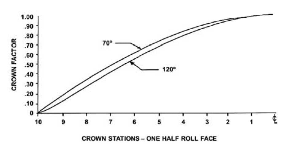
Figure 3. Difference between cosine crowns
It can be seen that the 120° cosine crown deviates considerably from the 70° cosine crown. At approximately the 1/4 point on the roll or station No. 6, the difference in the factor is .07. Based on a roll with a total crown in the center of .150″, this difference is equivalent to .010″. In other words there would be a difference in the amount of deflection at this point of .005″.
Although this may seem like a small and relatively insignificant amount, Table 2 will show that under certain circumstances, this amount of deformation difference can, in fact, be highly significant: In the table we show the load in PLI at various P&J hardness levels to attain deformations between .001″ and .005″. At the 5 P&J hardness level, the load differential equivalent to a .005″ cover deformation differential is 341 PLI.
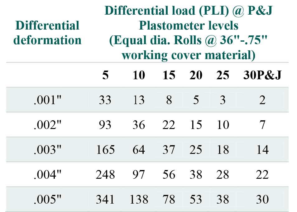
Table 2. Differential cover deformation (rubber)
Of course, as the cover becomes softer this differential becomes less, but even at 20 P&J we are talking about a significant 53 PLI difference, as seen in Table 2. Differences of this magnitude can result in highly unsatisfactory performance on the part of the covered roll, not only from the processor’s standpoint, but also from the covered roll manufacturer’s standpoint.
It now becomes apparent that not only is the total amount of crown on a roll important but the configuration of the crown contour as well. For most cases a proper amount of crown, contoured to a 70° cosine curve will be satisfactory. However, there are cases when it is not. As mentioned before, the bending of a covered roll under load is effected by a multitude of different variables, some adding to each other and some negating each other, with numerous combinations of variables in between. Consequently, the bending contour of the covered roll may not match a 70° cosine crown sufficiently to allow reasonable running of the roll in service.
Obtaining the proper crown
The attainment of a proper crown requires some trial and error. Without previous experience, a roll would be crowned with a 70° cosine curve to an amount dictated by modified beam deflection equations. Once this roll is put in service, however, a nip impression can be taken to determine the loading configuration on the roll. Depending on this loading configuration, corrective action, if necessary, can be taken. When corrective action is needed the proper crown quite possibly will not be attained even in the second attempt. Yet, within a few trials a sufficiently reasonable crown should be attained.
What is entailed in attaining this crown is first an analysis of a nip impression. If the nip impression shows a fairly uniform and non-linear taper from the center to the ends or from the ends to the center, the problem with crown would be that of too much or too little respectively. This can be corrected by determining the amount of under or over crowning thru the use of Equation 1 (stated earlier). The amount of crown differential arrived at with the use of this equation would then be either added to or subtracted from the present crown on the roll.
Other types of crown
There is another facet of crowning, which has gained moderate acceptance in recent years. This is the compound crown. It is basically a multiple crown designed to give additional relief to the ends of the roll. It differs from the straight dub or taper in the fact that the end relief actually has a normal crown contour and this end relief is usually further in from the end of the roll than a dub or taper. A diagrammatic profile for a compound crown is shown in Figure 3.
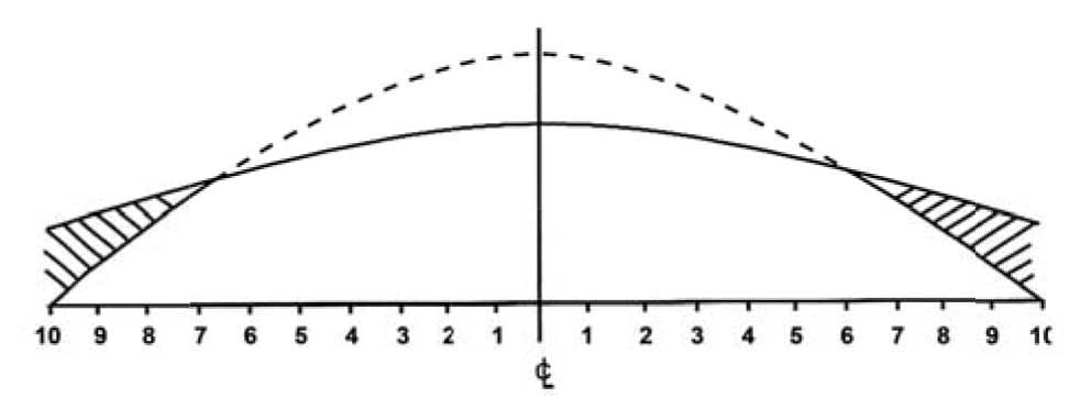
Figure 3. A diagrammatic profile for a compound crown
Here we show how a resultant compound crown is obtained. First, a gentle contoured crown is ground on the roll. Then a more drastic or steeper contour crown is imposed upon the first crown. The dotted curve shows the contour of the second crown, but indicates that it actually does not make contact with the roll surface in this area. The cross hatched area on the diagram is that area which is actually ground off when the second crown is imposed upon the first. The result is a roll surface with considerable relief at the ends. This relief is designed so that a gentle load application gradient will be obtained at these end areas.
Compound crowns have been used in areas where there is tendency
for very high load buildups at the ends of the rolls. An example of this would be a Yankee pressure roll where the covered roll running against the Yankee drum is subjected to high end loadings due to the design of the drum and the dynamic conditions at which it runs. Another area where compound crowns may be useful is with rolls where very long shaft extensions are encountered. It is not expected, however, to use a compound crown in most new applications. Usually, experience is needed in the service application. Compound crowning generally is a result of overloading problems at the ends of the roll and this may not be observed with static or carbon nip impressions. This would be the case for a Yankee pressure roll where the problem is dynamic. In the situations where a compound crown would be recommended from a nip impression, the nip width across most of the roll face is uniform and the nip will be wider on the ends. It is advisable to consult with Metso Roll Engineers before specifying compound crowns.
The roll does not stand alone
There is one other area on crowning of rolls that should be mentioned. Roll covers are crowned to compensate for the bending of the roll bodies themselves, and this bending is dependent upon a number of variables.
Among these variables is the press geometry. Whether it is aligned vertically, horizontally, or something in between is of great importance. Bending is load dependent and the total effective load on a roll includes weight and the resultant gravitational forces. For vertical presses, these gravitational forces are significant, for horizontal presses they are not. Also, in a vertical press there will be more bending of the rolls if the same external load is applied from the top rather than from the bottom. So when determining the amount of crown required, the whole press must be considered rather than an individual roll. This consideration will take into account such factors as roll alignment, load application, weight of the rolls, shaft extensions, magnitude of external loading and roll configurations.
The most appropriate source for crown recommendations is, of course, the machine builder, since they designed the press and the rolls. Also, the effect of the cover is insignificant in determining the crown requirement. It is only the vehicle in which the crown is applied to the roll. Metso can give assistance when crown problems arise. This assistance generally entails recommendations for increasing or decreasing the amount of crown. Sometimes it includes using a compound crown or possibly changing the type of crown with relation to the various cosine curves available. These recommendations are based on experience with the rolls in a specific application. All rolls will last longer and perform consistently when they are properly crowned. So, we make every effort to find the appropriate crown and improve our customers’ reliability.
Roll service problem solving tools
Papermaking consistently moves from an art form toward a science. Metso research and development, as well as the Metso service units, have served as pathfinders in this movement. Historically, the equations used most frequently by the roll service group have been for: determining roll crown; deflection; and relating nip widths to roll size and cover thickness. These equations can be found in Appendix F.
Today, in the age of technology, Metso not only uses the crown and deflection equations of the past, but has also introduced simulations for solving many problems faced by papermakers. Finite element analysis is used in NipSim software to determine nip dynamics. Metso uses PresSim to integrate theoretical calculations, as well as empirical values recorded from pilot machines to model changes in press performance based on manipulation of process inputs. PresSim can be used to predict press solid changes based on a scope as large as a press rebuild or on a scope as small as changing P&J on a press roll cover. FlowSim is a proprietary program which models water removal in a press and how custom drilling or grooving patterns can impact water balances. Finally, one of the most complicated problems for managing rolls can be scheduling and tracking history. Extending intervals between maintenance downs has great payback but it makes roll maintenance more challenging. Metso has developed a roll tracking database called RollTracer that can be used company wide.
NipSim – to determine nip dynamics
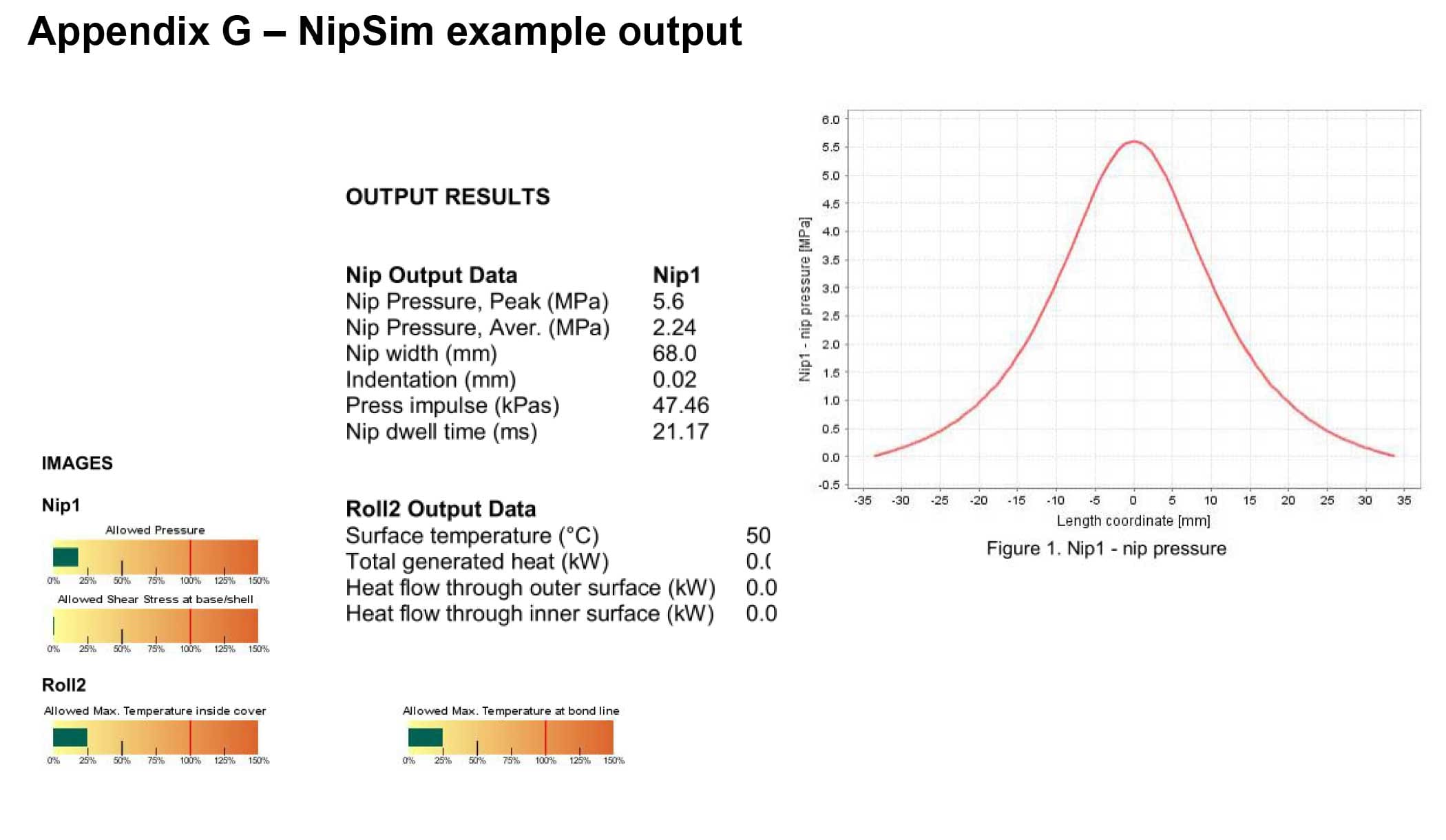
NipSim was developed in Finland by Metso research and development to model key operating parameters for cover compounds in the developmental stages. However, this program can also be used quite successfully by the technical service group to model the performance of covers under conditions of various mill applications. NipSim is widely used to determine water cooling needs for different cover applications and to assist finding a cover that can perform in certain applications without water cooling. It can also be used to determine standard nip values such as nip width, average or peak nip pressure, and press impulse. In addition, NipSim calculates nip displacement, radial and shear stress / strains. This conglomeration of data greatly assists in determining if a cover at a certain thickness is appropriate for a given application. On top of that, the information is presented in a format that is easily interpreted. An example of a NipSim output is listed in Appendix G.
PresSim – to model press roll cover changes
Like NipSim this program was not originally developed by the roll service group but has been found very useful in predicting the performance of covers in the press section. PresSim was developed to assist in finalizing the details of a brand new press section. By entering a list of predetermined process parameters, this program can predict the final press solids. For the press builder, if the water retention value and the couch solids can be given with press design, loads and roll cover selections, then PresSim can determine the final press solids.
For the cover manufacturer, the press already exists but changes to the cover material, hardness, and surface finish (or open area) can be modeled to determine the impact on press solids and production. Examples of both the needed inputs for this program and the results generated by this program are attached in Appendices H and I.
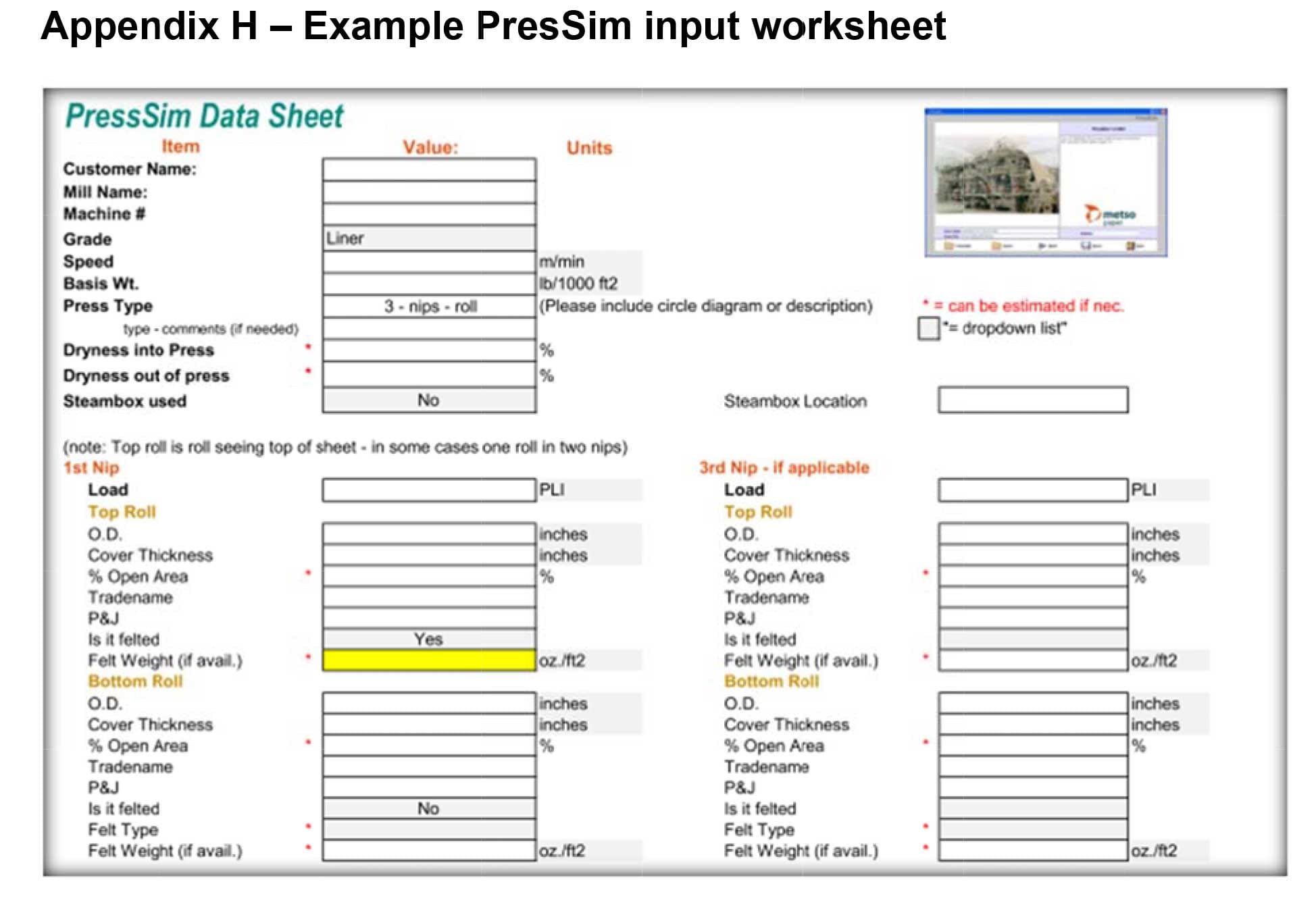
The PresSim tool is now used widely by the Metso technical service group. It is used for mills under Metso roll program agreements to look at alternatives for what is currently being run in the press. It can also show potential customers how a Metso cover may perform in comparison to a competitor’s cover.
FlowSim – to determine drilling and grooving effectiveness
FlowSim was developed by the roll service group to model the effects of roll properties on water removal in a press section. FlowSim uses and requires many of the same inputs as PresSim, but it requires and models the results using more detail around custom roll surface finishing. Where PresSim requires a roll surface open area, FlowSim requires a complete detail of the roll’s surface, including custom drilling and grooving patterns. Therefore, it not only calculates press solids but also total void volume in the press. This level of detail allows the calculation of the minimum distance water must travel to reach voids in the cover and details such as water splits between top and bottom felts, pan flows, uhle flows, etc. FlowSim also includes payback and ROI calculators to help justify cover changes. Examples of FlowSim outputs are ava
ilable in Appendix J.
RollTracer – roll tracking database
RollTracer is not a calculation or a simulation. It is simply an easily accessible, web-based database that allows tracking roll history and scheduling roll changes. This tool breaks down the machine into manageable sections. Once a roll is named and either installed in the machine or placed into roll storage, the events that occur for that specific roll can be uploaded into the database. This includes maintenance such as grinds, reconditions, or recovers and provides a platform for storing service summaries, bearing reports, roll specs, out-crowns and much more.
For events that actually make up a run cycle in the machine, either installing a roll or removing a roll, RollTracer creates automatic run histories that can be queried by roll name or by machine position. The amount and types of information that can be stored by machine and roll are virtually limitless. RollTracer can store drawings, inspection reports, real time information about roll conditions in the machine, old sales orders, and spares information (see examples in Appendix K). Finally, for the dedicated user, if RollTracer is updated regularly for approximately 3-4 years, it becomes an integral tool for developing roll repair budgets. In fact, there is a budgeting tool in the program to assist in this process as long as roll information is up to date.
Summary
Metso developments include new roll covers and increasingly complex computer-driven calculations for modeling of roll dynamics, grooving and drilling, and nip mechanics, as well as a roll tracking database system. Calculation of the correct crown and interpretation of the nip impression are often repeated and yet easily misunderstood procedures, requiring the necessary calculations and tools. This white paper combines technical information obtained from published Metso articles and papers.
Metso is a global supplier of technology and services to customers in the process industries, including mining, construction, pulp and paper, power, and oil and gas. Our 30,000 professionals based in over 50 countries deliver sustainability and profitability to customers worldwide. Expect results.
![]()