by A.B. Liggins and J.B. Finlay
Fuji Prescale pressure-sensitive film (Fuji Photo Film Co., Ltd., Tokyo, Japan) allows pressures between 0.2 and 130 MPa to be recorded, using five film grades (ultra-super-low, super-low, low, medium and high); each grade covers a different pressure range. With the exception of high-grade film, Fuji film is supplied in two sheets (the A- and C-films); interface pressure causes fluids to be released from microscopic bubbles on the surface of the Afilm. which react with an active layer on the surface of the C-film to produce a pink stain.1,2 For high-grade film, the Aand C-film materials are superimposed on the surface of a single sheet. For pressures between the upper and lower threshold-values. the optical density response of the film can be calibrated with respect to the applied pressure.1,2 It should be noted that the optical-density response of Fuji film is also temperature-, humidity- and load-rate dependent; these factors have been discussed previously.2
The manufacturer provides calibration charts and color samples, which can be used to convert optical-density readings into pressure; these readings are made either visually, or via an (optional) optical densitometer (article# FPO 301). The limitations of this approach1 have prompted the development of digital imaging techniques, both to calibrate Fuji film response (for temperature, humidity and load-rate effects) and then to convert subsequent test-stains into full-field pressuremaps.1,3-6
In our previously described technique,1-6 25.4-mmdiameter calibration stains are produced between two finely ground, hardened-steel surfaces. Loads are applied using an MTS 858 Bionix universal testing machine (MTS Systems Corporation, Eden Prairie, MN) giving a one-minute linear (± 0.1%) ramp up to full load, followed by a one minute hold at that load (± 1 N, i.e. ± 2 kPa applied-pressure) and a oneminUet: linear ramp down to the original (10 N) pre-load. Following the subsequent experimental procedure for obtaining test stains from an interface of interest. a digital image of each (calibration and test) stain is captured via a CCO video camera and a ‘PC’ computer running ImagePro Plus software (Media Cybernetics. Silver Spring, MO). This approach results in grey-scale images consisting of O.l-mm-wide X 0.08- mm-high pixels, each having a value between 0 (representing ‘black’) and 255 (representing ‘white’);6 data from the calibration stains are used to produce a fifth-order polynomial relationship between pixel-value and applied-pressure.1,6
To produce a false-color pressure map from the test stains, the working pressure range (between the upper and lower thresholds of pressure response) is divided into a number of pressure intervals; 1.6 each of these intervals is given a unique representative color. For each pixel on a test-stain image, its value is used (via the fifth-order calibration relationship) to determine the pressure at that point; the pixel is then rewritten to the color corresponding to the pressure interval within which the calculated pressure lies.1,6
The object of this study was to quantify the effects of an image-enhancement protocol on the resolution properrties of pressure maps produced in this manner.
Resolution Properties of Pressure Maps
The burst-bubble mechanism used by Fuji film results in stains composed of discrete patches of red coloration (Fig. 1 );7 consequently, calibration-stain images consist of a range of pixel values, representing the single pressure at which the stain was obtained. As a result, there is a limit to the number of meaningful pressure intervals that can be represented on any pressure map.b A previous study analyzed groups of six calibration stains taken at each of four nominal pressures across the working range of super-low Fuji film6. It was found that a practical definition of pressure intervals could be determined from Mo ± Sp where Mo was the overall mean pixel value for a group of six calibration stains and Sp was the pooled standard deviation for that population.8 Applying the fifth-order calibration relationship I to this range of pixel values resulted in the characteristic pressure range Rp, for each population; the values of Rp were sub~quently used to define the size of valid pressure intervals across the working pressure range of the film. From this definition, reducing Sp would result in a reduction in Rp, and hence produce a finer pressure interval; thus, pressure resolution would increase due to an increased number of pressure intervals which could fit within the film’s working pressure range. It was shown that this effect could be achieved by increasing the sample area size used to acquire pixel-value data across the stain image.6 Therefore, it was concluded that the production of false-color pressure maps is a compromise between pressure and spatial resolution. One-pixel square (O.l-mm wide X 0.08-mm high) sample areas only provided four identifiable pressure intervals across the valid pressure range of super-low film;6 hence, when used in this manner, Fuji film appeared to be of limited use for small contact areas, or those subjected to high pressure gradients.
Image Averaging
A standard image-enhancement technique for noisy images is to define the value of each pixel on a resultant image as being the average value obtained from corresponding pixels on several positionally registered (noisy) images of the same object9 as the number of constituent-images increases, the effect of noise approaches zero, such that a ‘clean’ image is created. Similarly, it can be envisaged that this ‘image-averaging’ method would reduce the effect of the random granularity observed on Fuji film stains (Fig. 1), thereby reducing Sp (see above) and increasing pressure resolution, for any given spatial resolution.6
Hale and Brown7 demonstrated that averaging data from a number of transverse contact-stress profiles (each representing the same one-dimensional stress di stribution) will result in a noticeable reduction in noise caused by pixel-value fluctuations; however, the degree of data enhancement was not quantified. In addition, preliminary (qualitative) results from Liggins et al.1O have shown that full·field (i.e. two-dimensional) image-averaging will reduce the effects of random stain-disruption caused by sealing Fuji film to prevent fluid damage.
Consequently, the following work was conducted to quantify the full-field effects of image addition on pressure resolution. in terms of the number of valid pressure intervals (colors) which could be used for a subsequent false-color pressure map.6
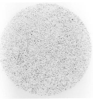
Fig. 1 – A typical 25-4-mm-diameter Fuji film calibraUon stain, produced at 1.0 MPa
Experimental Procedure
Twelve standard calibration stains were produced from super-low Fuji film. at pressures between 0.26 and 2.97 MPa, using the method described in the introduction .1.6 Six ‘test’ calibration stains (i.e,. identical to standard calibration stains) were then obtained for each of four nominal pressures (0.5. 1.0, 1.77 and 2.5 MPa). using the same loading protocol; for each pressure. the corresponding stains were each given a reference number from one to si :(. Following a 50-hour ‘development period’, a digital image of each stain was captured as described above.1,2,6 The 12 calibration-stain images provided data for the cal culation of a fifth-order rebt ionship between pressure and pixel-value, using SigmaPlot software (Jande I Scientific. Cone Madera, CA). The remaining test stains were subjected to the following protocol.
A 190-pixel-square ‘area of interest’ (AOI) was defincd within each stain: this size of AOI correspond ed with that used for both obtaining daln from calibration-stains1 and for previous investigations of Fuji film propcnies.6,10,11 A previously described, custom- written, computer program6 was used to read the value of each pixel within the AOI and store these data to a file. A simple random-number generator. written in Quick Basic (Microsoft Corporation. Redmond. WA) was used to determine me order of file combination, For each set of six stains (i.e., at each of the four nominal pressures). six groups of stain reference numbers were chosen; each group consisted of five (different) numbers between one and six, indicating the order of addition of the corresponding data flies (Fig. 2). A second computer program was custom written in the ‘C’ programming language to combine and average the pixel values within the data files, according to these groups of random numbers. If N was the number of images 10 be combined, then the program loaded the data files corresponding to the first N numbers within the given group of five (Fig. 2); as data within these files were traversed, the N pixel values corresponding to a given spatial position (on the image) were added and the result divided by N, prior to being stored in a new data fi le. Once the new data file was complete. a mean and standard deviation for the data of this resultant image were calculated. Therefore, for each nominal pressure, this procedure resulted in five sets of six data files, where each set contained resultant images consisting of the same number (one. two, three. four or five) of individual stain images (for a total of 30 data files at each nominal pressure).
For each population of six resultant images (i.e .. at a given nominal pressure and number of combined stains) the overall mean pixel value, Mo, was calculated as the mean of the six individual mean pixel values; similarly. an overall standard deviation for the population. Sp. was calculated using the method of ‘pooled variance’8. The pixel values given by Mo ± Sp, were used to calculate the characteristic pressure range. Rp, for the population6 these pressure intervals were subsequently used to determine valid pressure intervals for each number of combined stain images (one to five).6
Results
Figure 3 shows the fifth-order calibration curve produced from the 12 standard calibration stains. Figures 4 and 5 show the overall standard deviation for the population (Sp) and the pressure range (Rp) calculated from Mo ± Sp, respectively, against the number of constituent stain images (N). Table I shows the suggested pressure intervals (I1 – I8) for each value of N, as determined from the values of Rp.
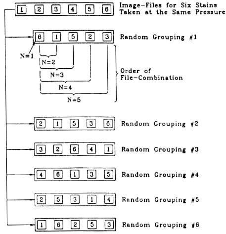
Fig. 2 – Image-file selection for the production of resultant-image files from N constituent images
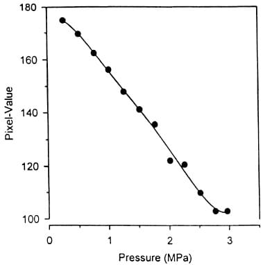
Fig. 3 – Fifth-order polynomial curve-fit for twelve standard calibration stains, using superlow Fuji film at 25°C and 45% relative humidity
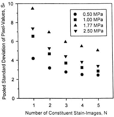
Fig. 4 – Pooled standard deviation of pixel-values (Sp) against number of constituent stain images (N) for stains taken at 0.5, 1.0, 1.77 and 2.5 MPa applied pressure
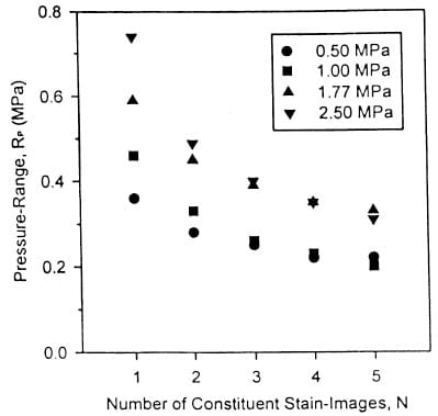
Fig. 5 – Characteristic pressure-range (Rp) against number of constituent stain-images (N) for stains taken at 0.5, 1.0, 1.77 and 2.5 MPa applied pressure
Discussion
As expected, combining stain images results in a progressive reduction in Sp, and hence Rp (Figs. 4 and 5); surprisingly, the pressure intervals determined from these results (Table 1) suggest a simple (and convenient) general relationship whereby each additional stain image forming the resultant image will provide an additional valid pressure interval. It should be noted that while Sp is greater at 1.77 MPa than at 2.5 MPa (Fig. 4), in some cases Rp has a higher value at 2.5 MPa (Fig. 5). This seemingly unusual result is due to the decreasing gradient of the calibration curve as the stain response approaches saturation, and the corresponding pixel value approaches a constant (Fig. 3); hence, smaller changes in pixel value will represent larger changes in pressure at this end of the calibration curve.
The optical density of Fuji film stains has been shown to be dependent on the temperature and humidity at which the stains are produced.1.1 The stains used for this work were obtained at a mean (± SD) temperature of 25.4 ± O.2°C and a mean (± SD) relative humidity of 45.3 ± 2.6 percent; further analyses are required to assess the influence of these factors on image-addition characteristics. Similarly, these results were obtained using super-low grade Fuji film and additional experiments are required to assess the effect of this procedure on stain-images from the remaining film-grades (ultra-super-low, low, medium and high); however, due to the similar stain-forming mechanism on each film-grade, similar image-addition characteristics would be expected.
Table I shows that, for example, the combination of five stain images provides eight pressure intervals for a one-pixel-square (O.1-mm-wide X O.08-mm-high) sample-area; this pressureresolution is equivalent to that,possible from a single stain image when a 2-mm-square sample-area is employed.6 Therefore, the image-addition technique provides a significant improvement in the spatial- and pressure-resolutions of subsequent pressure maps; however, this approach relies on the correct positional registration of stain images,9 which may lead to practical difficulties. To achieve this requirement, each stain can be placed at the same position under the video camera (or on the scanning device); alternatively, the associated image-processing software can be used to align each captured stain image as required. In either case, some form of (accurate) ‘indexing’ method is necessary to identify the position and alignment of the stain, thereby allowing accurate registration of each stain. The use of shape-recognition algorithms may be impractical; the granular nature of Fuji film stains
can result in difficulties when attempting to define the outline of any particular stain to the accuracy required.2 A more realistic approach is to place a series of index marks on the film during loading, such that the film’s position (and hence that of the subsequent stain) is defined relative to the interface within which it is being loaded; these marks should be as small as possible (ideally. equivalent to one pixel on the stain image). for accurate determination of their positions. Index marks can be created on Fuji film placed within a human or animal articulating joint via holes drilled through one of the bones forming the joint; during loading. a wire or needle is pushed through each hole such that a small pressure stain is produced on the film.12 These holes are arranged such that the resulting index marks are away from the contact area and. therefore. do not interfere with the subsequent interface pressure data. Alternatively. the outline of one of the contacting surfaces may be traced onto the Fuji film (using a sharp indentor). during loading;2 this method will only be valid if there is little gap between the surfaces at the periphery. thereby allowing accurate placement of the indentor.
Clearly, there are many potential solutions (and problems) associated with the practical addition of Fuji film stain-images; the appropriate solution will be largely dependent on the characteristics of the interface under investigation and the facilities available on the image-processing software which is being used.

TABLE 1 – SUGGESTED PRESSURE-INTERVALS, I (MPa), FOR THE ADDITION OF N STAIN-IMAGES WITH “SUPER LOW” FUJI FILM
Image addition is a useful tool for detennining interface pressures in situations demanding greater spatial and pressure resolution than those resolutions possible from the analysis of a single stain image; such interfaces include those consisting of a small contact area, or those experiencing high pressure gradients.
Conclusion
References
- Liggins. A.B., Stranart. J.C.E. Finlay, J.B. and Rorabeck. c.H. “Calibration and Manipulation of Data from Fuji Pressure-sensitive Film.” Experimental Mechanics: Technology Transfer between High Tech Engineering and Biomechanics. ed. E.G. Little, Elsevier Science Publishers, Amsterdam, 61-70 (1992).
- Liggins. A.B. and Finlay. J.B. “Recording Contact Areas and Pressures in Joint Interfaces.” Experimental Mechanics: Technology Transfer Between High Tech Engineering and Biomechanics. ed. E.G. Little. Elsevier Science Publishers, Amsterdam. 71-88 (1992).
- Brown. TD, Pope. D.F., Hale. J.E., Buckwater. JA. and Brand. R.A. “Effects of Osteochondral Defect Size on Cartilage Contact Stress.” J. Orthop. Res. 9 (4). 559-567 (1991).
- Hehne. H.J., Haberland. H,. Hultzsch, W. and Jantz, W. “Measurements of Two Dimensional Pressure Distributions and Contact Areas of a Joint Using a Prrssure-Sensitive Foil,” Biomechanics: Principles and Applications, eds. R. Huiskes, D.H. Van Campen and J.R. De Wijn, Martinus Nijhoff, The Hague. 197-203 (1982).
- Wagner. V.A,. Sallgeorzan. B.J., Harrington. R.M. (/lid Tencer. AF.. “Colltact Characteristics of the Sub/(llar Joint: Load Distribution BeMeen the Anterior and Posterior Facets.” l Orthop. Res. 10 (4). 535-543 (1992).
- Liggins, A.B., Hardie. WR. and Finlay, J.B., “The Spatial and Pressure Resolution of Fuji Pressure-sensitive Film,” EXPERIMENTAL MECHANICS IN PRESS.
- Hale, J.E. and Brown, T.D., “Contact Stress Gradient Detection Limits 0f Pressensor Film.” J. Biomechanical Eng., 114 (3), 352-357 (/992).
- Wonnacott, TH and Wonnacott, R.J., Introductory Statistics, John Wiley and Sons, Toronto, 5th ed,. 266 (1990).
- Gonzalez, R.C. and Woods. R.E., “Image Enhancement.” Digital Image Processing. Addison- Wesley Publishing Co., Reading, MA. 187-188 (1992).
- Liggins, AB,. Surry, K. and Finaly, J.B., “Sealing Fuji Prescale Pressure- sensitive Film for Protection Against Fluid Damage: The Effect on its Response,” Strain. IN PRESS.
- Liggins, AB., Hardie. WR. and Finlay. JB., “Sterilization of Fuji Pressure-sensitive Film.” Med. Eng. Phys., 16 (6), 496-500 (1994).
- Marder, R.A., Swanson. T.V., Sharkey,. N.A. and Duwelius. P.J., “Ef/ ects of Partial Patellectomy and Reattachment of the Patellar Tendon on Patellofemoral Contact Areas and Pressures,” J. Bone and Joint Surg, 75A (I). 35-45 (1993).


