

Article
Related Links
Sen-Yeu Yang *, Fang-Sung Cheng, Shu-Wen Xu, Po-Hsun Huang, Tzu-Chien Huang
Department of Mechanical Engineering, National Taiwan University, Taipei 106, Taiwan
Abstract
The conformal contact between the roller stamper and the thin flexible substrate is important for precisive replication of microstructures. In this study, we have proposed a novel mechanism which employs a soft roller stamper and a gas-pressurized platform to fabricate UV-cured polymeric microlens arrays on a continuous flexible substrate. The new facilities constructed in this study comprise a polydimethylsiloxane (PDMS) stamping roller, a gas-pressurized platform and an UV light source underneath the platform. The soft roller was made by casting a pre-polymer of PDMS in a plastic master of microlens array. During the rolling micro-stamping process, the microlens array cavity on the soft roller is first filled with liquid UV-curable resin. The roller stamper then rolls and stamps over the moving transparent thin polymeric substrate which is located on the gas-pressurized platform. At the same time, the UV light irradiates beneath the platform and cures the resin in the rolling zone. Thus, the microlens array patterns are successfully fabricated. The dimensions of the microlens are 115.5 lm in diameter, of, a sag height of 7.88 lm in sag height, and 200 lm in pitch size. This method developed in this work clearly demonstrates its potential of using the soft mold and the gas-pressurized platform for continuous mass production of films with microstructural patterns.
Keywords: Soft roller; Gas-pressurized platform; Microlens array; UV-curable resin
1. Introduction
Microlens array has become an important optical component used in many applications such as flat panel display, micro-scanning system, fiber coupling, optical data storage and optical communication. Many methods for the fabrication of microlens arrays have been reported, e.g., including photoresist reflow method [1,2], UV proximity printing [3], excimer laser ablation [4], gray scale photolithography [5], microjet fabrication [6] etc. Most of these methods involve complicated process and require expensive equipments. For a low-cost mass production, replication of microstructures unto polymeric material is the most effective approach. Replication processes, such as injection molding [7] and hot embossing [8], have been developed. However, they involve high temperature, high pressure and are time-consuming batch-wise processes.
Among polymer processing methods, rolling is a continuous and efficient process. We have reported a rolling embossing process, which replicated microstructures from a Ni roller mold to the resin on glass substrates [9]. Furthermore, a soft roller stamping process with UV-curable polymer for fabrication of microlens arrays on glass substrates has been demonstrated [10]. In the above methods, the roller is pressing and moving the glass substrate, while the microlens array patterns on the roller are transferred to the UV-curable resin coated on the glass substrate. They are cured by the UV light radiation. Although this technique is effective, the process is difficult to extend to thin polymeric substrate due to the difficulty of maintaining the required conformal contact and uniform pressure between the soft roller and the thin film. To solve these problems, a roller stamping process with a soft mold and a gas-pressurized platform is proposed in this study. The design is aimed to provide conformal contact and uniform pressure between the soft roller and flexible polymeric substrate while transferring the UV-curable resin from the mold cavity onto the substrate.
In this study, a roller stamping system with a soft mold, a gas-pressurized platform and an UV exposure capacity has been designed, implemented and tested. The replication quality, surface roughness and optical property of the replicated microlens arrays have been measured and verified.
2. Experimental setup
2.1. Preparation of the soft roller with microlens array cavity
As shown in Fig. 1a, the plastic master with microlens array is first fabricated by gas-assisted hot embossing technique. The microlens array is formed when a heated polycarbonate (PC) film (Lexan8010, GE, USA) of 178 &um;m thickness was pressed onto a silicon mold with micro-holes array [11]. The shape, height and diameter of the microlens array were measured by a surface profiler (Alpha-Step 500, TENCOR, USA) and inspected by scanning electron microscopy (S-3000H, Hitachi, Japan). Fig. 1b and c shows the SEM image of the fabricated PC microlens array and its surface profile. The microlens array on PC film has a diameter of 115.5 &um;m, a pitch of 200 lm and a sag height of 8.0 &um;m.
Fig. 2 illustrates the procedure for fabrication of a soft roller with microlens array cavity [10]. The microlens array on PC film as the master mold is directly wrapped onto a cylinder as shown in Fig. 2 to form a roller with shallow shell cavity. Then the viscous polydimethylsiloxane (PDMS) pre-polymer solution (SYLGARD 184, Dow Corning, USA) is poured into the shell cavity formed. After the pre-polymer being cured, the PC film was peeled off from the PDMS. A soft PDMS roller with microlens array cavity is obtained. The measured diameter, pitch and sag height of microlens array cavity on the PDMS roller are 115.5 &um;m, 200 &um;m and 8.0 &um;m, respectively. The soft roller with microstructure cavity has been successfully prepared.
2.2. The rolling stamping facility and process
Fig. 3 shows the construction of a rolling stamping system with gas-pressurized platform and an UV exposure capacity. The system is composed of a UV-lamp, a transparent substrate, a soft PDMS roller stamper with microlens array cavity, a slit coating module, a flexible platform with gas-pressurized pad, and a couple of pneumatic cylinders. The UV-lamp (UV-A365, Philips) has a power of 400 W/cm2 and a wavelength range of 365–410 nm. A polyethylene terephthalate (PET) film (A-type, NAN YA, Taiwan) with a thickness of 180 &um;m is used as the flexible– transparent substrate. The flexible platform consists of a frame made of aluminum alloy, a soft pad of 1 mm thick, and a bottom plate made of optical-grade PMMA. The soft pad is made of a polyvinyl chloride (PVC) film, which can deform when it is pressurized by the nitrogen gas. The gas pressure is between 0.01 and 0.04 kgf/cm2. The flexible platform with gas-pressurized soft pad assures the PET substrates in conformal contact with soft roller. The maximum rolling speed is 2.5 mm/s. The pneumatic cylinders apply a constant stamping pressure during the rolling micro-stamping process. The pressure of pneumatic cylinder is between 0.4 and 0.8 kgf/c
m2. The slit coating module is used to coat the ultraviolet-curable resin onto the soft PDMS roller stamper. The coating thickness can be adjusted by varying the moving speed of the platform. An ultraviolet-curable resin (UV1321, CHEM-MAT, USA) with a refractive index of 1.5027 and a viscosity of 2500 cps at 25 °C is used is employed.
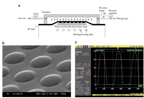
Fig. 1. Fabrication of PC microlens array master using gas-assisted hot embossing. (a) Schematic showing the gas-assisted hot embossing facility and process (b) SEM image of the PC microlens array (c) surface profile of the PC microlens array.
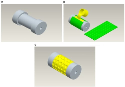
Fig. 2. Fabrication procedures of soft roller stamper with microlens array cavity. (a) Aluminum alloy cylinder without micro-features (b) PDMS casting (c) soft roller with microlens array cavity.
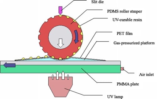
Fig. 3. Schematic showing the soft roller stamping system with gas-pressurized platform.
The soft roller stamping process is composed of three steps:
- The UV-curable liquid resin is coated onto the soft roller with microlens array cavity by the slit coating die. The excess material is removed by a scraper.
- The UV-curable resist coated in the microlens array cavity of soft roller is brought into contact with the PET film by applying a specific pressure.
- The liquid resin is transferred onto the PET film and is cured by the UV irradiation during rolling. Thus, the PET film with microlens array is obtained.
3. Results and discussion
3.1. Stamping pressure distribution with gas-pressurized platform
To investigate the stamping pressure distribution during a soft roller stamping with gas-pressurized platform, a prescale film (LLW, Fuji, Japan) with a pressure measurement range from 0.01 to 0.5 MPa was employed. The prescale film is composed of microcapsules and color developing layer. The pressure applied on the film breaks its microcapsules. As a result, the local density of broken microcapsules is determined by the local pressure, and results in color intensity on the film. The color intensity can be calibrated to the contact pressure, with 10% of accuracy. Fig. 4 shows the pressure distribution as displayed on the pressure-sensitive film using this stamping system with a flexible gas-pressurize platform and a hard platform. It reveals that the pressure distribution over a 6 cm x 9 cm area of thin film on a flexible gas-pressurized platform is uniform. On the contrary, the resulted pressure distribution of the same film on a hard platform is non-uniform due to the non-conformal contact between the stamper and the platform.
3.2. Shape and uniformity of replicated polymeric microlens array
Fig. 5 shows the results of polymeric microlens array replicated over a whole 5 cm x 15 cm PET substrate by soft PDMS roller stamping process. It reveals the potential of this method used in large-area fabrication of microlens arrays. Fig. 6 shows the SEM image and surface profile of the replicated microlens array on PET substrate under the conditions of 40 kPa of pneumatic cylinder pressure, 1 kPa of platform pressure and 0.57 mm/s platform moving speed. Arrays of microlens have been successfully fabricated on the thin PET substrate. The polymeric microlens array has a diameter of 115.5 &um;m, a pitch of 200 &um;m and a sag height of 7.88 &um;m. The deviations in the diameter and the sag height of the molded resin lens with respect to those of PC master are 0.01 &um;m (0.009%) and 0.12 &um;m (1.5%), respectively. The small deviations show that good transcription of microlens has been successfully achieved.
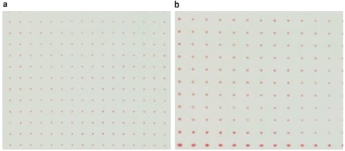
Fig. 4. Pressure distribution in a pressure-sensitive film rolled by a soft PDMS roller on a gas-pressurized platform and a rigid platform. The operating conditions are 0.4 kgf/cm2 of pneumatic pressure, 0.08 kgf/cm2 of gas pressure for the platform and 0.7 mm/s of moving speed. (a) Pressure distribution in the rolled film on gas-pressurized platform (b) pressure distribution in the rolled film on aluminum-PMMA platform.
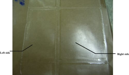
Fig. 5. A PET substrate with stamped polymeric microlens array.
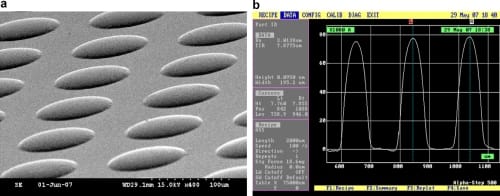
Fig. 6. SEM image of the fabricated resin microlens array and its surface profile. (a) SEM image of the resin microlens array (b) surface profile of the resin microlens array.
Based on the basic geometry and optical theory [12], the radius of curvature (R) and focal length (f) of the microlens can be calculated using the equations shown below:
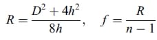
where D, h, and n are diameter, sag height of microlens, and the refractive index of the UV-curable resin, respectively. The calculated radius of curvature and the focal length of the present polymeric microlens are 215.6 &um;m and 428.8 &um;m, respectively. In order to characterize the uniformity of the formed microlens array, the surface profiles of randomly selected 20 microlenses from a single process are measured. The average diameter of microlens array is 115.11 &um;m with a standard deviation of 2.98 &um;m, and the average sag height is 7.94 &um;m with a standard deviation of 0.49 &um;m. In addition, the average radius of the curvature and the average focal length are 211.36 &um;m and 420.45 &um;m. These results indicate good uniformity of the rollingstamped microlenses.
3.3. Surface roughness and optical property of formed microlens array on PET
To characterize the surface topography of the fabricated ultraviolet-cured polymeric microlens, their surface roughness was measured with an atomic force microscope (AFM DI-3100, Digital Instruments, USA).
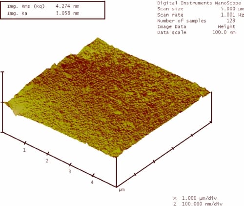
Fig. 7. AFM image and surface roughness measured in a 5 μm x 5 μm area on the top surface of the fabricated microlens. (The average surface roughness is 3.058 nm).
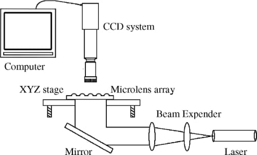
Fig. 8. Schematic of the setup for measuring the optical property of the polymeric microlens array.
Fig. 7 shows the surface roughness measured in a 5 μm x 5 μm area on the top surface of the fabricated microlens. The specimen is randomly selected from a single microlens array. The average surface roughness (Ra) is 3.058 nm, indicating a good optical smoothness on the microlens surface.
The optical property of the fabricated polymeric microlens array is further verified using a light focusing system. Fig. 8 shows the light focusing system which is composed of a microscope, a micrometer-scale-resolution Z-stage, a CCD camera system, a mirror, expanding lenses, and a 633 nm laser light source. The average focal length measured is 425 &um;m. The measured focal length agrees well with the calculated length. Fig. 9 shows a portion of the spot patterns produced by a UV-curable resin mic
rolens array in a monitor using a CCD camera. The images reveal that the pitch and the intensity of the focused light spots are uniform.

Fig. 9. The light spots pattern of a randomly selected area of formed microlens array.
4. Conclusions
This paper reports an innovative method for fabricating microlens array on flexible substrates using the soft roller stamping process. A novel design of soft roller stamping facilities with the capacity of UV exposure and gas-assisted pressurization has been constructed and tested. Under the proper processing conditions, a large array of polymeric microlens with a lens diameter of 115.5 μm, a pitch of 200 μm and a sag height of 7.88 μm has been successfully fabricated. The average surface roughness of the rollingstamped microlens is 3.058 nm. The pitch and intensity distribution of the fabricated micorlens array are uniform. These results show the great potential of the soft roller stamping process for continuous production of microlens arrays with high productivity and low-cost. This cost-effective technology can be further developed to a roll-to-roll process for fabrication of other components with microand nano-scale microstructures.
Acknowledgements
This work was partially supported by the Industrial Technology Research Institute of Taiwan (Under the grant of 6301XS7410). The authors wish to acknowledge the assistance, discussion, and encouragement from the co-workers at the Grace Laboratory for polymer processing in National Taiwan University.
References
- D. Daly, R.F. Stevens, M.C. Hutley, N. Davles, Meas. Sci. Technol. 1 (1990) 759–766.
- C.P. Lin, H. Yang, C.K. Chao, J. Micromech. Microeng. 13 (2003) 775–781.
- C.P. Lin, H. Yang, C.K. Chao, J. Micromech. Microeng. 13 (2003) 748–757.
- S. Mihailov, S. Lazare, Appl. Opt. 32 (1993) 6211–6218.
- K. Totsu, M. Esashi, J. Vac. Sci. Technol. B 23 (2005) 1487–1490.
- D.L. MacFarlane, V. Narayan, J.A. Tatum, W.R. Cox, T. Chen, D.J. Hayes, IEEE Photon. Technol. Lett. 6 (1994) 1112–1114.
- B.K. Lee, D.S. Kim, T.H. Kwon, Microsyst. Technol. 10 (2004) 531– 535.
- N.S. Ong, Y.H. Koh, Y.Q. Fu, Microelectron. Eng. 60 (2002) 365– 379.
- C.Y. Chang, S.Y. Yang, J.L. Sheh, Microsyst. Technol. 12 (2006) 754–759.
- C.Y. Chang, S.Y. Yang, M.H. Chu, J. Micromech. Microeng. 84 (2007) 355–361.
- C.Y. Chang, S.Y. Yang, L.S. Huang, J.H. Chang, Infrared Phys. Technol. 48 (2006) 163–173.
- S. Sinzinger, J. Jahns, Microoptics, Wiley–VCH, Weinheim, 1999, pp. 86–88.
