

Article
Related Links
*Pavan P. Jorwekar1, Yogesh V. Birari2, Mayur M. Nadgouda3 1Kirloskar Copeland Limited, Product Engineering Department,
Karad, Maharashtra, India
Phone +91 2164 241002 Fax +91 2164 241122 Email – [email protected]
2Kirloskar Copeland Limited, Product Engineering Department,
Karad, Maharashtra, India
Phone +91 2164 241002 Fax +91 2164 241122 Email – [email protected]
3Kirloskar Copeland Limited, Product Engineering Department,
Karad, Maharashtra, India
Phone +91 2164 241002 Fax +91 2164 241122 Email – [email protected]
*Indicates Corresponding Author
Abstract
As per the Montreal Protocol, the CFC refrigerants are being phased out and alternate refrigerants are being introduced for refrigeration system. In view of this the existing design schemes are required to be evaluated. The paper deals with evaluation of the contact pressure distribution of cylinder-head gasket to address the adverse pressure conditions
Pump assembly consists of reciprocating mechanism in which a cylinder head is fastened to crank case deck face with gasket in between them. The cylinder head essentially consists of suction and discharge plenums separated by walls and are subjected to respective pressures. With alternate refrigerant, the pressure difference across the suction and discharge plenum is increased. In order to address this increased pressure differential, the cylinder head gasket must have enough contact pressure across the discharge plenum and separating walls.
This paper elaborates the use of FEA tool – ANSYS, to analyze the cylinder head and gasket for gasket-joint. This analysis helped in finding the contact pressures across the gasket due to pre-torques applied through bolts. Design modifications were done for removing the low contact pressure zone areas on gasket. The gasket contact pressure pattern obtained in ANSYS was validated using Fuji film.
1. Introduction
Gasket joints are essential components in hermetic compressor. A gasket is a compressible material, or a combination of materials, which when clamped between two stationary members prevents the passage of the media across those members. The gasket material selected must be capable of sealing mating surfaces, resistant to the medium being sealed, and able to withstand the operating temperatures and pressures. In hermetic compressors gasket joints are most critical parts as sealing must be leak proof at all the operating conditions. Any damage to gasket sealing leads the entire compressor unusable. The rapid change from CFC refrigerant to non CFC and natural refrigerant put a very high demand on compressor manufacturers to develop new design for new environment friendly alternate refrigerants. For these alternate refrigerants, suction and discharge pressures are higher than conventional CFC refrigerants. So while designing the gasket joints one must consider the increased pressure across the suction and discharge plenum of the cylinder head.
In order to ensure the maintenance of the seal throughout the life expectancy of the assembly, sufficient pressure must remain on the gasket surface to prevent the damage to the gasket. A traditional way to find the contact pressure is by means of Fuji films. This activity requires lots of prototyping and testing. It is costly and time consuming as there is chance of re-looping when the expected results are not obtained. Here in this paper, explained the use of FEA tool for virtual method to find out the gasket pressure.
2. Problem Description
Gasket pressure depends on bolt tension and the amount of this bolt tension is transferred to the gasket is dependent on the stiffness of the cylinder head. Stiffer the cylinder head, more uniform distribution of bolt tension on the gasket. The objective of the analysis was to find out the distribution of cylinder head bolt tension on the gasket surface in terms of pressure for existing design.
3. Gasket Material
Gasket as sealing component between structural components are usually very thin and made of various materials, such as steel, rubber compounds and composites. From a mechanics point of view, gaskets act to transfer force between components. The primary deformation of a gasket is usually confined to one direction, i.e. through thickness. This behavior is most important sealing joint. In-plane stiffness (the stiffness contribution from membrane) and transverse shear is negligible when compared to the through thickness (ANSYS user guide). The stiffness contribution therefore is assumed to be negligible. Due to this, gasket behaves non-linearly in loading and unloading with permanent deformation. Typical gasket behavior is shown in Figure3 for synthetic material which is currently used in aforesaid Gasket. The loading and unloading curve was obtained from the following compression curve function of the gasket material.
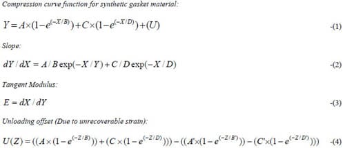
Equation 1 gives the compression of gasket for the particular value of stress X. U parameter in equation1 is unloading offset which is equal to zero for initial loading of the gasket. Equation 2 and equation 3 gives the slop and tangent modulus of the compression curve. Equation 4 gives the unloading offset of the gasket due to unrecoverable strain. Using equation 1 and equation 4, gasket compression and unloading behavior was calculated. Figure3 shows the gasket compression and unloading curve that were input to the ANSYS.
4. Problem Solving in ANSYS
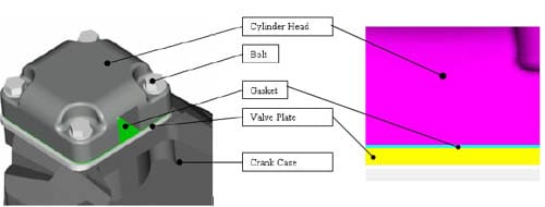
Figure 1: Cylinder Head and Gasket assembly
4.1 Model Simplification and assumption
CAD models of cylinder head, gasket, valve plate and crank case was created in I-DEAS NX2. These models were geometrically simplified for ease of meshing. Only the crank case deck has considered for the analysis as there is negligible effect of bolt torque on remaining part of the crank case. This has reduced the model size and solution time.
The following are the assumptions:
- Bolt torque sequencing is ignored and torque applied simultaneously
- Gasket and cylinder head material assumed to be h
omogenous. - Valve plate and crank-case assumed to be single part.
- Effect of operating temperature on gasket behavior is not considered in the analysis.
4.2 Pre-processing
ANSYS offers a series of elements to model gaskets. These elements belong to the ANSYS family of interface elements. For these elements, the membrane and transverse shear are neglected for gasket simulations. A gasket material option has been designed especially to account for the gasket through thickness behavior. This option should be used in a microscopic investigation of how gasket joints behave and does not predict the response of the gasket, but rather allows the user to input the response of the material. In this analysis, gasket material behavior was obtained form compression curve equation. One may focus on the behavior of the joint rather than detailed study of the gasket. If the detailed gasket results are desired, more sophisticated material models will be required.
For this problem INTER194 is selected to model the gasket. INTER194 is a 3-D 16-node quadratic element. It is defined by 16 nodes having three degrees of freedom at each node: translations in the nodal x, y, and z directions. Cylinder head and crank-case is meshed using Solid 92 elements. Bolt toque is converted into axial force and applied on the cylinder as shown in Figure2. Base of crank-case part is constrained in all degrees of freedoms. Material properties for cylinder head and valve plate such as modulus of elasticity, poisons ratio were defined.
The gasket material compression and unloading data were input to the ANSYS. The GASKET option in ANSYS allows directly input data for complex pressure closure curves. The GASKET option also offers two sub-options to define gasket unloading behavior including linear and nonlinear unloading. The linear unloading option simplifies the input by defining the starting closure at the compression curves and the slope. The nonlinear option allows to directly input unloading curves to more accurately model the gasket unloading behavior. In this simulation nonlinear option was used for both compression and unloading condition to simulate accurate behavior of the gasket.
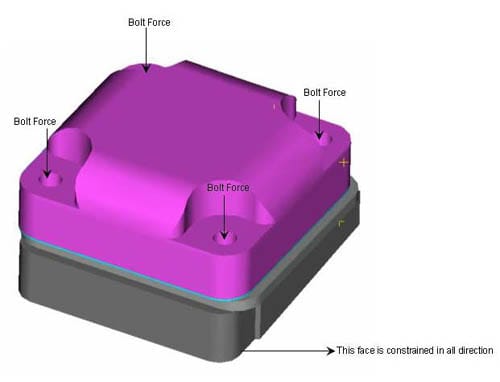
Figure 2: Boundary condition
5. Experimental Validation
The Fuji pre-scale pre-stressing sensitive films works like litmus paper. It consists of thin polyester film that contains a layer of tiny microcapsules. The application of force upon the film causes the microcapsules to rupture, producing as instantaneous and permanent high resolution of pressure variation across the contact area. The color intensity of the image created is directly related to the amount of the pressure applied. The greater pressure shows more intense color. For experimental analysis, Fuji film was inserted between valve plate and cylinder head. This assembly was then bolted to the crank and specified bolt torque was applied. Figure5 shows the result obtained form Fuji film test.
6. Results and Discussion
Figure6 shows the result obtained from FEA method. The FEA results are in well agreement with the Fuji film test. The areas encircled in Figure5 and Figure6 is where the gasket pressure is low. Using the results obtained from the analysis and validation from Fuji film test, cylinder head was modified accordingly to ensure the gasket pressure is enough to withstand the differential pressure across the suction and discharge plenum. The new designed cylinder head was tested for the maximum pressure differential that can occur during operating condition.
By analyzing the sealing performance, it is possible to improve the sealing joints. In future design, Fuji film test can be done only with finalized design. This will reduce the cost, development time and improve reliability of the compressor.
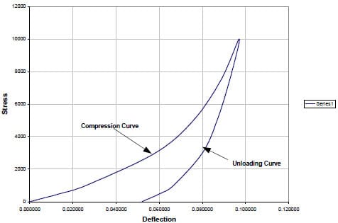
Figure 3: Stress vs. Deflection Responses for the Gasket Material
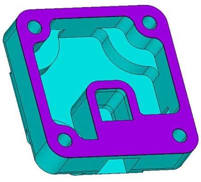
Figure 4: FEA model of Cylinder Head and Gasket
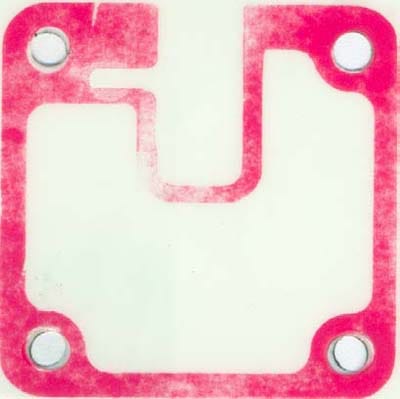
Figure 5: Gasket contact pressure obtained from Fuji film test.
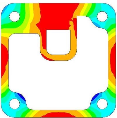
Figure 6: Gasket pressure pattern obtained from ANSYS
NOMENCLATURE
Y = Strain or % Compression
X = Stress
A, C = Scale Factors
B, D = Time Constants
U = Unloading Offset (U=0 for loading curve)
Z = maximum stress achieved
References
- ANSYS 8.1, User Manual, Raub Jonathan,1999 Modeling Diesel Engine Cylinder Head Gaskets using the Gasket Material Option of the SOLID185 Element
MSC Worldwide Automotive Conference
Fuji Corporations “ Fuji Prescale film operating instructions”.
![]()