


Venus flytrap biomechanics: Forces in the Dionaea muscipula trap

Alexander G. Volkova, Shawn L. Harris IIa, Chrystelle L. Vilfranca, Veronica A. Murphya, Joseph D. Wootena, Henoc Paulicina, Maia I. Volkovaa, and Vladislav S. Markinb
aDepartment of Chemistry and Biochemistry, Oakwood University, Huntsville, AL 35896, USA
bDepartment of Neurology, University of Texas, Southwestern Medical Center, Dallas, TX 75390-8813, USA
Keywords: Carnivorous plant, Electrophysiology, Morphing structures, Plant biomechanics, Venus flytrap
Abstract
Biomechanics of morphing structures in the Venus flytrap has attracted the attention of scientists during the last 140 years. The trap closes in a tenth of a second if a prey touches a trigger hair twice. The driving force of the closing process is most likely due to the elastic curvature energy stored and locked in the leaves, which is caused by a pressure differential between the upper and lower layers of the leaf. The trap strikes, holds and compresses the prey. We have developed new methods for measuring all these forces involved in the hunting cycle. We made precise calibration of the piezoelectric sensor and performed direct measurements of the average impact force of the trap closing using a high speed video camera for the determination of time constants. The new equation for the average impact force was derived. The impact average force between rims of two lobes in the Venus flytrap was found equal to 149 mN and the corresponding pressure between the rims was about 41 kPa. Direct measurements of the constriction force in the trap of Dionaea muscipula was performed during gelatin digestion. This force increases in the process of digestion from zero to 450 mN with maximal constriction pressure created by the lobes reaching to 9 kPa. The insects and different small prey have little chance to escape after the snap of the trap. The prey would need to overpower the escaping force which is very strong and can reach up to 4 N.
Introduction
Many plants have the ability to alter their physical characteristics and become shape-changers with a low turning radius, long endurance, and high speed (Markin et al., 2008; Markin and Volkov, 2012). The rapid closure of the Venus flytrap upper leaf in about 0.1 s is one of the fastest movements in the plant kingdom (Darwin, 1875, 1880). The Venus flytrap is an American plant that lives in warm swamp areas in North and South Carolina. According to Darwin (1875, 1880), the Venus flytrap, from the rapidity and force of its movements, is one of the most wonderful plants. The hydroe- lastic curvature mechanism (Markin et al., 2008) closely describes the kinetics of the Venus flytrap leaf movements. The driving force of the closing process is most likely a result of the elastic curvature energy stored and locked in the leaves due to a pressure difference between the upper and lower layers of the leaf (Markin et al., 2008). The open state of the trap contains high elastic energy accumulated by the hydrostatic pressure difference between the hydraulic layers of the lobe. The trigger signal opens the water pores between these layers and the fluid transfers from the upper to the lower layer. The leaf relaxes to its equilibrium state, corresponding to the closed configuration. This process develops very quickly, a fraction of a second. Markin et al. (2008) derived equations describing this system based on elasticity Hamiltonian and found kinetics of the closing process.
It is important to understand the mechanics of the trap closure. The leaves of the Venus flytrap plant can be compared to an open book with a fly sitting on the page; the fly can be caught by immediate shutting the book. However, this comparison would be a very basic representation of the mechanics attributed by the Venus flytrap. In the book model, there is a pivot at the midrib of the leaf and two sides of the book would rotate around this pivot and crush the fly. The closing of the Venus flytrap occurs differently due to the fact that the midrib is not a pivot.
The accumulated data suggest that elastic energy does play an important role, but driving force behind this event involves another process that determines the transformation from an open to a closed state. The Hydroelastic Curvature Model includes a system of bending elasticity, turgor pressure, and water jets. The closure of the Venus flytrap represents the non-muscular movement based on hydraulics and mechanical elasticity. The nastic movements demonstrated in various plants involve a large internal pressure (turgor) actively regulated by plants.
In the Hydroelastic Curvature Model the leaf of the Venus flytrap is visualized as a thin, weakly-curved elastic shell with principal natural curvatures that depend on the hydrostatic state of the two surface layers of cell A and B, where different hydrostatic pressures PA and PB are maintained.
Two layers of cells, mechanically connected to each other, behave like a very popular idea in membrane mechanics, regarding bilayer couple, where the in-plane expansion or contraction of any of them causes the change of curvature of the whole leaf. The two halves of the membrane bilayer may respond differently to various perturbations while remaining coupled to one another. One half of the bilayer may expand in the plane of the membrane relative to the other half of the bilayer, while the two layers remain in contact with one another. This leads to various functional consequences, including shape changes of the intact cell. This concept is called the bilayer couple hypothesis because of the analogy of the response of a bimetallic couple to changes in temperature. This concept has remained very popular and commonly applied to the explanation of numerous phenomena, such as red blood cell transformations and the gating of mechanosensitive channels.
In the Venus flytraps open state, the pressure in the upper layer is higher than in the lower layer, maintaining the convex shape of the leaf. The fact, that the hydrostatic pressure in different parts of the plant can vary, is very well known. This knowledge further exemplifies (Tamiya et al., 1988) that stimulation of a Mimosa plant causes very fast redistribution of water. Tamiya et al. (1988) found that after stimulation, water in the lower half of the main pulvinus is transferred to the upper half of the main pulvinus. Movement of the water in conjunction with Mimosa movement was visualized by a non-invasive NMR imaging procedure (Detmers et al., 2006). This fast water redistribution is obviously compelled by the pressure difference between different parts of the plant. Exchange then occurs through open pores. Unfortunately, the anatomy and the nature of these pores are not currently known. Therefore, for the mechanical analysis, their existence was simply accepted.
At the resting state of the Venus flytrap plant, water pores between the two hydraulic layers are closed. The external trigger, either mechanical or electrical, sparks the opening of these connecting pores. Water rushes from the upper layer to the lower layer. The bilayer couple quickly changes its curvature from convex to concave and the trap closes.
The Venus flytrap can be closed by mechanical stimulation of trigger hairs using a cotton thread or wooden stick to gently touch one or two of the six trigger hairs inside the upper leaf of the Venus flytrap. The cotton thread was removed before the leaves closed. The closure of the leaves could also be stimulated by small pieces of gelatin. The Venus flytrap could also be closed by an electrical pulse between the midrib and a lobe of the upper leaf without mechanical stimulation (Markin and Volkov, 2012; Volkov et al., 2007, 2008a, 2009b, 2011). The closing was achieved through the electrical stimulation with a positive electrode connected to the midrib and a negative electrode placed in one of the lobes. It should be noted that inverted polarity pulse was not able to close the plant, and the closed trap could not be opened by electrical stimulus lasting up to 100 s.
A single electrical pulse exceeding a threshold of 1.5 V causes closure of a trap and induces an electrical signal propagating between the lobes and the midrib. When charges were smaller, the trap did not close. Repeated application of small charges demonstrates a summation of stimuli. Two or more injections of electrical charges within a period of less then 50 s closed the trap as soon as a total of 14 µC charge is applied. Traps closing by electrical stimulus obey the all-or-none law which states: there is no reaction for stimulus under the threshold and the speed of closing does not depend on stimulus strength above the threshold (Volkov et al., 2008b, 2009a,b).
Closing the upper leaf consists of three distinctive phases (Volkov et al., 2011). Immediately after stimulation, there is a mechanically silent period with no observable movement of the plant. The first mechanically silent stage of the trap closing involves transduction of electrical signals and hence it is related to ion chan- nel gating. It is sensitive to agents interfering with ion channels. For more details see Volkov et al. (2008b). This is followed by a period when the lobes begin to accelerate. The third period of fast movement is what is witnessed as the actual trapping behavior, when the leaves quickly relax to the new equilibrium state.
The trap closing stage does not exhaust the whole process of catching and digesting insects by the Venus flytrap. After closing, the trap should be locked when cilia, finger-like protrusions, bend around the edges and tighten the gap. We regard this third phase as the locked state. After reaching the locked state, the lobes flatten, the trap depresses the prey and the digestion process begins. The trap starts to open after 57 days of digestion and after a day it will be opened with the lobes in concave shape. Though the trap will be completely open, another day is required for changing of the trap from a concave to a convex shape. The trap will then be completely opened. Therefore, the total hunting cycle of the Venus flytrap consists of five stages: 1. Open state --> 2. Closed state --> 3. Locked state --> 4. Constriction and digestion --> 5. Semi-open state --> 1. Open state.
Our results enable us to explore new types of highly efficient natural osmotic motors and electrically controlled morphing structures with optimum performance (Markin et al., 2008; Volkov et al., 2007, 2008a,b, 2009a,b, 2011, 2012).
Each lobe of the Venus flytrap has 3 or 4 mechanosensitive trigger hairs. Touching trigger hairs protruding from the upper epidermal layer of the Venus flytraps leaves activates mechanosensitive ion channels. As a result, receptor potentials are generated which in turn induce a propagating action potential throughout the upper leaf of the Venus flytrap (Benolken and Jacobson, 1970; Burdon-Sanderson and Page, 1876; Jacobson, 1965; Volkov et al., 2007, 2008a). A receptor potential always precedes an action potential and couples the mechanical stimulation step to the action potential step of the preying sequence (Jacobson, 1965). A possible pathway of action potential propagation to the midrib includes vascular bundles and plasmodesmata in the upper leaf (Buchen et al., 1983; Ksenzhek and Volkov, 1998; Volkov, 2006, 2012a,b). Trap closure and prey retention in the Venus flytrap temporarily reduces photosynthesis and stimulates respiration (Pavlovic et al., 2010, 2011).
Upon closure, the cilia protruding from the edge of each lobe form an interlocking wall that is impenetrable to all except the smallest prey (Juniper et al., 1998; Lloyd, 1942). The trap uses the double-trigger mechanism and shuts when the prey touches its trigger hairs twice in succession within a 30 s window of time. Partial closure allows the cilia to overlap, however, the lobes are still held slightly ajar. This partial closure occurs in a fraction of a second, and several minutes may be required for the lobes to come together fully. When a prey is caught, the lobes seal tightly and thus remain shut for 57 days, allowing digestion to take place (Jaffe, 1973; Volkov et al., 2011). The stalk and basal cells containing lipid globules and the common wall between these two cells are traversed by numerous plasmodesmata (Williams and Mozingo, 1971). Electron micrographs of the trigger hairs reveal three regions where the cells differ in size, shape, and cytoplasmic content. The basal walls of the indentation cells contain many plasmodesmata. Plasmodesmata found in anticlinal and podium cells pass through constricted zones in the cell wall. There are numerous plasmodesmata in the peripheral podium cells (Mozingo et al., 1970). The lobes of the Venus flytrap move because of changes in shape, curvature, and volume of cells.
Literature on plant biomechanics traditionally covers such topics as cell walls and plant growth, tissue mechanical properties, mechanoperception and posture control, hydraulics and wood anatomy, ecology, tree biomechanics, and membrane biomechanics (Hamant and Traas, 2010; Niklas et al., 2006; Shahinpoor, 2011; Schopfer, 2006; Volkov et al., 1998). Some of these phenomena are interconnected with electrical properties of plant tissue and depend on biologically closed electrical circuits in plants. We found that electrochemical circuits in the Venus flytrap and Mimosa pudica can regulate their biomechanics (Markin et al., 2008; Volkov et al., 2009b). We estimated electrical charge, current, resistance, electrical energy and electrical power dependencies on time during electrostimulation of the trap using the Hydroelastic Curvature Model and compared with experimental data velocity, acceleration and kinetic energy from the time dependencies of distance between rims of lobes during the trap closing.
Recently, we presented our results for estimation of the closing force of the trap of the Venus flytrap after mechanical or electrical stimulation of the trap using the piezoelectric thin film (Volkov et al., 2012). Now we developed new equation for the average impact force and using high speed video camera for the determination of time constants we are able to make more precise calibration of the piezoelectric sensor and direct measurements of the average impact force of the trap closing.
The goal of this study is the measuring of mechanical forces in the Venus flytrap responsible for the trap closing and constriction during digestion. We have developed new methods for mechanical forces and pressure measurements in the Venus flytrap.
Materials and methods
Plants
The Dionaea muscipula Ellis (Venus flytrap) were purchased from Fly-Trap Farm Supply (North Carolina, USA) and grown in well drained peat moss in plastic pots at 22 °C with 12:12 h light: dark photoperiod. The humidity averaged 4550%. Irradiance was 700800 µmol photons m-2 s-1. The soil was treated with distilled water. All experiments were performed on healthy adult specimens from the one hundred bulbs purchased.
Trap closing average impact force measurement: piezoelectric sensor
It is important to measure the average impact force in carnivorous plants. In the process of closing, the lobes of the Venus flytrap move very quickly and rims of the lobes hit each other with a certain force. Our goal is to measure this force. It can be achieved with help of piezoelectric sensor which can measure the force of this strike between rims. The piezoelectric force measurement is based on the piezoelectric effect. Piezoelectric measuring systems are active electrical systems, which produce an electrical output only when they experience a change in load. They offer excellent quasistatic measuring capability, but they cannot perform true static measurements. A very high input impedance data acquisition board NI-PXI-6115 can record their voltage Fig. 1b), which is proportional to mechanical loading.
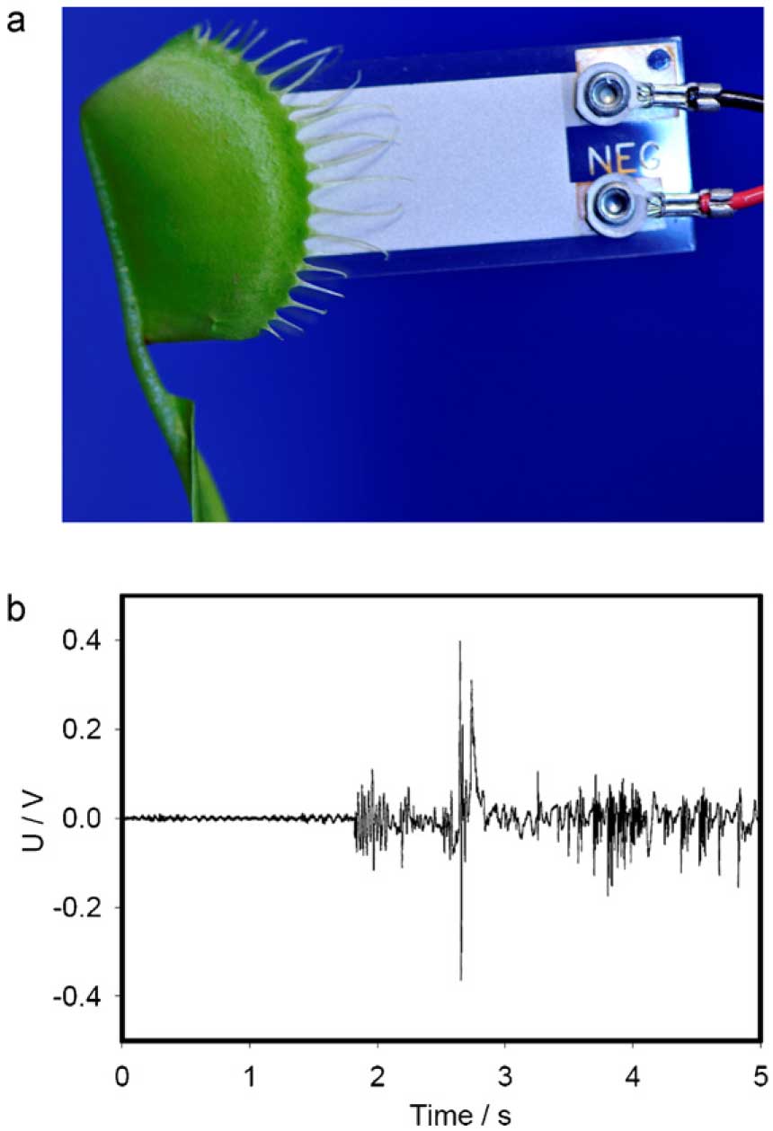
Fig. 1. (a) Insertion of the piezoelectric film PZ-03 into trap; (b) electrical response of the piezoelectric film PZ-03 on the trap closing and locking.
We used PXI (PCI eXtensions for Instrumentation), a rugged PC-based platform, as a high-performance measurement and automation system (Jovanov and Volkov, 2012). High speed data acquisition of low-pass filtered signals was performed using microcomputers with simultaneous multifunction I/O plug-in data acquisition board NI-PXI-6115 (National Instruments, Dallas, TX, USA) interfaced through a NI SCB-68 shielded connector block to a piezoelectric sensor. The system integrates standard low-pass anti-aliasing filters at one half of the sampling frequency (Jovanov and Volkov, 2012). The multifunction data acquisition board NIPXI- 6115 provides high resolution and a wide gain range. Any single channel can be sampled at any gain at 10 million samples/ s. The sensor film was inserted between two lobes above the midrib (Fig. 1a). The average impact force of the trap closing was measured by the piezoelectric sensor PZ-03 (Images Scientific Instruments, Staten Island, New York). Piezoelectric film has a thin urethane coating over the active sensor area. The size of film was 6 mm × 41 mm × 0.2 mm. For the calibration of the dependence of the sensor electrical response on the applied force, laboratory standard weights (Fisher Scientific, USA), were dropped on the piezoelectric sensor film from 7 cm above PZ-03. Digital high speed video camera system Olympus i-Speed 3 was used to measure the height of standard weights traveled after impact and duration of contact between the moments of the impact and bounce.
For calibration of the piezoelectric sensor electrical response, we dropped different weights on the piezoelectric sensor film from 7 cm above PZ-03. Average impact force was estimated from the following equation for elastic impact.
In the following derivation we defined direction up as positive and direction down as negative. Let h1 be the height from which a weight was dropped, h2 is the height of bounce after impact. Then velocities at the beginning v1 and at the end v2 of contact are equal to

According to the Newtons second law, the net force is the rate of change of its linear momentum p = mv in inertial reference frame. For the falling weight of mass m, we can write for the elastic impact:

or

where g is the acceleration due to gravity, T is a duration of contact between the moments of the impact and bounce.
Average acceleration is equal to

and the average impact force for the elastic impact is equal to

High speed video recording was used to measure h2 and T. The electrical signal was measured using a NI PXI-6115 DAQ. In our previous work we used another independent method for force and pressure measurement: ultra low Fuji Prescale© film (Sensor Products Inc., Madison, NJ). We found that this film changes color proportional to applied pressure, but it can also change color even without applied pressure if pH decreases. As a result of pH dependence, ultra low Fuji Prescale film should not be used in the trap during gelatin digestion.
Force of the trap constriction measurements
After the trap closing and locking, there is an additional constriction force between the lobes in the presence of a captured prey. We used gelatin as an artificial prey which is a source of amino acids for the Venus flytrap during digestion. The gelatin filled sponge (Dry Fast Foam Upholstery Décor, Inc., USA) with cross surface area of 0.5 cm2 was used to evaluate the force developed by the Venus flytrap during the constriction phase (Fig. 2). A calibration curve representing the sponge thickness as a function of applied force was measured (Fig. 3). Cylinder laboratory standard weights were placed on the sponge. Each sponge surface was smaller than the surface of the cylinder standard weights ensuring that the force of the weights was equally distributed on the sponge so that the calibration curve would be accurate. The weights used for calibration ranged from 5 to 100 g. Once the weights were placed on the sponge, the height of the foam was measured using a Digital Caliper. After calibration, the foam was immersed again in the 4% gelatin from porcine skin (Fluka, New York, NY, USA). After 10 min, the sponge was placed between lobes of the Venus flytrap (Fig. 2b). Measurements of the distance between the centers of the Venus flytraps lobes (Fig. 2c) were taken by using the Digital Caliper. Distances between the lobes, with a gelatin filled sponge in the trap, were measured until it reaches full compression. The thickness of the trap lobes was practically constant during the trap constriction.

Fig. 2. Experimental setup for the measurements of the trap constriction force: (a) a sponge; (b) closed trap with a foam and gelatin; (c) the closed trap of the Venus flytrap. The arrows denote the distance between the middle of lobes.

Fig. 3. Calibrating curve for the sponge saturated by gelatin.
Pressure of the trap constriction measurements: Pressurex-micro© film
We are going to measure not only a force, but also pressure of the trap constriction. Constriction pressure can be found from previous experiment by dividing the force by the surface of the sponge. We also used another independent method with help of the ultra low Pressurex-micro© film (Sensor Products Inc., Madison, NJ, USA) for evaluating the distribution and magnitude of pressure between the middle of the lobes of the Venus flytrap during trap compression and digesting. A protective cover of plastic Mylar film was placed on both sides of the Pressurex-micro© film prior to the addition of the gelatin. A small piece of 4% gelatin was placed on both sides of the film. Ultra low Pressurex-micro© film with dimensions of 0.5 cm × 0.5 cm was inserted between the lobes and slanted toward the lobe to cause stimulation of the trigger hairs. It is important to note that the all sensing film was placed inside the trap (Fig. 4). Ultra low Pressurex-micro© film consists of three distinct layers. The middle layer, or carbon layer, is a combination of thick white paper and black carbon. The bottom layer, or adhesive layer, consists of three layers within itself a protective release liner covering an adhesive coated white paper backed by a thick white stock.

Fig. 4. Insertion of ultra low Pressurex-micro© film into the trap and calibration of ultra low Pressurex-micro© film.
To convert the results of measuring the deformation of Pressurex-micro© film to pressure we need to calibrate this device. After cutting the film into 2 cm by 2 cm pieces, the carbon layer was placed on the adhesive layer. No pressure is allowed to be placed on the film except by the weights used for calibration. Fisherbrand Microscope Cover Glasses (Fisher Scientific, USA) were placed on the top and bottom of each Ultra low Pressurex-micro assembled film. The film and cover glasses were placed on medium circular tubes. The tubes and cover glasses were used as stands so that an equal distribution of pressure was placed on the film by the weights. Calibration began by placing a weight on the film for 5 min. The films were examined by carefully stripping the adhesive layer from the carbon layer. No pressure was allowed to be placed on the film during this time. The adhesive layer was then examined further by taking digital pictures (Fig. 4). This calibration of the Pressurexmicro © film is a very rough method and can give approximately value of pressure between lobes in the Venus flytrap if we compare experimental results and calibration images in Fig. 4.
Escaping force measurements
If a prey or part of a prey is captured by the Venus flytrap, usually it cannot escape the trap (Lloyd, 1942). To escape the trap, the prey must be able to apply a significant force. We used two methods to measure the preys escaping force with help of the artificial prey model made from Teflon©. We shall place this artificial prey into the trap, cause it to close and then pull it out measuring the force. The plants were placed inside a Faraday cage (Fig. 5) on the top of a stainless steel laboratory scissor jack (ScienceLab.com, Inc., Houston, TX, USA). Foam padding was provided to eliminate the presence of vibration in our experiments. New Venus flytraps were used for each experiment. A 2 cm Teflon© tube with a diameter of 4 mm was cut along the vertical length, creating a single half section which was fashioned to replicate the curved shape of the lobes. The middle of this piece was then punctured to allow a 19 cm Eagle Claw Nylon fishing string to be tied through its center. Using this small metal fishing hook on the other end of the nylon string, an artificial prey was created allowing the Teflon© tubing to be placed into the trap. This also assisted in the upward suspension of the lobes around the tube which would later provide readings of force. The tubing was coated with gelatin prior to being placed inside the trap to simulate the Venus flytraps natural digestive behavior upon closing. The Mettler Toledo AG balance model AG 104 (Mettler Toledo, Switzerland) was placed on top of the Faraday cage, positioned above the plant. The Nylon fishing string was hooked to the bottom of the balance. The opposite end of the string, containing the Teflon© tube, would later be placed inside the trap (Fig. 5). The Mettler Toledo balance was interfaced through a LocalCan RS232 DB9 MF cable to a computer with Balance Link v 3.0 Mettler Toledo software. The escaping force was measured by the Mettler Toledo balance when the plant was pulled downward by the metal jack until the opening the trap and escaping of the artificial prey model made from Teflon©.

Fig. 5. Experimental setup for the prey escaping force measurements.
The Dual-Range Force Sensor (Vernier, Beaverton, OR, USA), a general-purpose sensor for measuring the pushing and pulling forces, was used as a second independent method for measuring the escaping force. The provided ranges allow the measurement of forces as small as 0.01 newtons and as large as 50 N. The Force Sensor was interfaced to a computer using Vernier Lab Pro data acquisition system. Results were recorded using Logger Pro software (Vernier, Beaverton, OR, USA). The Dual-Range Force Sensor uses strain gage technology to measure force, based on the bending of a beam. Strain gages attached to both sides of the beam change resistance as the beam bends. The strain gages are used in a bridge circuit such that a small change in resistance will result in a change in voltage. This voltage change is proportional to the change in force.
Images
Digital high speed video camera system Olympus i-Speed 3 (Houston, TX, USA) was used to collect digital images, which were analyzed frame by frame. Olympus i-Speed 3 video camera system has maximum sampling frequency of 150,000 frames per second. A photo camera Nikon D3x with AF-S Micro Nikkor 105 mm 1:2.8 G ED VR lens (Nikon, Melville, NY, USA) was used for the photography of the Venus flytrap.
Results
Eq. (5) for elastic impact can give the estimate of the average impact force between the rims immediately after the trap closing from above: the actual force can be somewhat smaller. In our experiments the mass of the falling weight was 0.2 g, the height from which a weight was dropped was h1 = 7 cm, the height traveled after the impact was h2 = 0.5 cm, and a duration of contact between the moments of the impact and bounce was T = 2 ms. High speed video recording was used to measure h2 and T. The electrical signal was measured using a NI PXI-6115 DAQ. The average trap closing force was found to be about 0.149 N according to Eq. (5).
Fig. 6 shows variation of distance between the middle of lobes (Fig. 1c) with time in the presence of a sponge with gelatin in the trap. Experimental results obtained in twenty different traps on twenty different plants are very similar. During gelatin digestion by the Venus flytrap, the distance between lobes decreases because of compressing force increasing. Using the calibration dependence of force on thickness of a sponge shown in Fig. 3, it is possible to the measured distance into force during the gelatin digestion by the Venus flytrap (Fig. 7) using data from Figs. 3 and 6.

Fig. 6. Time dependencies of the distance between the middle of the lobes of the Venus flytrap during digestion of gelatin. The sponge with gelatin was placed in the trap as shown in Fig. 2b and distance was measured as is shown in Fig. 2c.

Fig. 7. Dependence of the trap constriction force on time. The sponge with gelatin was placed in the trap as shown in Fig. 3b and Fig. 2b and distance was measured as is shown in Fig. 2c. Solid line is theoretical according to Eq. (6).
The constriction force in the trap during gelatin digestion gradually increases from zero to 0.45 N (Fig. 7), which corresponds to the constriction pressure of 9 kPa.
From curve fitting we found that time dependence of the constriction force (Fig. 7) can be approximated by two-exponential equation:

where t is time, a = 54.1761 N, b = 1.0545 s-1, c = 557.6594 N, d = 0.0156 s-1.
Fig. 8 shows that the constriction force in the trap during gelatin digestion is proportional to the distance Δx between centers of lobes according to Hookes equation with k = 141 N/m.

Fig. 8. Dependence of the trap constriction force on distance between centers of lobes of the Venus flytrap. The sponge with gelatin was placed in the trap as shown in Fig. 2b and distance was measured as is shown in Fig. 2c.
By placing the ultra low Pressurex-micro© film and gelatin between the lobes of the Venus flytrap, we determined the constriction pressure between the centers of the lobes during the gelatin digesting. Once the digestion and the trap compression were complete, and the Venus flytrap had fully opened, the film was removed without adding any additional force to the film. The carbon layer was then discarded. Fig. 9 shows the image of ultra low Pressurex-micro© film after opening of the trap. The maximal pressure between the centers of the lobes during a gelatin digestion was between 5 and 10 kPa. This ultra low Pressurex-micro© film can give only rough estimate of pressure. Fig. 4 shows the calibration of a film by applying different forces.
Fig. 5 demonstrates the set up for which the escaping force was measured. To measure this force, the plant, which was placed on the scissor jack as shown in Fig. 5, was lowered away from the balance. The jack was lowered slowly until the gelatin coated Teflon© tube was fully released from the plant. As in nature, the plant resisted the Teflon© preys escape. The Teflon© prey is able to acquire great escaping force since it is connected to the string attached under the balance.
Fig. 10 shows the escaping force from the trap of a Teflon© prey, which was measured directly as shown in Fig. 5. We lowered the plant until the prey escaped. In Fig. 10, each dot represents a separate experiment using a different trap each time. These experiments in Fig. 10 measure force over a 24 h period with a maximum force of 4 N. This force is caused by four forces: the rims closing force, the cilia locking force, the constriction force, and a friction between a Teflon© prey and lobes. It is well known that insects and different small preys cannot escape after very fast trap closing and now we know from our force measurements that the escaping force is very strong and can reach 4 N (Fig. 10). From curve fitting we found that time dependence of the escaping force (Fig. 10) can be approximated by the exponential equation:

where y0 = 188 mN, a = 3.713 N and b = 0.078 min-1. From this equation, we can conclude that the value 188 mN represents the initial force utilized by the trap to hold the prey upon closure. This holding force has a gradual increase with time, of up to y0 + a = 3.9 N with characteristic time 1/b = 12.8 min.

Fig. 10. Dependence of the escaping force from the closed trap on time. Experimental setup is shown in Fig. 6.
Discussion
The Venus flytrap captures insects with one of the most rapid movements in the plant kingdom. Plants can perceive mechanical stimuli. This process involves mechanosensitive channels that are found in all types of cells, from animal and plant cells to fungi and bacteria. These channels are ideal transducers of physiologically relevant mechanical forces and are involved in the growth, development, and response to environmental stress in higher plants. Mechanosensitive ion channels in plants are activated by mechanical stress and then this information can be transduced into electrical signals. Perception and response to mechanical stimuli are essential at the cellular and organismal levels. Touching trigger hairs, protruding from the upper leaf epidermis of the Venus flytrap, activates mechanosensitive ion channels and generates receptor potentials, which can induce action potentials. Venus flytrap can be closed by a mechanical or electrical stimulation of trigger hairs.
When the Venus flytrap catches the insect it does not crush the prey but rather hugs it by building the cage around it. This is achieved by bending the lobes. The curvature of the lobes changes during closing of the trap from convex to concave configuration. The trap changes from a convex to a concave shape in about 100 ms. There is a very small tightening of lobes during the first five minutes. Cilia on the rims of the lobes bend over and lock the edges (Fig. 2c). The trap can stay in such a position for a few hours before opening if the prey is too small for digesting.
Upon closure, the cilia protruding from the edge of each lobe form an interlocking wall that is impenetrable to all except the smallest prey. The trap uses the double-trigger mechanism and shuts when the prey touches its trigger hairs twice in succession within a 25-s window of time. Partial closure allows the cilia to overlap, however the lobes are still held slightly ajar. This partial closure occurs in a fraction of a second, and several minutes may be required for the lobes to come together fully. When a prey is caught, the lobes seal tightly and thus remain for 57 days, allowing digestion to take place.
Since the area of lobes contact during the trap closing was 3.64 × 10⁻⁶m2 (Volkov et al., 2012), we can estimate approximate pressure by dividing force by the area of contact, which is equal to 0.149 N/0.00000364 m2 = 40.9 kPa.
We found that the trap closing force is 0.149 N and pressure between rims of the lobes is 40.9 kPa. Due to this reason, when the Venus flytrap catches large enough insects, they cannot move outside the trap due to high pressure between the rims, but entrapped insect can move inside the trap and trigger additional action potentials by trigger hair irritation for hours (Affolter and Olivo, 1975; Volkov et al., 2011, 2012). For digesting the prey, the Venus flytrap needs to compress lobes and decrease volume inside the trap and distance between the lobes. This process we call the constriction of the trap. We used gelatin as a prey model. Fig. 9 shows the image on Ultra Low Pressurex-micro© film which approximately corresponds to the constriction pressure of 510 kPa. Forces of constriction can rich 0.45 N (Figs. 7 and 8). Since the cross surface area of a gelatin filled sponge was 0.5 cm2, we can estimate the constriction pressure which is equal to 0.45 N/0.00005 m2 = 9 kPa. Both methods of pressure measurements give us approximately the same value of the constriction pressure. The pressure between the rims of the lobes is 4.5 times higher than the constriction pressure between lobes. According to Eq. (7), the initial holding prey force is equal to 0.188 N immediately after the trap is closed. This force is slightly higher than the traps closing force of 0.149 N. During the gelatin digestion, the escaping force increases to 3.9 N.

Fig. 9. Image of ultra low Pressurex-micro© film after opening of the trap.
Strong tightening of the rims is important for the Venus flytrap to keep a prey inside the trap and to avoid leaking from the trap during the prey digestion.
Acknowledgments
This article is based upon work supported in part by the National Science Foundation under grant no. CBET-1064160 and in part by the U.S. Army Research Office under contract/grant number W911NF-11-1-0132.
References
- Affolter JM, Olivo RF. Action potentials in Venuss-flytraps: Long-term observations following the capture of prey. Am Midland Nat 1975;93:4435.
- Benolken RM, Jacobson SL. Response properties of a sensory hair excised from Venuss flytrap. J Gen Physiol 1970;56:6482.
- Buchen B, Hensel D, Sievers A. Polarity in mechanoreceptor cells of trigger hairs of Dionaea muscipula. Planta 1983;158:45868.
- Burdon-Sanderson J, Page FJM. On the mechanical effects and on the electrical disturbance consequent on excitation of the leaf of Dionaea muscipula. Philos Proc R Soc London 1876;25:41134.
- Darwin C. Insectivorous plants. London: Murray; 1875.
- Darwin C. The power of movement in plants. London: Murray; 1880.
- Detmers FJM, De Groot BL, Mueller EM, Hinton A, Konings IBM, Sze M, et al. Quarternary ammonium compounds as water channel blockers: specificity, potency, and site of action. J Biol Chem 2006;281:1420714.
- Hamant O, Traas J. The mechanics behind plant development. New Phytol 2010;185:36985.
- Jacobson SL. Receptor response in Venuss flytrap. J Gen Physiol 1965;49:11729.
- Jaffe MJ. The role of ATP in mechanically stimulated rapid closure of the Venuss flytrap. Plant Physiol 1973;51:178.
- Jovanov E, Volkov AG. Plant electrostimulation and data acquisition. In: Volkov AG, editor. Plant electrophysiology. Methods and cell electrophysiology. Berlin: Springer; 2012. p. 4567.
- Juniper BE, Robins RJ, Joel DM. The carnivorous plants. San Diego: Academic Press; 1998.
- Ksenzhek OS, Volkov AG. Plant energetics. San Diego: Academic Press; 1998.
- Lloyd FE. The carnivorous plants. New York: Ronald; 1942.
- Markin VS, Volkov AG, Jovanov E. Active movements in plants: mechanism of trap closure by Dionaea muscipula Ellis. Plant Signal Behav 2008;3: 77883.
- Morphing structures in the Venus flytrap.Markin VS, Volkov AG, Volkov AG, editors. Plant electrophysiology. Signaling and responses. Berlin: Springer; 2012. p. 131.
- Mozingo HM, Klein P, Zeevi Y, Lewis ER. Venuss flytrap observation by scanning electron microscopy. Am J Bot 1970;37:3938.
- Niklas KJ, Spatz HC, Vincent J. Plant biomechanics: an overview and prospectus. Am J Bot 2006;93:136978.
- Pavlovic A, Demko V, Hudak J. Trap closure and prey retention in Venus flytrap (Dionaea muscipula) temporarily reduces photosynthesis and stimulates respiration. Ann Bot 2010;105:3744.
- Pavlovic A, Slovakova L, Pandolfi C, Mancuso S. On the mechanism underlying photosynthetic limitation upon trigger hair irritation in the carnivorous plant Venus flytrap (Dionaea muscipula Ellis). J Exp Bot 2011;62:19912000.
- Schopfer P. Biomechanics of plant growth. Am J Bot 2006;93:141525.
- Shahinpoor M. Biomimetic robotic Venus flytrap (Dionaea muscipula Ellis) made with ionic polymer metal composites. Bioinspir Biomim 2011;6:111.
- Tamiya T, Miyazaki T, Ishikawa H, Iriguchi N, Maki T, Matsumoto JJ, et al. Movement of water in conjunction with plant movement visualized by NMR imaging. J Biochem 1988;104:58.
- Volkov AG. Plant electrophysiology. Berlin: Springer; 2006.
- Volkov AG. Plant electrophysiology. Methods and cell electrophysiology. Berlin: Springer; 2012a.
- Volkov AG. Plant electrophysiology. Signaling and responses. Berlin: Springer; 2012b.
- Volkov AG, Deamer DW, Tanelian DI, Markin VS. Liquid interfaces in chemistry and biology. New York: Wiley; 1998.
- Volkov AG, Adesina T, Jovanov E. Closing of Venus flytrap by electrical stimulation of motor cells. Plant Signal Behav 2007;2:13944.
- Volkov AG, Adesina T, Markin VS, Jovanov E. Kinetics and mechanism of Dionaea muscipula trap closing. Plant Physiol 2008a;146:694702.
- Volkov AG, Coopwood KJ, Markin VS. Inhibition of the Dionaea muscipula Ellis trap closure by ion and water channels blockers and uncouplers. Plant Sci 2008b;175:6429.
- Volkov AG, Carrell H, Baldwin A, Markin VS. Electrical memory in Venus flytrap. Bioelectrochemistry 2009a;75:1427.
- Volkov AG, Carrell H, Markin VS. Biologically closed electrical circuits in Venus flytrap. Plant Physiol 2009b;149:16617.
- Volkov AG, Pinnock MR, Lowe DC, Gay MS, Markin VS. Complete hunting cycle of Dionaea muscipula: consecutive steps and their electrical properties. J Plant Physiol 2011;168:10920.
- Volkov AG, Murphy VA, Clemmons JI, Curley MJ, Markin VS. Energetics and forces of the Dionaea muscipula trap closing. J Plant Physiol 2012;169: 5564.
- Williams ME, Mozingo HN. The fine structure of the trigger hair in Venuss flytrap. Am J Bot 1971;58:5329.
