


Articles: Design World
The plastic films that are used in pressure, force, and temperature sensors have evolved nicely over the past few years and are now quite sophisticated. The degree to which they have improved lets them compete in applications where such high accuracies were never before achieved. Static mechanical force and pressure measurements are displayed as a spectrum of colors that are matched to the amount of compression the film experiences over an exposed surface area. The temperature sensors display a similar color-coordinating effect, but they measure relative temperature over a specified range rather than an absolute. The sensors also come in real-time, dynamic packages where the film layers are connected to suitable readout devices by embedded lead wires.
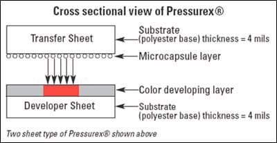
The sensor is composed of a layer of microcapsules pressed between a transfer sheet and a color-developing layer. The color-developing layer sits on the developer sheet or substrate made of polyester only four mils thick. The microcapsules rupture under pressure and liberate the dye. Just like litmus paper, the film color represents the incremental pressure related to psi or kg/cm² of the pressure applied.
How it Works
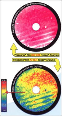 The special sensor film shows the pressure distribution and magnitude between any two contacting, mating, or impacting surfaces. For example, Pressurex® is a brand name for SPI’s pressure indicating film of thin Mylar, only 4 to 8 mils thick, that contains a layer of tiny microcapsules. Force applied to the film ruptures the microcapsules and produces an instantaneous, permanent, high-resolution topographical map of pressure variations across the contact area. The color intensity of the image directly relates to the amount of applied pressure. The colors are either manually compared to a color-correlation chart or electronically scanned and quantified with optical imaging techniques for more in-depth analysis. One such technique uses an advanced pressure analysis system called Topaq®, which extracts statistical data and high-resolution pseudo-color images. The advanced optical imaging analysis greatly improves the capability and value of the film. It defines the pressure distribution and magnitude in a variety of output formats. Vital statistics such as total force, average pressure, total area in square inches of contact, and standard deviation can be determined within +/-4% accuracy. Topaq® can also render histograms and population statistics on user-defined regions of interest.
Because the film is extremely thin, it can be applied to invasive, intolerant environments and curvaceous surfaces that are not accessible to common electronic pressure transducers. The sensor’s spatial resolution typically falls within a range of 5 to 15 microns. Visually, accuracy is specified at +/-10% and +/-2% using optical scanning and measurement systems. Tactile pressure-indicating sensor film comes in gauge sizes of 4, 8, and 20 mils, depending on the film type. Sensors made of the Mylar come in seven sensitivity ranges, which include pressures of 2 to 43,200 psi.
In addition to being highly economical to use, the films are disposable, quick, and simple one-timeuse devices, and they are unusually accurate for filmtype sensors. They are typically used in the aerospace, automotive, electronics, and medical industries. They are also applied to packaging, plastics, printing, and papermaking. For instance, the electronics industries use the sensors for measuring pressure during liquid-crystal display bonding, printed circuit-board manufacturing, laminating, and wafer bonding and polishing. The medical applications include clamping, gait analyses, ergonomics, orthotics, and prosthetics.
Real-time Measurements
The leaded-type of pressure sensor records and interprets the pressure distribution and magnitude between two contacting or mating surfaces and sends the data to a Windows-equipped computer tool kit. The Tactilus®, a matrix-based tactile surface sensor is essentially an electronic skin that is assembled to tight tolerances, individually calibrated, and serialized. The device is modular in architecture, which gives it portability, easy scalability, and simultaneous data collection capability from as many as four discrete sensor pads. Tactilus® employs algorithms that help separate the signals from noise and packaging that protects it from electrical noise, excessive temperature, and high humidity. The Windows-based sensor system consists of a piezoresistive or resistive sensing element, signal conditioning electronics, and software. Its application is simple and can be learned in only minutes.
The pressure sensors’ output typically ranges from 0.1 to 200 psi with accuracy of +/-10%, repeatability of +/-2%, hysteresis of +/-5%, and non-linearity of +/-1.5%. Applications include measuring the integrity of automobile door seals and other kinds of seals such as ultrasonic welds, lamination presses, heat sinks, nips, and wafer polishers.
Temperature-sensitive Cousin
A similar type of sensitive paper, called Thermex®, is available for indicating a relative temperature profile between the surfaces of seals. The paper turns a light blue color at the low end of a selected temperature range and further saturates at the high end. However, it does not change with temperature alone; it must be accompanied by a pressure change, so the device reveals both temperature and pressure variations in the seal. It is not necessary to break the sealing machine’s web, just tape the paper to the web that passes through it. The material being sealed insulates and cushions the Thermex® paper from the heat source just as the actual seal is insulated.
To check the back seam of vertical form and fill machines, feed a two or three-inch wide strip of Thermex® paper into the seam between the two layers of film while the machine is running. To check horizontal seams, tape a sheet of Thermex® paper to the forming web and center the paper between the edges of the web. If the Thermex® paper is wider than the “layflat portion (inches)” of the final package, the thickness of Thermex® paper at the ends of the seal will be lower. If this causes a problem, cut the Thermex® paper to lay flat along the width of the final package. The Thermex® paper should be taped all the way across the leading edge. If it jams going between the forming collar and the fill tube, cut the paper at an angle as is done when threading the machine. Position the paper down the web by using the “eye spot” on the design. If it does not have an eyespot, use an idler as a bench mark to measure where the paper should be placed to ensure it is in the horizontal seal area.
To check vacuum and flat web machines, tape the Thermex® paper to the formed web or one of the flat webs just before the top web or the second web is sealed. The goal is to secure the paper between the surfaces being sealed. The sheets can be overlapped if they are too small to cover the entire seal area. Secure the leading edges with small pieces of tape, and run the paper through the machine so that the second web seals to the Thermex® paper. If the Thermex paper is run through the knives, the knife alignment and the seals can be checked. The paper responds quite quickly, in 0.10 s or less, depending on the amount of heat and pressure. If it does not change color, then one of the following conditions can be the problem:
- The temperature of the paper is less than the minimum temperature of the Thermex® paper.
- The pressure is too low to transfer the heat from the heat source to the paper.
- Not enough time is allowed for the heat to soak through the materials being used.
A misaligned, nicked, or dirty die reduces the heat or pressure, and this area shows up as a white spot or a lighter colored area in the seal. If the material being used seals to the paper so that the color cannot be observed in the heat-seal area, fold the paper over on itself and it will break apart at the paper-to-paper interface.