


Articles: Panel World
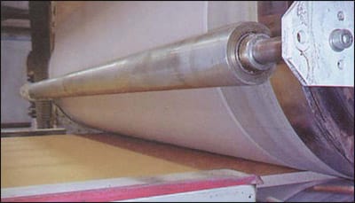
Particleboard with glue applied enters hot nip rolls with paper being applied to both sides of the board
Process engineer James Bowen of O’Sullivan Industries’ plant in South Boston, Va. noticed quality problems with (he company’s laminator machine. This particular machine is used at the facility to apply veneer paper to fiberboard and particleboard with the aid of nip rollers. The nip rollers on this piece of process equipment simultaneously apply heat and pressure to the paper and board.
Bowen explains. "We not only needed to know how much pressure we were applying to the paper and board but also needed to know if we were applying the same amount to each side of the five fool rolls."
Bowen noted that a lack of proper and correct contact pressure (in both heat and pressure) on the nip rollers leads "directly to de-lamination" of the veneer paper from the particleboard substrate.
Ultra low tactile pressure sensor film or "TPSF" (supplied by Sensor Products Inc. of East Hanover, NJ) was used in the process control determination procedure. Bowen used strips of the film to first test and calibrate the nip roller assemblies involved in the lamination processes: then tested the clamping force being exerted by the sealing bars. A mail flyer, he says, "is what led us to investigate the product." He was so impressed with the results obtained from the film that it now "will be a standard part of a new statistical process control (SPC) program being implemented" at the plant.
Tactile Pressure
In recent years, tactile pressure measurement has evolved from an art to a science. What once was a trial and error system with little or no accuracy employing carbon paper, clay bluing dyes and tinfoil has evolved; engineers and technicians can now determine force distribution and magnitude to an accuracy of ± 4%. Tactile pressure sensor film technology is non-destructive, relatively accurate, extremely efficient and easily calibrated. (The TPSF mentioned here is specifically known as Pressurex® and is a registered trademark of Sensor Products.) Generally speaking, any situation where two components either contact or impact in a normal (perpendicular) fashion is a viable candidate for utilization of the TPSF technique.
TPSF can be used in both laboratory environments simulating manufacturing conditions and also during the live process itself. TPSF is a single use system, capturing maximal pressure loading at a static moment in time. The film is also quantifiable, yielding fairly precise values of force magnitude of any point across the contact surface area. TPSF could be considered an extension of finite element analysis (FEA) with one substantive distinction: The film is a post-process interpretive tool that actually collects stress and force data.
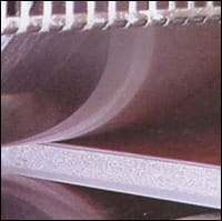
Same board as opposite page comes out of the nip rollers.
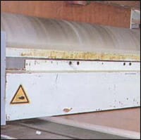
Finished product leaves nip rollers.
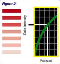
Microcapsules embedded in the film rupture at precise pressure levels, producing a visible color change and a high resolution image of pressure distribution and magnitude. This quantifiable color change is directly proportional to the amount of pressure ap¬plied (Figure 1). The user is able lo visually inspect the film for significant variations aberration and general uniformity. Spatial resolution of the TPSF system is .005 mm to .015 mm. yielding ultra-high definition imagery of force profile (Figure 2).
Interpretation
After application of compressive load, TPSF can now be analyzed in several different ways. The quickest and most economic technique is by visual comparison to a color calibration chart (conceptually similar to using Litmus paper). The engineer can match the film’s resultant color to this calibration table for an approximate indication of pressure magnitude. Voids, pits, micro-cracks, warping and surface aberrations are immediately apparent upon visual inspection. Typically the visual interpretation method yields accuracy of ±15% full-scale (kg/cm:). Additionally, when analyzed with an optical image analysis system, TPSF can threshold an image to determine precisely how much contact area resides above and below certain parameters. (The optical image analysis system mentioned here is known as Topaq and is a registered trademark of Sensor Products Inc.).
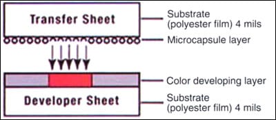
Figure 1. Illustration of a cross-section view of a piece of tactile pressure sensor film
The system consists of Windows based software and a specially calibrated scantier to read and interpret the film. Images rendered by the image analysis are accurate to ±2 – 47e full-scale, and are accompanied by a wealth of statistical data. Key features of the analysis system include the ability to produce histogram data of the image being analyzed. The system provides not only for analyzing the entire interfacial surface, but also for the study of small and problematic areas (which can be enlarged, enhanced and carefully scrutinized).
As a measurement tool. TPSF generally results in a quite positive return on investment. A technician can be trained in the technique in a matter of hours. The TPSF and the optical analysis system have become powerful tools in the arsenals of manufacturers’ production and R&D facilities, bringing manufacturers and users closer to full-process standardization. Using TPSF in conjunction with the image analysis system lends a high degree of statistical validation to any interfacial analysis.
O’Sullivan Industries’ success with having both the nip roller assemblies and the seal bar clamps in its lamination presses efficiently and quickly calibrated shows how such a metrology tool can lead to greater production control but also in its being included in an SPC process initiative.
Panel manufacturers who must deal with combined pressures of compressive force (lamination) and nip roller force (extrusion and parallelism) as routine components of their production process now are able to address both concerns efficiently and inexpensively. O’Sullivan Industries’ success in addressing both concerns now means a more uniform and predictable final product.